Archive
Train derailment at Stoke Lane on the 27th Aug 2013
This is a very short blog, as I don’t have time to go into detail. Yesterday I had a really interesting presentation on the factors behind the train derailment at Stoke Lane on the 27th Aug 2013.
Incident Overview
Nottingham train station was closed for a 6 week period, in this period company X tried to take this opportunity to lay some cables below the track (that was not operating as station was closed). In order to lay the cables they used some pipe jacking to lay a 1.2 m dia tunnel under the track. This required two shafts to be sunk, allowing the miniature TBM to be lowered into the shaft and jack the pipes in behind it.
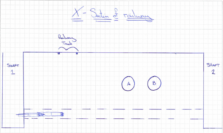
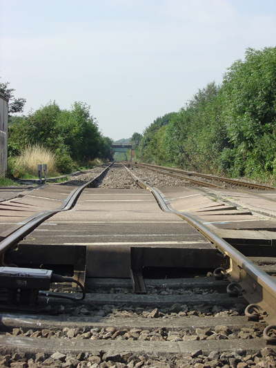
Several weeks later a train consisted of a class 66 locomotive and 30 bogied, tank wagons, loaded with diesel fuel. It was travelling on the up line towards Nottingham at a speed of around 53 mph (85 km/h) when the driver noted an irregularity in the track as he went over the crossing. Shortly afterwards, the trailing wheelsets of the 26th and 28th wagons derailed and ran for approximately 850 metres before the train’s brakes brought it to a stop, as air leaked from a punctured air reservoir tank. None of the other wheelsets were derailed. Both derailed wagons remained upright and there was no leakage of the diesel fuel but the track and some wagons suffered damage
Our involvement
As part of the Rail Accident Investigation Branch (RAIB), Donaldson Associates were asked to look into the method statement and design of a 1.2m diameter tunnel located directly below the area effected.
Findings
The findings are due to be released to the RAIB next month or so, however the preliminary findings are quite shocking. It appears that there was a number of factors that caused the derailment. I will try to explain just a few.
1) Most surprisingly, it seems that no one recorded the amount of spoil that came out the tunnel. It is now understood that twice as much spoil was removed compared to the volume of the tunnel. Where was this soil coming from? How did the contractors not understand that this was a serious concern?
2) The designers were not aware of the main line sewer pipes running above the tunnel until much later, after the tunnel design was completed. These sewer lines were carrying 4m3/sec of sewer, hence some substantial loading.
3) The depth of the tunnel was designed by calculating the live load on the rail way line, ensuring the crush capacity of the tunnel exceeded the live loading. It never factored in the weight of the soil between the railway and the tunnel.
4) The annulus (the space between the void created by the TBM and the concrete sections of the tunnel) of 25mm was not filled with grout or Bentonite. This would greatly increase the volume loss.
6) The volume loss in the design calcs was estimated at 1%, however empirical evidence shows it should have been around 2-2.5%.
7) The K value, that calculates the trough of settlement (Clay would be lower, gravel higher), used was 0.6, however for gravels it should have been around 1.2. This would have given a far deeper settlement in a more localised area.
8) Network rail (NR) do not allow works to proceed if the settlement is above 5%. If the volume loss and K values had been more realistic the settlement would have been around 7mm. Although this is nowhere near the 20mm settlement they experienced it would have been enough to stop the works in the first place.
9) Although the NR stipulate that there is to be no settlement in excess of 7mm, they do not stipulate any trigger levels. Additionally the company that monitors the tracks, recorded 20mm settlement, but didn’t do anything about it. There was no process in place to deal with the consequences.
10) The monitoring of the line only monitors the track. The soil below is not monitored. On inspection the track was spanning 700mm voids wit a span of 2m. No one was even aware of it.
As you can imagine the repercussions of this will be vast. The asset managers within NR are sure to have a busy time over the next few months. As a side point, the asset manager that signed off the works wasn’t even a ICE member let alone a CEng. Infact he had some random degree, yet was signing off works left right and centre. Sounds like he should join the RE (it sounds very familiar to my early days in the RE).
Dodgy looking columns.
Having completed and submitted the tender for the North Eveleigh 11kV relocation project the other week I moved on to two other projects which are both part of the Rail Panel work. This panel consists of three consultants for which SMEC are one that get the honour of submitting proposals for various maintenance and upgrade works for Sydney Trains. Although some jobs are rather chip shop there are plenty of gems on offer and as the panel is a three year agreement it has provided a steady revenue for the rail structures team which I think was greatly appreciated last year.
The first is another tender of what Sydney trains call a Request For Proposal (RFP) for some building modification works on a substation about 50km north of Sydney. I attended the site inspection and even to me semi-trained eyes it looked like a fairly straight forward job. The intention is to remove certain outdated equipment and provide an admin room in its place as well as a seperate extension on the opposite side of the building to house a new DC switch room. I have engaged an architect, surveyor, building services consultant, building code compliance consultant and the pertinent in house specialists and will work on the proposal next week for submission on Fri. Thankfully there is no electrical work to be carried out like the last tender so I hope to control costs a little bit more to get a competitive price together. I’ll update more on this next week I am sure.
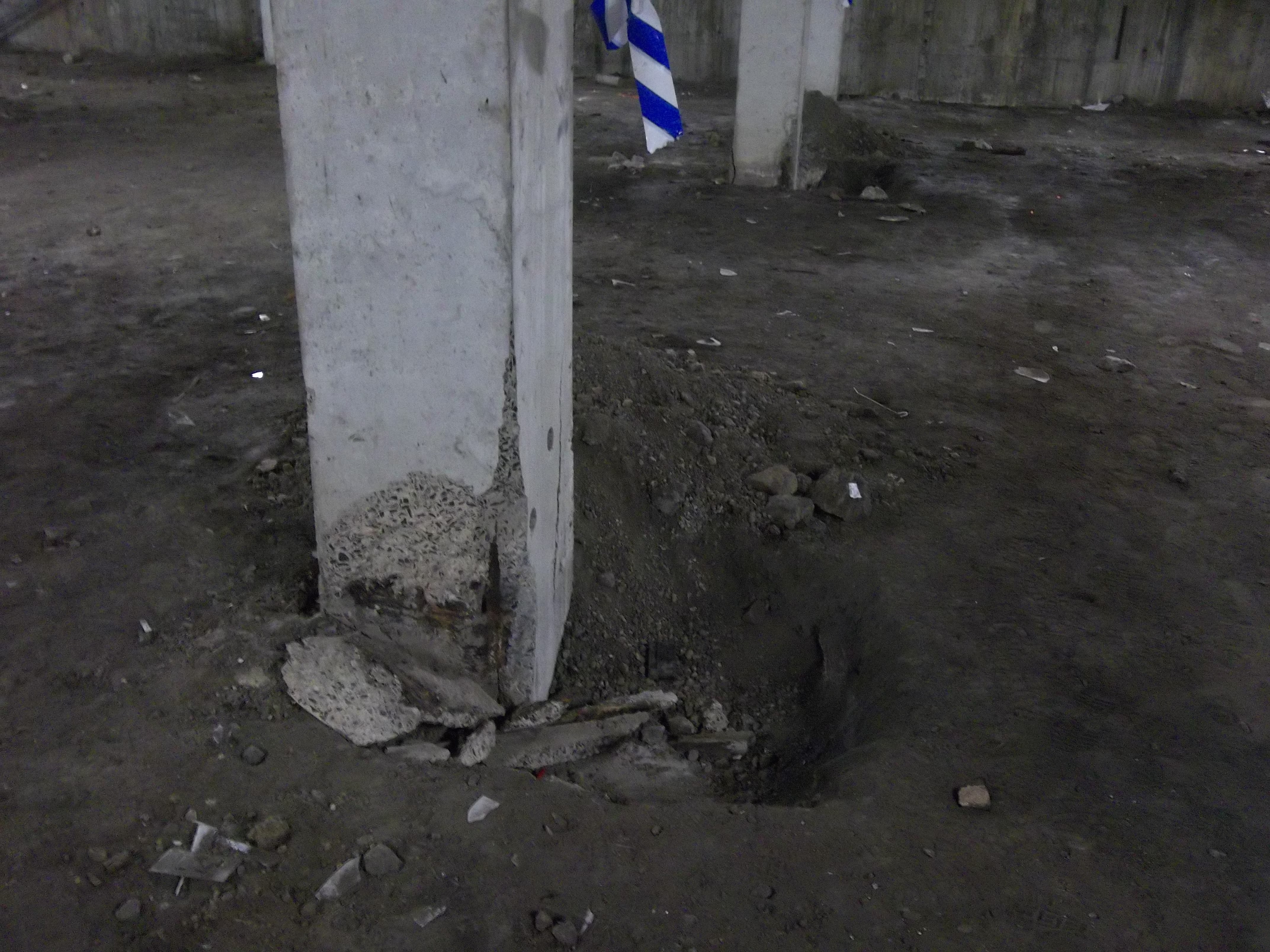
The second project moved my focus back to Eveleigh but on the other side of the tracks where a maintenance centre is located. Another consultant from the panel had originally been engaged to conduct an investigation of the basement columns where corrosion and subsequent concrete spalling had been observed. The initial concern was whether there were any structural capacity issues. We were asked to comment on the report findings and state whether we agreed with them. The original report concluded that up to a 50% loss of reinforcement section would be acceptable and that the current imposed loadings were not likely to be near the design loadings. The actual level of corrosion has not been detremined and although I haven’t visited the site the photos I have indicate that it is quite bad in places.
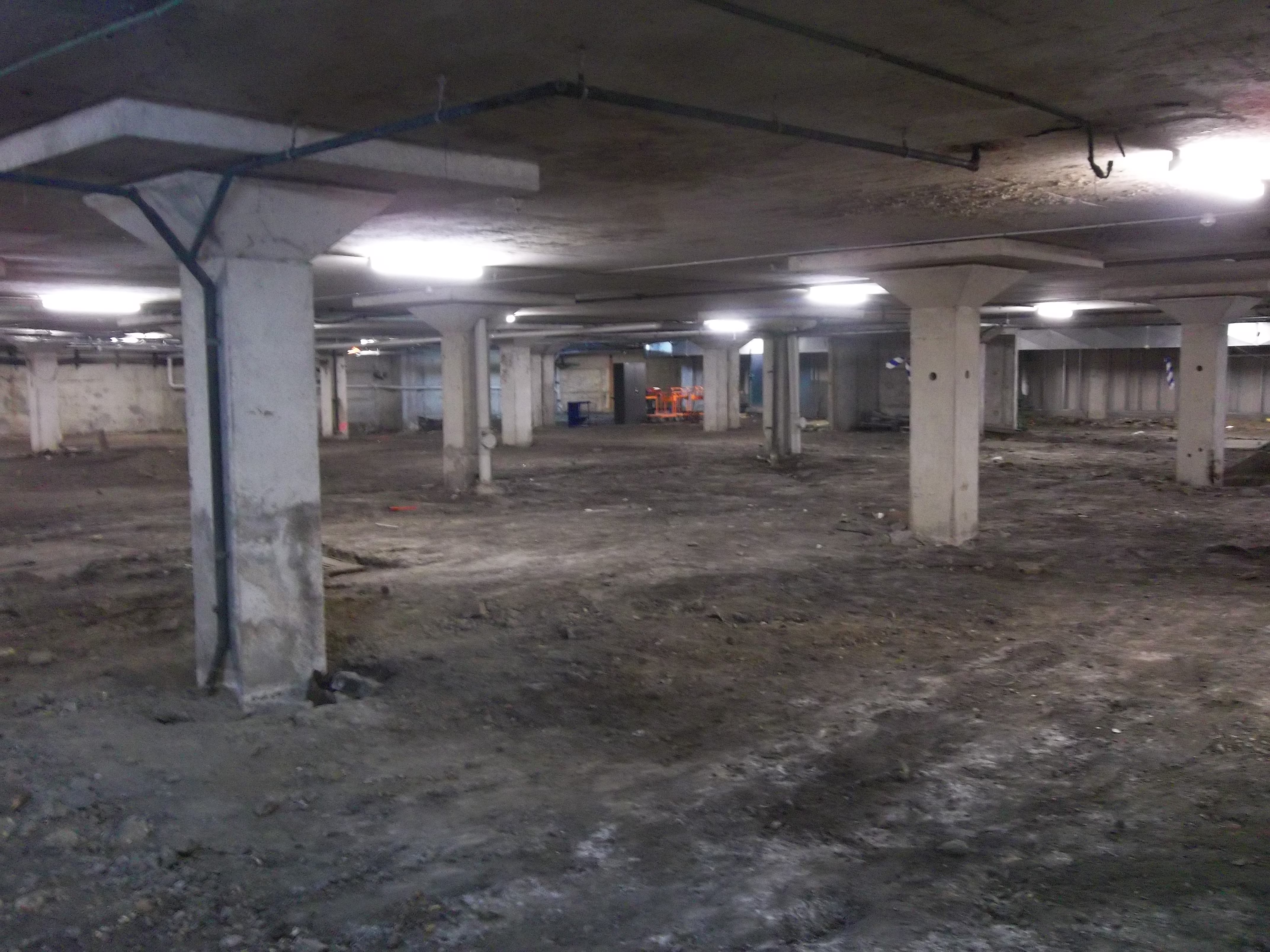
Initial thoughts were that stray current may be the cause of the corrosion. The tracks run parallel to the depot and it was proposed that the piles were picking up stray current from the tracks and conducting it to a point closer to the substation. However, the corrosion has only been observed above ground level and when the ground to the top of the pile cap was investigated there were no signs of corrosion. It must be pointed out as can been seen from the photos that the area of concern is approximately half the footprint of the building and there is no ground slab, the other half of the basement is in good condition (has a floor) and is used as an underground car park.
![train1[1]](https://pewpetblog.com/wp-content/uploads/2014/01/train11.gif)
Apparently, the rate of corrosion from stray current is 9kg/Amp/Year. When iron corrodes by stray current, or by other means, the iron ions have to combine with anions which is commonly oxygen, therefore the corrosion product of iron is generally iron oxides or rust which are insoluable. However, the rate of diffusion of oxygen into concrete can be slow and insufficient to combine with the quantity of iron ions being produced. This means the iron will combine with other anions such as sulphates, chlorides etc which are soluable and so no visible corrosion product exists except a ‘shiny’ surface. The disadvantage of this is that severe corrosion and loss of reinforcement section and structural capacity can occur before corrosion has been identified. The exposed reinforcement shown in the pictures is all covered in rust and so it was assumed (by a specialist stray current consultant) that stray current was not a major factor in the reinforcemnet corrosion but it could have occured after. As a result I compiled a report (more of a memo really) that proposed firstly a Cathodic Protection system to treat the possible cause of the corrosion and a physical column repair method involving ‘jacketing’ the columns in a 150mm RC layer. A few days later the client responded saying that they do not consider the stray current as an issue (the basement is poorly ventilated and conditions are very humid), therefore they did not want to pursue the CP option (which in their eyes came with an unsustainable electric bill) but they asked for a refernce design for the jacketing option. At present I am working up the details for this option which will assume the existing reinforcement in the columns is not contributing and so additional reinforcement will be placed on the outside. This is likely to increase the current 457mm square dimension of a 2.6m long column to 757mm square which is one short, stocky column.
Going back to the initial structural capcity check, I did not agree with the previous consultants conclusion that 50% loss of reinforcements section could be accepted (I calculated, well mainly an excel SS calculated) that only a 25% loss would be acceptable. I thought this would be a bold call considering a technical director did the initial calcs it appears is was due to the assumed compressive strength of the concrete. They had assumed 25MPa but I had the benefit of using actual core samples that were tested at various locations which using the code (no. of samples, sdev and all that) I used a value of 19MPa. My issues with all this so far is that firstly the actaul state of corrosion or loss of reinforcement section has not been determined and it looks like it will not either so there is a lot of assumptions. The second is the cause, it appears that the basement conditions may be the primary casue but to my mind stray current has not been ruled out and could still be the cause because no intrusive testing has been carried out. The big fat caveat with my design proposal at the moment is that this could be a ‘band aid’ job and unless stray current is conclusively ruled out by measuring the presence of a current flow through the columns and the basement conditions are addressed then at some point in the future the reinforcement will corrode to the point concrete spalling again. In fact any new reinforcement introduced to the columns without addressing stray current will be anodic to the existing reinforcement and thus increase the rate of corrosion in the new reinforcement. I will update again next week on how it all goes.
The Impact of the Arctic Vortex in a Design Office
Since the end of the holidays the weather has been a touch on the chilly side. In early January there was even a frostbite warning for people venturing on to the streets and the public transport literally froze. So since the New Year there have been 5 snow days, a bank holiday and then my mentor took 3 days sick leave. Combine this with a week long delay to get the energy modeling software and the knock on effect is a delay in productivity. Not always a bad thing except I was hoping to write my TMR using my project as a basis. Now that is in, the tempo is picking up, naturally. The modeling is nearly complete and I am now working on equipment selection and looking at incorporating energy saving technology in to the design. The first is to use a variable refrigerant flow system as the primary heating system. This is an old Asian 50’s technology which is starting to become very popular over here because of its efficiency. The principle is instead of pumping heated air round a building in large inefficient ducts, you simply pump the refrigerant directly to the room it is needed in where a fan coil unit then blows over the expansion vessel producing cold air at the right condition. What is even more impressive is that the expansion vessel can be switched from cooling to heating with an automatic valve change. Even cleverer still as that all the fan coil units (up to 50 odd) can be linked and can become heat recovery units too so if a room is too cold, the refrigerant in a room that is too hot can be directed to the cold room without going through the compressor. The Compressor/condensor unit is kept out side, so no mechanical room needed, and is about the size of a large fridge. As the building is aiming to get big points for green technology this is looking like a good system. The second design is for a Solarwall heating system. Placed on the SE/SW wall of the building this is free heating for relatively little investment ($20,000 for 2000 square feet) provides nearly free heating. A semi permeable polycarbonate shell heats the air, through solar energy, against the black wall which rises up the wall and is accumulated at the top where it is then pumped in to the space through a fabric duct with holes, like an ITC aircon duct. This will be great in the large warehouse area which VRF struggles to heat and often has the large loading door open. I have not worked out the energy produced but this was used in Harrisburg heat my warehouse too (see Matt Fry’s blog) where it has proved very effective.
I took the opportunity to visit my possible next project, Hale Hall. This former 1920’s barrack block was retro fitted with HVAC over the years before catching fire in 2006. Going round the building meant getting dressed in protective suits because of the presence of mould and bird poo. What was strange was that the fire damage was limited to the roof of one side but the whole building was water damaged and trashed. It was like walking through a time tunnel because the place simply had all the top secret stuff ripped out and was left. Not even desks had been cleared. Below are some of the odd HVAC designs I discovered.

Duct work that missed the obvious window opening
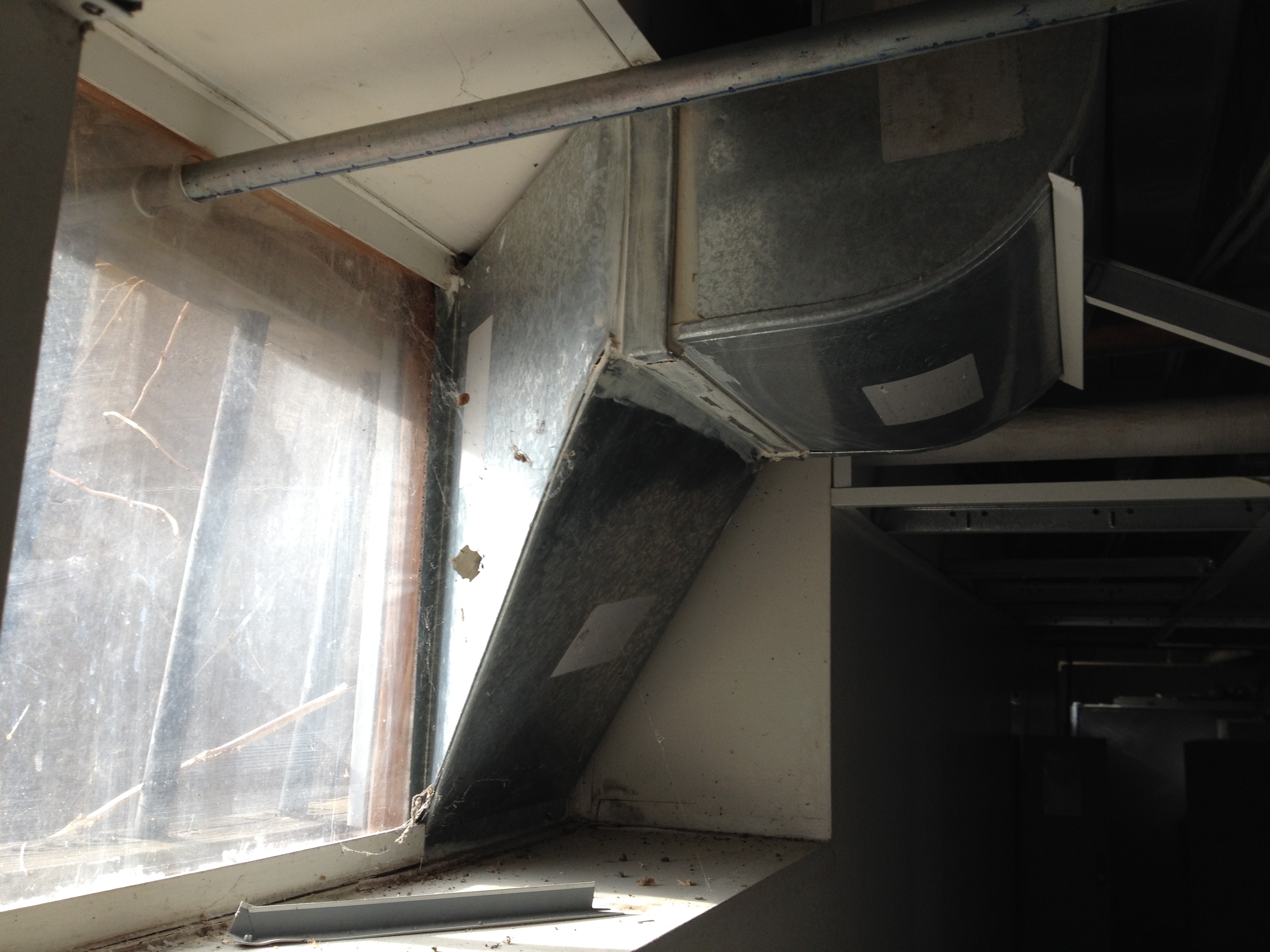
Another duct that fails to go through a window effectively
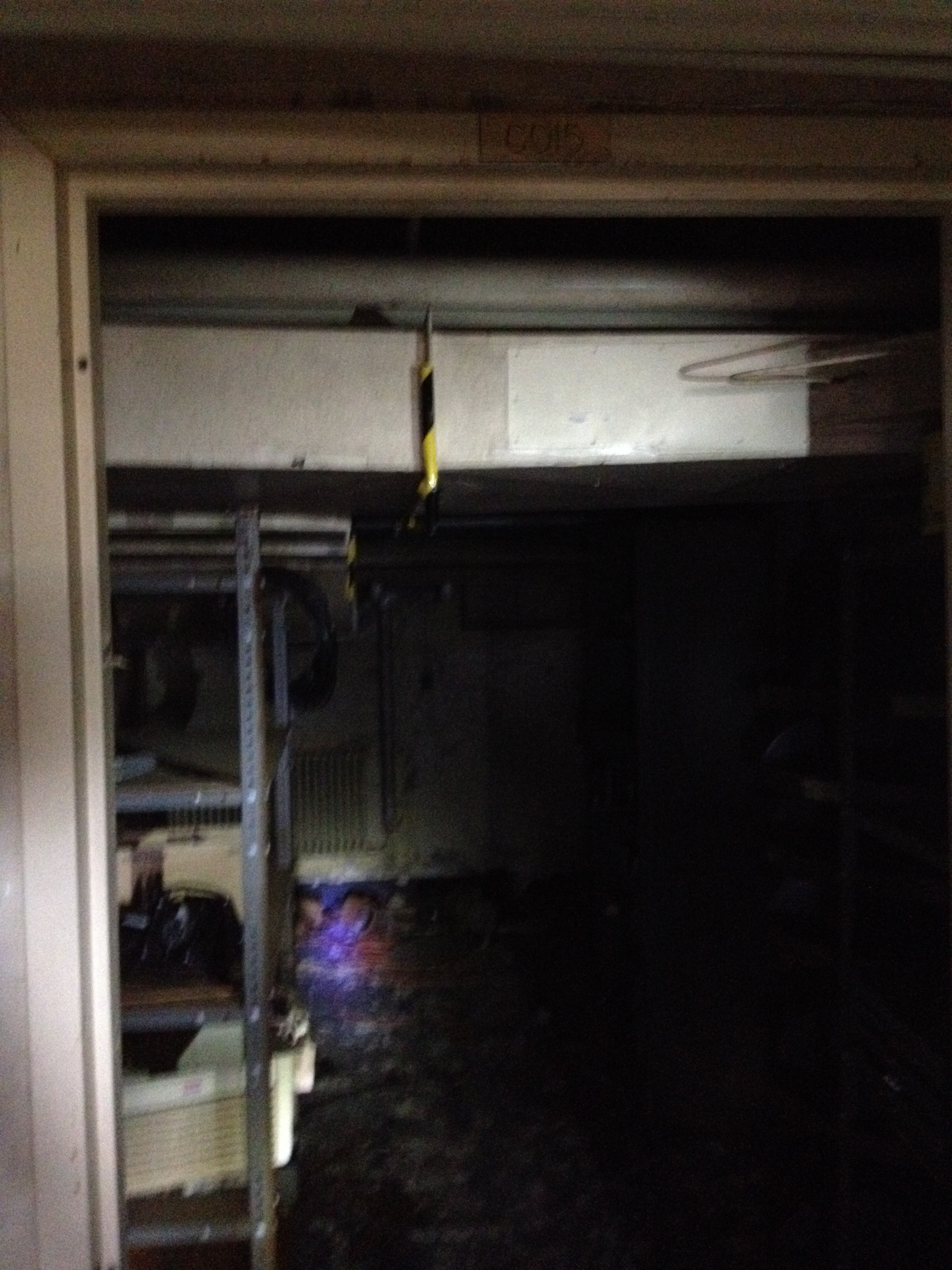
Duct work on other side of a door. Note the warning tape on the sharp joint
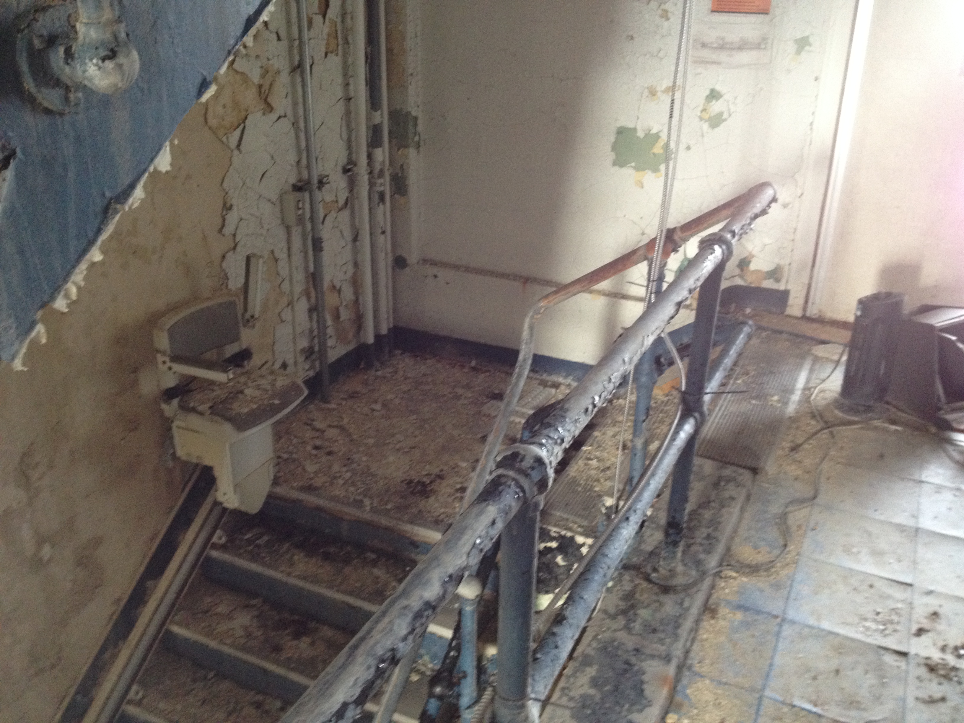
Stair lift – how do you get up the last 3 steps?
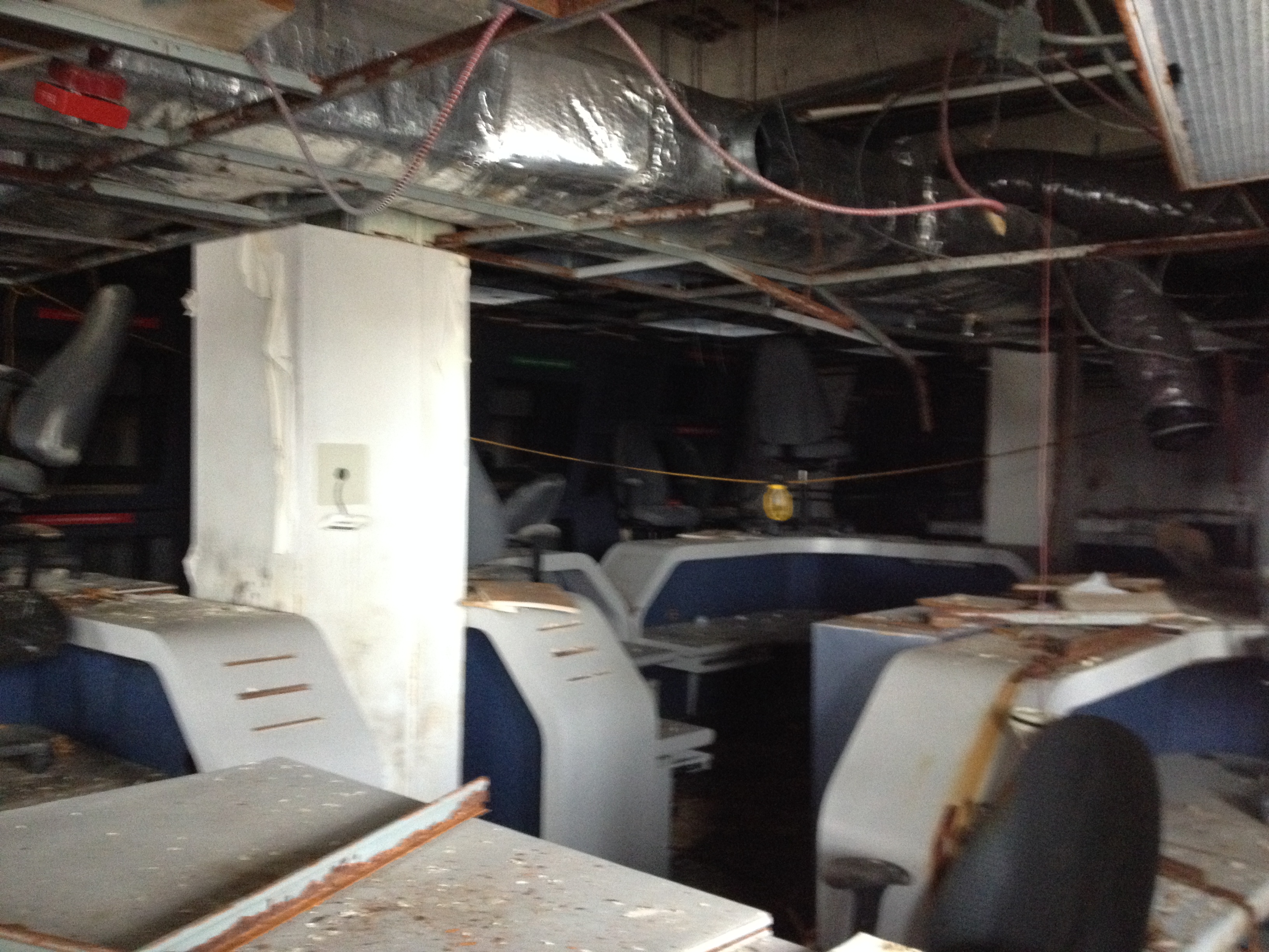
The Starship Enterprise Office that used to be Top Secret
As you can see all the HVAC will come out and be replaced! There are a few more weird designs but alas my camera lasted 11 shots at -8. The current budget is for $20 million to do the revamp complete. However the current estimate is $18 million to carry out the demolition alone which includes clearing out the debris and old office equipment. If this had been done at the time in 2006 instead that would have saved a packet. Now a specialist contractor is needed in full 4 Romeo to clear the building because of the biological (and asbestos) hazard. This project is likely to get paused whilst the budget is reviewed.
Two smaller projects are coming my way potentially. One is a new hangar at Ft Drum in up state New York. Based on a current design it will be my first chance on my own to design the HVAC. The second is a small Visitor Control Centre office block of about 5000 square feet which also requires HVAC. I have also been asked to go to West Point next week to look at a barrack block HVAC design. It is to have a new heating/cooling system which consists of underfloor heating in the winter which is then switched to a chilled roof arrangement in the summer. The Department for Public Works is the customer but is concerned that the set up will lead to condensation and mould growth even though it is ventilated. I will be going with the section chief as a technical expert. Best do some reading up!
And in other news…..
The cold weather is set to continue and the deep south is now in chaos after 3 inches of snow fell because they don’t ever get snow and had no ploughs! The Superbowl is this weekend but no Ravens this time as they actually got dropped from the wild card slot after a terrible end to the season. And the gun debate continues after a shooting in a Mall 30 minutes away. Luckily I have a thesis to distract me.
It’s Getting Hot In Here…
Things have really gone up a gear in the last month and as the Minox B Blower installation date draws closer I feel more and more like the BP SPA and less like the Royal Engineer on Secondment. This can only be a good thing given the circumstances.
Minox B Blower
The Minox materials left the beach on Monday, over a week after the planned departure date due to this wonderful weather restricting shipping in the North Sea. The materials were due to arrive on the Clair today, however the weather again has me at its mercy. I have high hopes that the material will be unloaded on Friday, but it really is in the lap on the gods on that front. My first vendor mobilises early next week and while they don’t require any of the materials, 6 Feb is my redline after which things are going to start to get interesting.
The project has skirted closely around failure over the last 2 months, with the closest being the HVAC vendor feeding back on their own (2 year old) designs, 6 weeks before offshore execute, that they were not fit for purpose. The crux of the matter was that in a previous incarnation of this project, the vendor had planned to upgrade the condenser, evaporator and compressor on an HVAC system (6kW to 12kW), without upgrading the coolant lines. A suitably chastised vendor went away over Christmas and came back with an up-reved workpack for the 4th of January concluding that a two day extension to their mobilization would allow them to upgrade all of the existing lines (about 50 m worth). It doesn’t sound much here, but it was a minefield of stakeholder management at the time. In the end, the asset had no issue with swallowing the extra days and the requirement for hotworks to braze the lines. The original plan to use a weldless connection technique was deemed not ideal given the number of connections that would have to be made with the new scope.
Following that was the news that one of the nitrogen lines on the current blower had sprung a leak leaving the area out of bounds to all personnel. Again, I spent time understanding the scope of the issue and discussing it with the appropriate stakeholders and due to the leak being more of a seep, the restrictions within the area have been lifted from my team. Part of this is due to the fact that the installation of the Minox B Blower addresses one of the platforms key vulnerabilities. At present the A blower is on 100% duty with no standby to deoxygenate seawater for injection into the reservoir. Without it production falls off a cliff. With this in mind, the asset is willing to take a little risk on getting the B Blower installed, and anyway, whats a little nitrogen going to do…
So thats Minox in a nutshell.
HP Cooler
Following on from the fun and games I had last year with the Clair Coolers replacement, I am the SPA for replacing the HP cooler. This scope is in Define and I have been responsible for putting together the £1.5m of funding to get it installed. One of the key issues that I have been driving is that of defining the project drivers. The original coolers were replaced due to a vulnerability in the process used to weld the tubes into the tubesheets, essentially the fabricator had skipped a step and failed to add galvanic protection to the shell side of the tube sheet.
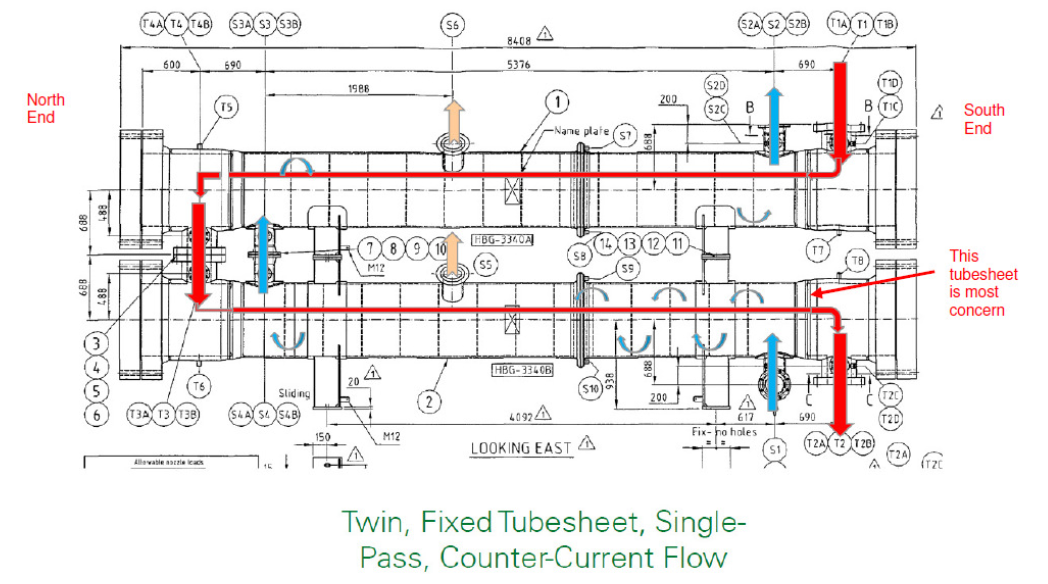
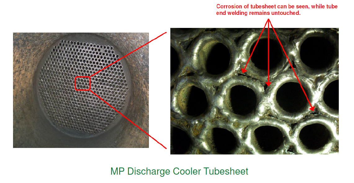
Given that the shell sees thousands of litres of hot sea water a day, and the designs allowed for an area of relatively undisturbed flow around the junction between some of the tubes and the tubesheet allowing carbonic acid to form, it was only ever a matter of time before corrosion ate through the HP/LP interface. This issue is a key driver for the installation of the HP cooler as the same fabricator and QA procedures were responsible for its commissioning. However the situation at the HP cooler is subtly different with the shell geometry being different, with far less undisturbed coolant flow and the tube side flow being effectively dry, so little or no risk of H2S drop out and corrosion on the tube side. While the failure of the HP cooler is fairly certain, the difficult question is what the time frame is. If it is less than 5 years, then there is a huge driver for this project to be complete in time for the 2015 Turn Around, a planned shut down of the asset. I am keeping a close handle on this issue, but there are a couple of other stakeholders who I am working closely with to ensure that this issue is brought home sooner rather than later.
The other issue that I am dealing with on this scope is the question of tube rupture. There exists a deficiency in the design of relief systems for HP/LP interfaces across the North Sea, mainly due to the lack of understanding of this issue when most of these systems were designed. I am quite lucky to be right at the forefront of this research with this project, playing a direct part in how the issue gets resolved for the HP cooler scope. A shell and tube heat exchanger typically has a hot medium under high pressure running tube side and colder lower pressure medium running shell side. Should catastrophic failure of a tube occur, computer modelling shows a transient pressure spike based on the interaction between the high and low pressure mediums that reverberates around the shell effectively magnifying the initial effect. This pressure wave then propogates away through whatever route it can find. Because this near instantaneous interaction between the two medium has never been fully understood until now, the relief mechanisms built into these systems are underspecce’d. In the case of the HP cooler, the BP discipline engineer I have been working with has had to take his analysis right to the limit of the ASME codes and the relief line still falls below unity at the elbows.
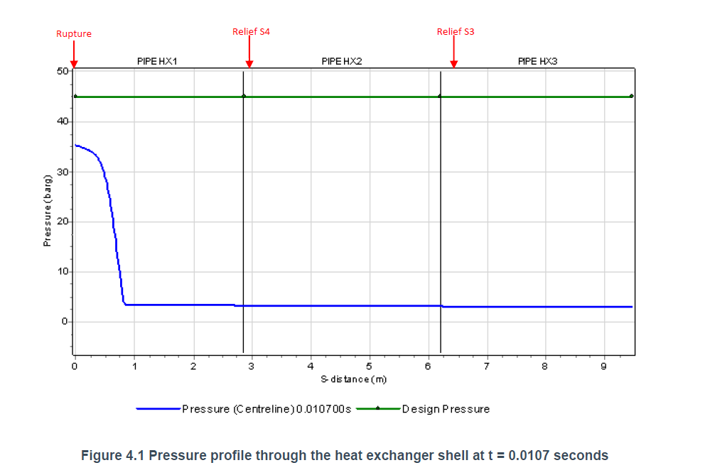
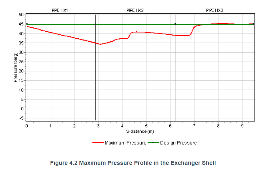
Effectively, if one of these events occurs, the pressure wave would take pretty much every part of the system, for a radius of several meters, up to the limit of its test pressure, with the exception of the relief elbows which would be taken just beyond. This potentially gives me a specification for the redesign of these elbows within the HP cooler scope, but it is a huge judgement call on the part of BP with the only real mitigation being that the chances of it happening are very remote. Sadly most of this information has come to a head in the last week or so, a missed TMR for sure unless Bren or Nick want to give it a bash.
Flowline Bracing
This job just seems insignificant in comparison to the other two, but I am really keen to get it sorted before I leave BP. It is scheduled for a May execute, although the project itself has been in offshore execute for almost 2 years now. I now have a WGPSN engineer assigned to it and so things are moving in the right direction. The thing I am most chuffed about is picking up on a potential flaw in the design. To put the new steel bracing in the project is replacing some temperature transmitter assemblies, the originals have an effective length of 100mm and the new ones 200mm and they support a 1kg transmitter at the end. Basically a 0.5″ threaded tube cantilevered out from a thermowell on the horizontal axis with a 1kg lump at the free end.
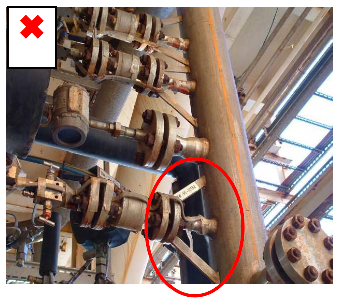
The feature directly above the red circle is the situation I have, a metal can on the end of a strut, although in my case the strut is being modified to be double this length.
I put in a query to the instrumentation engineer who specified the new assembly as to what guarantee there was that the new assembly would with stand the doubling of the moment around the thermowell and any vibrational effects from the line to which it is to be attached. The response was not a great one, I have my fingers crossed that this is not a show stopper and while I have a feeling that the assembly is probably good for the increase in moment, I am not so sure about the vibrational effects. I will be disappointed if this project gets kicked into the long grass again.

This is the kind of solution I am expecting, of course rotated though 90 degrees.
In other news
There is more, but I think I will have to save it for the next post as it is late and you are probably bored (well done for getting this far though).
Corine is quite big now (possibly a surprise to you, but number 2 is due in 8 weeks, a girl), but is soldiering on regardless. I have some hard deadlines to hit for my thesis so that it is mostly in the bag by the time she arrives. Mostly for this reason, all extra curricular activities are on hold.
I am concious that I have not included any pictures in this post, mostly because I am writing on my PC and not the work laptop where I keep all of the ‘cool’ stuff. So as a reward for getting this far, here is some more Dilbert for you. He really does keep me going some days…

I don’t just complain about civilians…
I do some work too….
Actually writing down stuff that sounds a bit clever seems to be de rigueur at the moment so I thought I better make a bit of an effort, I can’t be flippant forever and RF is right CPR is somewhere on the horizon. The bridge foundation I’ve been working in in the final stages but it’s not been on my desk for a week or so. Much of last week was spent preparing a basement impact assessment for a domestic property in Camden, quite interesting (in an engineering sense) and not too many numbers thankfully, that’s now with one of the environmental guys to do the flood risk assessment and awaiting RFIs to be returned from the developer. Something that’s been hanging around in the background for a while has been a gone wrong wind farm, thankfully not gone wrong because of us but Ramboll have been called in to provide expert witness services, I think we could be prosecuted under the trade description act as I’m the only one from geotechnics working on it currently and I can’t claim to be an ‘expert’. The initial request was to do with the actual foundations of the turbines themselves there were doubts raised during the checking process (which was complete after construction commenced) this didn’t progress very quickly initially although it has since landed back on my desk, thankfully with the help of Repute an uber pile calculation programme and the structures modelling software I’ve not had to wrestle with ‘piling in weak rock’ as the piles go down through peat and glacial tills to Sherwood Sandstone underneath. The second part of the contract was to conduct a check on the crane foundations that were constructed for the build phase. In short the foundations were subject to a litany of design problems and the tender submission was woefully inadequate although the tender drawing alluded to this the design and build contractor never really developed the solution and the ‘typical solution’ became the ‘for construction’ solution and the contractor progressed without the stipulated written consent from the turbine manufacturer. That’s the short version, getting this far along has required an awful lot of reading and cross referencing of documents and has felt a little like doing another TMR. Below is the whole report that I have prepared so far on the initial design and will start on the remedial works tomorrow. I won’t blame you if you don’t read it.
1. Introduction
1.1. Background
Ramboll have been engaged as an expert witness commissioned by Hill Dickinson on behalf of BSW Consulting to carry prepare a preliminary report in relation to the design of the crane platforms used to erect the wind turbines at Orchard End Wind Farm.
1.2. Qualification of Authors
The qualifications of the authors of this report are summarised below:
Rich Phillips, Graduate Engineer, BEng
2. description of project
2.1. Location
The site is located at North Wood’s Hill Farm in Wyre Borough, Lancashire. The area is arable land which is drained by a number of ditches discharging into the surface water channel known as the Momen Gutter.
2.2. Wind Farm Development
To date 2 wind turbines and associated support infrastructure, control buildings and access routes have been constructed. The client for the development was REG Windpower Orchard End Ltd, part of the REG Windpower Ltd group with Askam Construction Ltd appointed as the design and build contractor. The initial tender designs for the scheme were provide by BSW Consulting Exeter Ltd, BSW were later appointed by Askam although never formally novated.
2.3. Issue
BSW’s design responsibilities included the working platforms used by the turbine provider, Vestas, to operate the cranes used to erect the turbines. In support of the design of the scheme they were provided the Ground Investigation Report (GIR) supplied by Ground Investigation (Wales) Ltd who had been engaged by REG to provide the necessary geotechnical information for the design of the scheme.
In Dec 12 it became clear that remedial works were required on the crane pads, BSW provided a design and remediation began in Mar 13. During the erection of Turbine 1 the crane outrigger suffered excessive deflection and the work was aborted. As a result of this a piled solution was pursued at the request of Askam.
3. References
The following sources of information have been used in this assessment:
- Email Sarah Naylor/Paul Jackson, dated 24 Dec 13, Ref SJN.940401.6129.
- Geo-Environmental Site Assessment Report, dated Jun 11, Ground Investigation (Wales) Ltd.
- BSW’s privileged report (we have been instructed to treat this as sensitive).
- Application Suggestion for Orchard End Wind Farm from Tensar International Ltd supplied to BSW, dated 7 Dec 2011.
- Working Platforms for Tracked Plant, BR 470, 2004, Building Research Establishment.
- BSW design drawings (Tender):
- Site Construction Access Track Layout, Sheets 3 & 4, dated Dec 11.
- Road, Crane Pad and Hardstand Specifications for Vestas Turbines V80-V90-1.8/2.0MW V82-1.65MW and V90-3.0MW, dated 9 Mar 10, Ref 0002-0277 V03
4. pre-design information
4.1. Ground Investigation
The GI conducted 2 No boreholes located in the centre of the turbine foundations with a larger number of machine excavated trial pits completed under the foundations and along the proposed access track alignment. Soil strength parameters were determined through the use of:
- SPT.
- Shear vane tests.
- In-situ CBR correlation tests.
- Laboratory testing including tri-axial, oedometer, particular grading and Atterberg tests.
The outline sequence of strata and design parameters found in the borehole under Turbine 1 are detailed in Table 4.1.
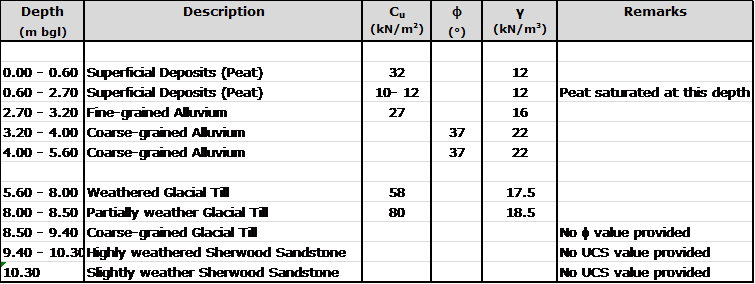
Table 4.1. Sequence of strata encountered in Borehole 1.
4.2. Qualitative Assessment
Section 6 of the GIR provides assessments and recommendations for each element of the scheme and in particular highlights the geotechnical hazards on site; the first hazard detailed in the report is the presence of the low strength deposits of peat and alluvium. The key assessments and recommendations relevant to the Turbine 1 crane pad made in Section 6 are as follows:
- Water was encountered in the low lying areas during excavation between 0.6m and 0.9m below ground level. (Ref 6.4.5)
- ‘Hand vane tests conducted within the upper Peat horizon indicted an undrained cohesion of typically 30 kN/m2, reducing to around 10 – 20 kN/m2 within the saturated zone below around 0.6m depth. Values of undrained cohesion reduced further within (sic) increasing depth, to values as low as 6 – 8 kN/m2. The values….indicate that strata of very low-strength and high compressibility occur beneath the loaded zone of the crane pads.’
- CBR correlations across the site frequently returned values below 1%.
- The crane pads must not be found on the Peat, instead the full thickness must be excavated in order to reach the material below.
- The recommended figure for acceptable bearing pressure on the Fine-grained Alluvium was 35 kN/m2 if this loading could not be achieved then excavation to the Coarse-grained Alluvium should take place with a maximum applied pressure of 50 kN/m2.
4.3. Summary
The assessed soil design parameters combined with the qualitative assessment of GI (Wales) indicate the presence of a slightly stronger ‘crust’ in the top layer of the Peat above the saturated zone. The material below the crust is significantly weaker and unpredictable, a foundation design might be suitable for the upper layer but the pressures applied to the strata below might exceed the allowable bearing capacity.
5. Design approach
5.1. Design Loading
BSW based their initial calculations for the design loading on a public document published by Vestas (the turbine manufacturer). This document explicitly states:
‘This document is not sufficient in and of itself to construct…Crane Pads…and must be supplemented for each project and site before construction work commences….
The exact design of … Crane Pads… must be agreed with Vestas in writing prior to start of construction.’
This document stipulates the minimum bearing capacity of the crane pad must be 200 kN/m2 unfactored. It also states that ‘floating’ designs are unlikely to be acceptable. The document continues to establish the minimum physical dimensions of the crane pads.
5.2. Tensar Appointment
As part of the design development BSW employed Tensar Ltd to provide designs for the access tracks and crane pads. In support of this request elements of the GIR and the Vestas crane pad design document were provided to Tensar, archived email evidence of this has been provided by BSW. The sections of the two documents mentioned had significant sentences and values highlighted, specifically:
- CBR values quoted in the design report.
- The value of 200 kN/m2 as a design load for the crane pad.
[Crucially] The highlighting did not include:
- The recommendation to remove all the underlying peat.
- The very low undrained shear strengths of the Peat and Fine-grained Alluvium which provide a more representative value compared to CBRs.
- The fact that the 200 kN/m2 was unfactored (although this was later allowed for with a lumped factor of safety).
- ‘Floating’ designs are unlikely to be approved.
5.3. Tensar Solution
Tensar provided their Application Suggestion to BSW on 13 Dec 11. The document stresses that it is not a detailed design and that construction should not commence on the basis of it alone. In the main the document seemed aimed towards highlighting the potential reduction of construction effort, and therefore cost, with the incorporation of a geogrid.
The Tensar solution provided calculations based upon a CBR value of 1% which they have equated [by an unknown method] to an undrained shear strength of 24 kN/m2. The design utilises the TriAx geogrid and asserts that the load distribution will double as a result (Figure 5.1).
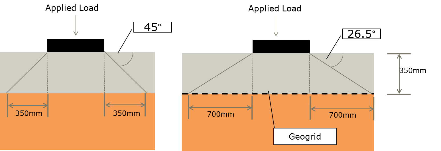
Figure 5.1. Tensar approach to load distribution.
The Tensar Application Suggestion states that for a 1 m2 area loaded with 200 kN a 350 mm thick road construction would distribute the load over an area of 2.89 m2 with a resulting applied bearing pressure of 69.20 kN/m2. In the case of the upper level of Peat this may have been acceptable but this neglects to allow for the very weak deposits in the saturated zone. [A quick use of Bousinesq would suggest that the underlying weak strata are over-loaded]
The proposed construction method involved laying the geogrid directly onto the top soil and existing vegetation and then building up the road. This would constitute a floating design and as such is unlikely to have been approved by Vestas. The ‘Crane Pas and Site Compound Construction Detail’ on the BSW design drawing would suggest excavation of 350mm of material, laying geogrid and then building the road up level to the existing ground level. The design drawings, marked ‘Tender’, include the note shown in Figure 5.2.
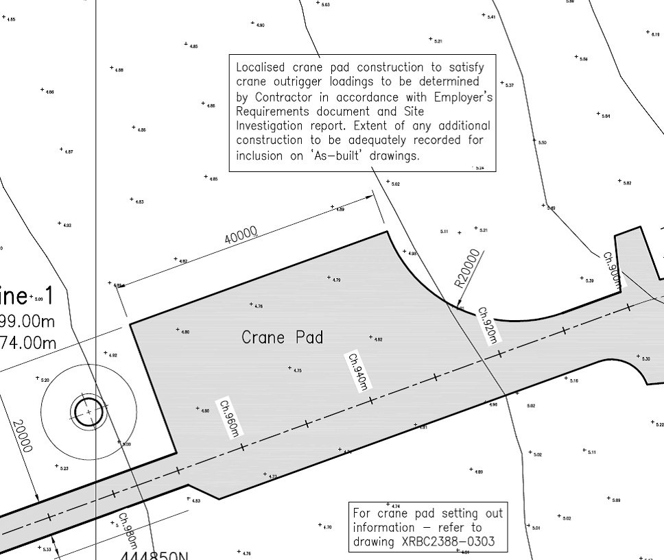
Figure 5.2. Note included on the tender drawings.
5.4. Summary
The outline design included on the tender drawings by BSW was not fit for purpose for the following reasons:
- The Tensar design was only an Application Suggestion requiring further detailed design prior to issuing for construction. The Application Suggested was not fit for purpose because:
- It was a floating construction and as such unlikely to be approved by Vestas. It seems that BSW modified the Tensar construction method to make it less like a floating road by excavating the road thickness into the Peat, this excavated through the stronger crust and therefore exacerbated the situation.
- Tensar conducted the design based upon tenuous CBR information correlated to undrained shear strength and failed to take into account the significantly weaker layers underneath the upper Peat.
- The design loading was based upon a minimum value found in the Vestas document which was clearly caveated to state that site specific loadings were required for detailed design.
- It ignored the recommendations of the GIR to remove all the Peat in order to provide a more reliable formation material.
BSW knew the above was only an initial design primarily because of the lack of a detail lift plan for the erection of the crane hence the clumsily worded note on the design drawing.
Askam had access to all the documentation available to BSW and as the design and build contractor hold ultimate responsibility for the design of the works. Without a written agreement from Vestas accepting the design of the crane pads, the requirement for which is clearly stated in the document referred to in this report, Askam should never have progressed with construction.
Things fall apart…
There is a genuine BP post on the way, just as soon as I finish this TMR…until then some comments on the following would be appreciated. I have been providing some engineering advice to my old housing association in Woolwich over the last 3 or 4 years. Over Christmas there was a roof leak in one of the upstairs flats caused by the structural failure of a roof air vent as per the pictures below.
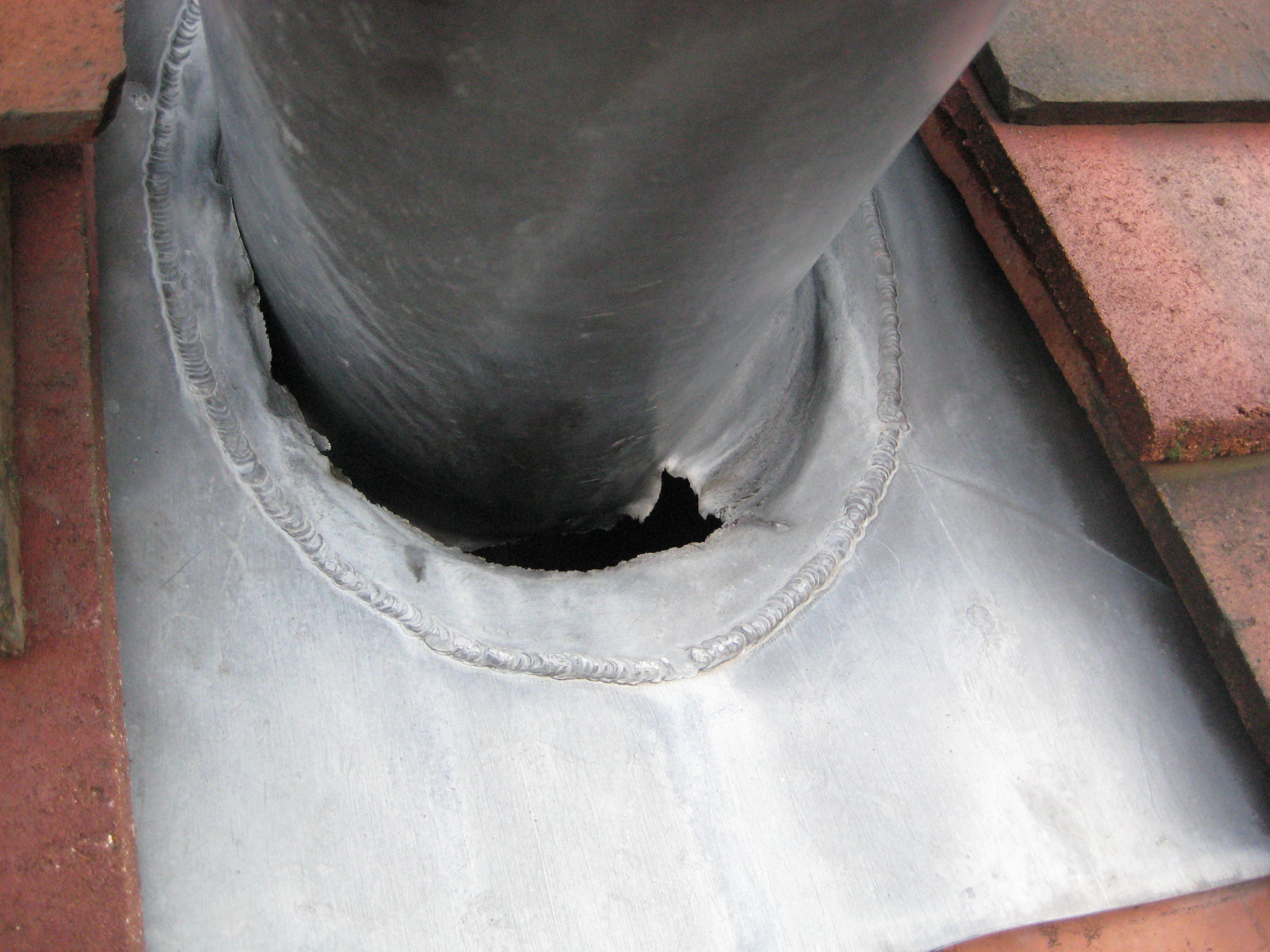
The only thing holding the vent in place was the lead flashing which, under wind loading, has failed quite catastrophically as can been seen above and below.
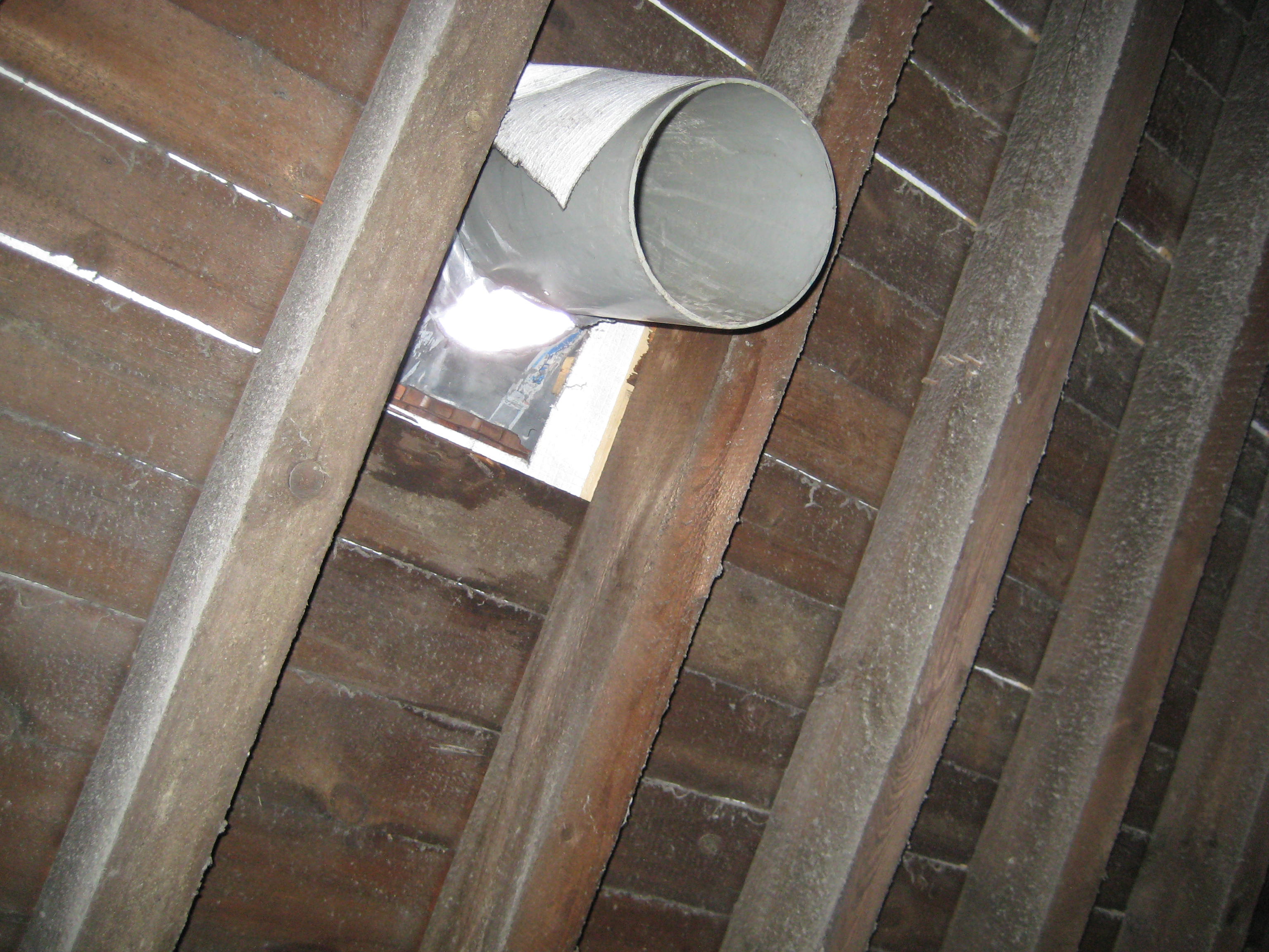
Below is an example of the stack arrangements on the roof, the third stack in is identical to the failed one and is clearly already starting to buckle.
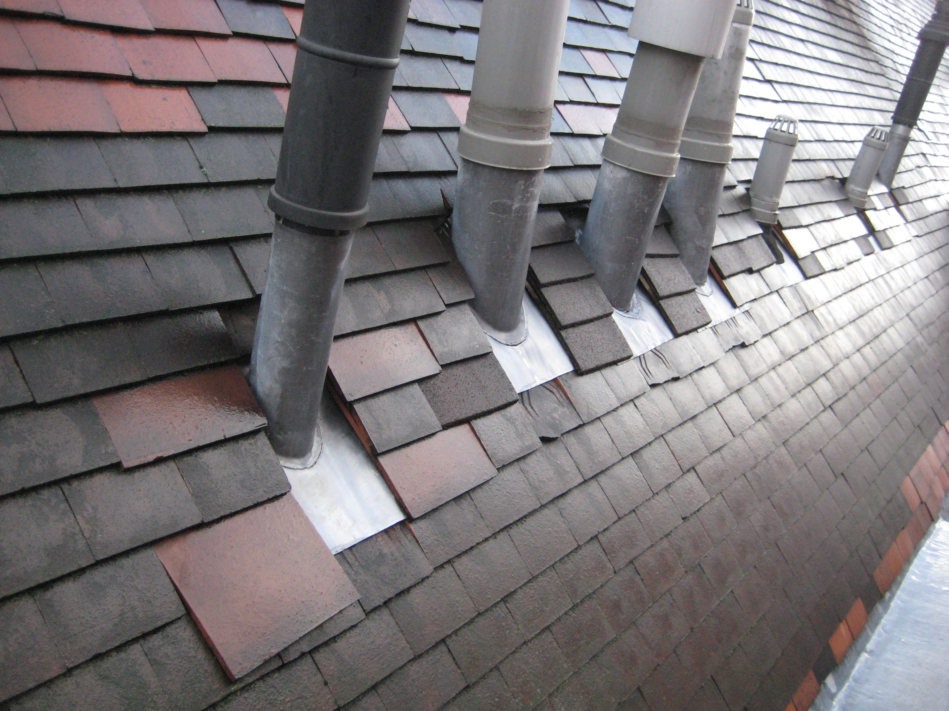
Below are pictures from the front and side of the development. The stacks are positioned in the valleys of the roof and can’t be seen in the photos, but it gives you an idea of the size and shape of the roof, the elevation in particular.

My first thought would be that stacks at this elevation, on a hill and overlooking the Thames and a lot of flat space, would be subject to near constant wind loading. I would have expected something a little more robust holding them to the vertical than a few mm of lead flashing. However, I am not expert in roofing design and my first assumption is that this would be a standard building practice that, in this case, should have avoided/improved upon by the architect/site engineer. I have advised the Residents Association request that Gallions inspect the remaining flues and vents as I am sure that this is going to be an issue common to most of them (especially going on the jaunty angles in the photos).
There is mounting evidence that the developer has cut numerous corners, which the housing association (Gallions, now Peabody) failed to pick up on when taking over the building on completion. I am interested in your views as to whether this would be another one…
Ballinyoo Bridge Replacement
It has been a long Christmas break. Partly because BG&E extended their close-down period to 3 weeks, but mainly because we had both sets of parents over. It has been like trying to herd deaf, incontinent cats for 2 weeks. I have been at my wits end, and I have actually been glad to get back to work.
The start of the new year has brought with it a few new projects for BG&E, not many but the year is still young. It is still quite evident that the company is scratching around for work in order to fill time until something more substantial comes along. At present I have continued to work on culvert sizing reports for the Main Roads WA panel contract, I am still waiting on a response to a proposal to upgrade a culvert crossing in the Perth Hills (though this may be shelved by the Department of Parks and Wildlife whilst the deal with the fallout of the recent bushfires), and I have recently been handed management of a bridge replacement proposal in the middle of nowhere.
The Shire of Murchison strangely prides itself on being the only Shire in Australia to have no Township. With a land mass of 50,000 square km and a population of 117. The Ballinyoo bridge replacement project was initiated by MRWA in 2006 but now in 2012 on it’s 4th iteration it looks like the planets have aligned and it’s a goer!

Only 9 hours from mine
The main reason for now replacing the bridge (aside from it’s amazing state of disrepair) is ironically due to the Shires isolation. The government will be starting the Square Kilometre Array (SKA) project to place loads of satellite telescopes in the area where there is limited ambient light interference. They expect that the construction traffic alone will increase the roads daily vehicle use to a whoping 15 from a mere 3. Couple to that the fact that it is only serviceable for 8 months of the year when not inundated by the massive 700m3/s flows it regularly expects in the wet season, and you wonder why they are bothering. The bridge was the first precast concrete bridge in WA, and though it is 85years old, the initial quality was pretty poor standard and it has required significant maintenance just to keep it open over the years.
My main effort this week has been baselining where the project sits with BG&E. One of the main issues has been what the client actually wants. A 20year dry serviceable structure has been requested, though not formally. It would be easy to provide a simple design to achieve a 20 year dry bridge but due to a total of a 2400m floodway along the sides of the structure with a dry serviceable return period of 7 years, it hardly seems worth it. I organised a kick start meeting with anybody who had corporate knowledge of the project which was useful to keep all informed and for me to establish a route forward. Following the meeting I have been in comms with the client to backbrief them my recommended scope and to confirm the findings of my previous work review, in the hope that once confirmed, I can produce an accurate proposal for completing the work.
The project comprises 3 BG&E elements:
- Waterways – Design flows and stage heights to set bridge soffit height and culvert sizes
- Civil – Approaches, road alignment, culvert
- Structural – Substructure and Superstructure
Waterways
The catchment area is pretty huge at approx 82,300 km2. It’s flood flow at 20 year return period is approx. 750m3/s at a height of 246.7m AOD. When the deck height is currently 245.9m AOD this is a problem as the 5 year period is actually higher. The issue with raising the bridge to meet the 20 year period is that to raise the bridge means to raise the road, which will increase the headwater upstream of the bridge and therefore mean that the deck will need to be higher still. An option to reduce this is to install culverts into the approach rises to lower the stage height. By placing a culvert through it attenuates the storage somewhat and allows a lower road/bridge. It is an iterative process that can only really be obtained accurately using computer software. That said, design is based on historical flood measurements, estimations of flow, surveyed levels and guessed manning’s numbers so ‘accurate’ is a pretty vague word! The question remains whether it is financially viable to raise the road height along the whole 2.4km alignment.
 Civil
Civil
Once the bridge height is set and the intent for the alignment is established (floodway/culvert/nothing), the design of the approach embankments and road can be completed. Nothing much has been done on this yet, as they originally worked up 2 alternative alignments in the 3rd iteration when the existing alignment was off the table. The client now wants it on the original alignment. This is difficult for BG&E as the project is currently in the proposal phase and therefore not billed. This deficit will be made up in the fee if won.
Structural
The design at present will be a 72m proprietary Rocla bridge system (so not much in the way of superstructure design) with a piled/rock socketed foundation that will be connected to the newly raised road by 2 earth bund approaches with an additional culvert to maximise the dry serviceability period.

Rockla Bridge Deck System
The original plan was to use the Rocla precast spun concrete piles, but due to them cracking on a previous build, standard circular concrete piles or H piles will be driven. These piles form the piers that join with the headstock – this is something I need to look into this week.
Still a long way to go on this one. Not entirely looking forward to the site visit, but at least I will get a bit of red dust on my boots. Finding it particularly hard to pin anyone down on anything, so I have started a decision register that I can roll out at meetings to track past and current decisions made.
Please tell me this is a worldwide phenomenon!
Has anyone else noticed a tendancy for the entire office to get up to go to the toilet between 1650 and 1657? It seems that everyone is so bored all day long they don’t even want to urinate on their own time for fear that it will delay their exit from the office. Please tell me it happens everywhere.
Retaining wall supported with a buttress
It seems I do have time to add another blog.
As I have discussed in previous blog, the pile group for the buildings were next to a railway track. In order to excavate the ground next to the viaduct, a retaining wall was required. However the retaining wall could not be supported by props as there was nothing to prop against. A a result the retaining wall was supported by buttress’.
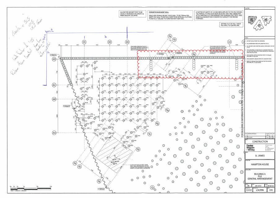
As you can see from the drawing above, the buttress’s are spaced by 13m and comprise of 4 x male piles and 3 x female piles. The spacing between the males are 1300mm. The original design allows for the female buttress piles to be installed to the depth of the retaining wall piles, allowing the male ones to go deeper to provide the stability. I was interested to find out how they had designed the buttress wall toe depth for the male piles. Here is a quick sketch of the way I calculated the resistance of the buttress piles.
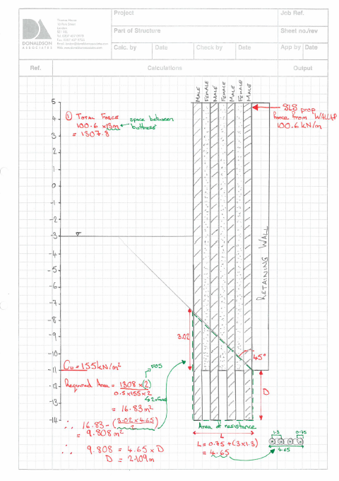
It seems to agree with Skanskas approach. However they had a toe depth of 11.6m, different to my 13m. I soon realised that they had made an error in their calcs, they had forgotten to work out the area of resistance correctly. Secondly I was concerned that if they were using L=4.65m, they should extend the length of the female piles to the same length as the male ones. The soil that is caught between the male-male piles would not create the same friction as male female pile combination. These factors have gone back to Skanska, I await their decision. I hope my suggestions are correct!
Piling Cat 3 check complete
This is only my second post since being on Phase 3. The reasoning for it has been this bloody Cat 3, external check, on a pile design. The deadline for it was the 14th, and then I took some time writing up my TMR 4, which happens to be about piling.
The pile design was completed by Skanska, for 3 x 30 story buildings. The buildings were sandwiched between the River Thames and a 4 track main route into Waterloo.
The first considerations that I looked into where the geological conditions. As London is located on, what use to be a sedimentary basin some 66 million years ago, much of the immediate ground is made up of clay. The clay is formed of both London Clay and Lambeth Group. What does that mean for the design? After some detailed revision of John’s notes and a little research I released that there is the potential for two events: Overconsolidation and Artesian pressure. The next question was, how can these effect the design.
Overconsolidation in the clay meant that there was a high probability of anisotropic properties in the soil, this translated into a Overconsolidation Ration (OCR) of potentially 5-6. Hence I could have differing values for soil properties such as strength and stiffness, depending on the plane in which I was analysing. This also meant that as we excavated the soil, we could expect much more swelling than would otherwise be expected. This would cause excessive swelling, much more than would be expected from elastic swelling. Hence there would be heave on the piles, however the piles would experience differing amounts of heave as the stiffness of the soil would be greater, the deeper the pile was. This would cause a stretching effect on the pile, which would need tension reinforcement.
Secondly if Artesian pressure was present in the lower aquifer, which is contained in the Thanet Sand and chalk, there might be a need for dewatering to reduce heave on the piles. Clearly this would only be necessary if the piles where penetrating the lower aquifer, hence they would have to be long piles. As a side note, the Shard has 200ft piles which did penetrate the lower aquifer, however there was no Artesian pressure in that area (due to historical welling taking place).
On top of both of these geological considerations, I was dealing with Clay. Therefore I had a long term and short term analysis to consider. In the short term (undrained) I would be using total stress parameters, such as Shear Strength (Su). In the long term (Undrained) I would be using effective stress analysis and properties such as Effective Cohesion (C’) and Effective friction Angle.
I knew that the pile resistance was calculated using the Shaft Resistance and the Toe bearing capacity. Hence I needed to use:
Shaft resistance = Cu N
Toe bearing = alpha.Cu or a more accurate effective stress analysis equation which I can’t write down as I haven’t got time (John you will see it in my TMR)
So the first step was to conduct the same stages as we did on Ex Cofferdam. Look at the boreholes, compose a worst case scenario of the cross-section the piles would be penetrating. From there, I created a spread sheet. The columns included, depth, depth of strata, soil properties, end bearing resistance, shaft resistance etc. The next step was to apply the factors from EuroCode 7. This gave me the ULS 1, ULS 2 and SLS combinations. It turned into a mammoth spreadsheet, I might get it framed.
I then looked at the actions on the piles, from the column loads. Applied the factors giving me SLS,ULS1, ULS2 and compared these to the previous results. If the actions where smaller than the resistance from the soil, the piles where OK.
The last check was the structural capacity of the pile. I needed to check the reinforcement in compression, bending shear and tension (as previously described). This required the use of the Broms equation, to turn the horizontal loads (given in the piling schedule) into moments. For each check, I used Eurocode 2 and Rich Farmers notes on column design to guide me through. I designed the piles as short stocky piles, as the effective length was minimal as the soil supported the column/pile the entire length. As John Moran suggested, as long as post holing does not occur, this design method seemed appropriate.
The next stage was to analyse the retaining wall, which was supported by buttress’. I have got time to do this justice, so I will explain this in the next blog next week. It was surprising interesting, so I will produce a few sketches.
Burton out!!!
