I don’t just complain about civilians…
I do some work too….
Actually writing down stuff that sounds a bit clever seems to be de rigueur at the moment so I thought I better make a bit of an effort, I can’t be flippant forever and RF is right CPR is somewhere on the horizon. The bridge foundation I’ve been working in in the final stages but it’s not been on my desk for a week or so. Much of last week was spent preparing a basement impact assessment for a domestic property in Camden, quite interesting (in an engineering sense) and not too many numbers thankfully, that’s now with one of the environmental guys to do the flood risk assessment and awaiting RFIs to be returned from the developer. Something that’s been hanging around in the background for a while has been a gone wrong wind farm, thankfully not gone wrong because of us but Ramboll have been called in to provide expert witness services, I think we could be prosecuted under the trade description act as I’m the only one from geotechnics working on it currently and I can’t claim to be an ‘expert’. The initial request was to do with the actual foundations of the turbines themselves there were doubts raised during the checking process (which was complete after construction commenced) this didn’t progress very quickly initially although it has since landed back on my desk, thankfully with the help of Repute an uber pile calculation programme and the structures modelling software I’ve not had to wrestle with ‘piling in weak rock’ as the piles go down through peat and glacial tills to Sherwood Sandstone underneath. The second part of the contract was to conduct a check on the crane foundations that were constructed for the build phase. In short the foundations were subject to a litany of design problems and the tender submission was woefully inadequate although the tender drawing alluded to this the design and build contractor never really developed the solution and the ‘typical solution’ became the ‘for construction’ solution and the contractor progressed without the stipulated written consent from the turbine manufacturer. That’s the short version, getting this far along has required an awful lot of reading and cross referencing of documents and has felt a little like doing another TMR. Below is the whole report that I have prepared so far on the initial design and will start on the remedial works tomorrow. I won’t blame you if you don’t read it.
1. Introduction
1.1. Background
Ramboll have been engaged as an expert witness commissioned by Hill Dickinson on behalf of BSW Consulting to carry prepare a preliminary report in relation to the design of the crane platforms used to erect the wind turbines at Orchard End Wind Farm.
1.2. Qualification of Authors
The qualifications of the authors of this report are summarised below:
Rich Phillips, Graduate Engineer, BEng
2. description of project
2.1. Location
The site is located at North Wood’s Hill Farm in Wyre Borough, Lancashire. The area is arable land which is drained by a number of ditches discharging into the surface water channel known as the Momen Gutter.
2.2. Wind Farm Development
To date 2 wind turbines and associated support infrastructure, control buildings and access routes have been constructed. The client for the development was REG Windpower Orchard End Ltd, part of the REG Windpower Ltd group with Askam Construction Ltd appointed as the design and build contractor. The initial tender designs for the scheme were provide by BSW Consulting Exeter Ltd, BSW were later appointed by Askam although never formally novated.
2.3. Issue
BSW’s design responsibilities included the working platforms used by the turbine provider, Vestas, to operate the cranes used to erect the turbines. In support of the design of the scheme they were provided the Ground Investigation Report (GIR) supplied by Ground Investigation (Wales) Ltd who had been engaged by REG to provide the necessary geotechnical information for the design of the scheme.
In Dec 12 it became clear that remedial works were required on the crane pads, BSW provided a design and remediation began in Mar 13. During the erection of Turbine 1 the crane outrigger suffered excessive deflection and the work was aborted. As a result of this a piled solution was pursued at the request of Askam.
3. References
The following sources of information have been used in this assessment:
- Email Sarah Naylor/Paul Jackson, dated 24 Dec 13, Ref SJN.940401.6129.
- Geo-Environmental Site Assessment Report, dated Jun 11, Ground Investigation (Wales) Ltd.
- BSW’s privileged report (we have been instructed to treat this as sensitive).
- Application Suggestion for Orchard End Wind Farm from Tensar International Ltd supplied to BSW, dated 7 Dec 2011.
- Working Platforms for Tracked Plant, BR 470, 2004, Building Research Establishment.
- BSW design drawings (Tender):
- Site Construction Access Track Layout, Sheets 3 & 4, dated Dec 11.
- Road, Crane Pad and Hardstand Specifications for Vestas Turbines V80-V90-1.8/2.0MW V82-1.65MW and V90-3.0MW, dated 9 Mar 10, Ref 0002-0277 V03
4. pre-design information
4.1. Ground Investigation
The GI conducted 2 No boreholes located in the centre of the turbine foundations with a larger number of machine excavated trial pits completed under the foundations and along the proposed access track alignment. Soil strength parameters were determined through the use of:
- SPT.
- Shear vane tests.
- In-situ CBR correlation tests.
- Laboratory testing including tri-axial, oedometer, particular grading and Atterberg tests.
The outline sequence of strata and design parameters found in the borehole under Turbine 1 are detailed in Table 4.1.
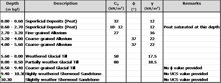
Table 4.1. Sequence of strata encountered in Borehole 1.
4.2. Qualitative Assessment
Section 6 of the GIR provides assessments and recommendations for each element of the scheme and in particular highlights the geotechnical hazards on site; the first hazard detailed in the report is the presence of the low strength deposits of peat and alluvium. The key assessments and recommendations relevant to the Turbine 1 crane pad made in Section 6 are as follows:
- Water was encountered in the low lying areas during excavation between 0.6m and 0.9m below ground level. (Ref 6.4.5)
- ‘Hand vane tests conducted within the upper Peat horizon indicted an undrained cohesion of typically 30 kN/m2, reducing to around 10 – 20 kN/m2 within the saturated zone below around 0.6m depth. Values of undrained cohesion reduced further within (sic) increasing depth, to values as low as 6 – 8 kN/m2. The values….indicate that strata of very low-strength and high compressibility occur beneath the loaded zone of the crane pads.’
- CBR correlations across the site frequently returned values below 1%.
- The crane pads must not be found on the Peat, instead the full thickness must be excavated in order to reach the material below.
- The recommended figure for acceptable bearing pressure on the Fine-grained Alluvium was 35 kN/m2 if this loading could not be achieved then excavation to the Coarse-grained Alluvium should take place with a maximum applied pressure of 50 kN/m2.
4.3. Summary
The assessed soil design parameters combined with the qualitative assessment of GI (Wales) indicate the presence of a slightly stronger ‘crust’ in the top layer of the Peat above the saturated zone. The material below the crust is significantly weaker and unpredictable, a foundation design might be suitable for the upper layer but the pressures applied to the strata below might exceed the allowable bearing capacity.
5. Design approach
5.1. Design Loading
BSW based their initial calculations for the design loading on a public document published by Vestas (the turbine manufacturer). This document explicitly states:
‘This document is not sufficient in and of itself to construct…Crane Pads…and must be supplemented for each project and site before construction work commences….
The exact design of … Crane Pads… must be agreed with Vestas in writing prior to start of construction.’
This document stipulates the minimum bearing capacity of the crane pad must be 200 kN/m2 unfactored. It also states that ‘floating’ designs are unlikely to be acceptable. The document continues to establish the minimum physical dimensions of the crane pads.
5.2. Tensar Appointment
As part of the design development BSW employed Tensar Ltd to provide designs for the access tracks and crane pads. In support of this request elements of the GIR and the Vestas crane pad design document were provided to Tensar, archived email evidence of this has been provided by BSW. The sections of the two documents mentioned had significant sentences and values highlighted, specifically:
- CBR values quoted in the design report.
- The value of 200 kN/m2 as a design load for the crane pad.
[Crucially] The highlighting did not include:
- The recommendation to remove all the underlying peat.
- The very low undrained shear strengths of the Peat and Fine-grained Alluvium which provide a more representative value compared to CBRs.
- The fact that the 200 kN/m2 was unfactored (although this was later allowed for with a lumped factor of safety).
- ‘Floating’ designs are unlikely to be approved.
5.3. Tensar Solution
Tensar provided their Application Suggestion to BSW on 13 Dec 11. The document stresses that it is not a detailed design and that construction should not commence on the basis of it alone. In the main the document seemed aimed towards highlighting the potential reduction of construction effort, and therefore cost, with the incorporation of a geogrid.
The Tensar solution provided calculations based upon a CBR value of 1% which they have equated [by an unknown method] to an undrained shear strength of 24 kN/m2. The design utilises the TriAx geogrid and asserts that the load distribution will double as a result (Figure 5.1).
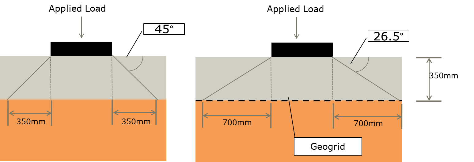
Figure 5.1. Tensar approach to load distribution.
The Tensar Application Suggestion states that for a 1 m2 area loaded with 200 kN a 350 mm thick road construction would distribute the load over an area of 2.89 m2 with a resulting applied bearing pressure of 69.20 kN/m2. In the case of the upper level of Peat this may have been acceptable but this neglects to allow for the very weak deposits in the saturated zone. [A quick use of Bousinesq would suggest that the underlying weak strata are over-loaded]
The proposed construction method involved laying the geogrid directly onto the top soil and existing vegetation and then building up the road. This would constitute a floating design and as such is unlikely to have been approved by Vestas. The ‘Crane Pas and Site Compound Construction Detail’ on the BSW design drawing would suggest excavation of 350mm of material, laying geogrid and then building the road up level to the existing ground level. The design drawings, marked ‘Tender’, include the note shown in Figure 5.2.
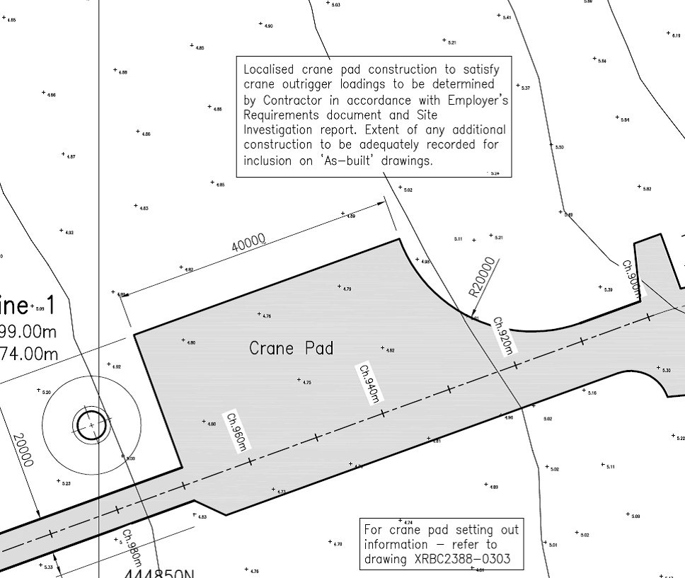
Figure 5.2. Note included on the tender drawings.
5.4. Summary
The outline design included on the tender drawings by BSW was not fit for purpose for the following reasons:
- The Tensar design was only an Application Suggestion requiring further detailed design prior to issuing for construction. The Application Suggested was not fit for purpose because:
- It was a floating construction and as such unlikely to be approved by Vestas. It seems that BSW modified the Tensar construction method to make it less like a floating road by excavating the road thickness into the Peat, this excavated through the stronger crust and therefore exacerbated the situation.
- Tensar conducted the design based upon tenuous CBR information correlated to undrained shear strength and failed to take into account the significantly weaker layers underneath the upper Peat.
- The design loading was based upon a minimum value found in the Vestas document which was clearly caveated to state that site specific loadings were required for detailed design.
- It ignored the recommendations of the GIR to remove all the Peat in order to provide a more reliable formation material.
BSW knew the above was only an initial design primarily because of the lack of a detail lift plan for the erection of the crane hence the clumsily worded note on the design drawing.
Askam had access to all the documentation available to BSW and as the design and build contractor hold ultimate responsibility for the design of the works. Without a written agreement from Vestas accepting the design of the crane pads, the requirement for which is clearly stated in the document referred to in this report, Askam should never have progressed with construction.

Sounds like fun, Rich. These are good projects that will stand you in good stead beyond the course. Please bear in mind you will be at your most competent leaving the course so comments like “not too many numbers thankfully” are a little worrying. Not sure why you don’t think you have the confidence to deal with this type of problem.
That’s one hell of crane ‘pad’ The drawing seems to define the extent of a matress on which the crane and outriggers fit?
I guess that the plates beneath the outriggers become the foundations and then it’s
Boundaries
Properties
GWL
(as the risks)
In general the boundary beneath the plate will be 1.5 times the width/diameter of the plate ( becuase a shear failure will not extend any further)
It’s (sort of) an undrained case BUT
a) the stiffness of the peat may be so low that immediate settlement becomes a problem. This, as you note, is certain if you dig out the duri-crust!
b) If the shear surface extends into the alluvium….well you just can’t assume it would remain undrained-tricky!
The recommended values for allowable bearing capcicy appear to the the ‘q0Nq’ bit of the cNc+gammaNgamma+qNq (should be in your head as the bc equation) So looks conservative even with this crap beneath
I’d add CIRIA C703 (Hillary Skinner’s book) to your reference list – there are also a welter of BSI crane-thing pubs – but I’ve never read any of them…so good luck there!
Spectacular stuff!
As usual you are good value for money
Ah yes John, I remember the old cNc+gammaNgamma+qNq equation fondly! Good times!
Well done Columbo, it looks like you’ve got them banged to rights. By the way, I know what you mean by too many numbers; it’s not fear, but the fact that they rob you of your life. But hey that’s what we get payed for.
Jim
You seem to have missed the MInstRE of you post nominal letters, has it no value?… More seriously be careful about the expression Tensar Appointment and Tensar Design because, as you rightly observe, they may have been apporaoched for a suggestion regarding application of their products but will have done so without payment or appointment because this is what they will do for you in pusuit of sales. They will produce a design if appointed them but at a cost for obvious reasons. Unless your 5.2 is correct and they had a contract and were employed in which case sue them they were negligent in not asking for all relevant design information etc. but otherwise, do not make the same mistake that others have and suggest that Tensar were appointed or completed a design I would advise that all references to thier input should be adjusted to read Tensar information, advice or suggestion.
Next thought, You are being employed by Hill Dickinson on behalf of BSW the client to advise on the foundation design (right ?). Is you first sentence of 2.3 correct? If so your client has agreed to produce a design which their drawing acknowledges they have not. Problem! Question – what is they are asking you to do? Show that the suggestion made by Tensar was an adequate foundation in accordance with the GIR? This is a contractual and technical goldmine for reflection. Love it!
Rich
Excellent work – good stuff for CPR and your 4 k report if you need to include a second project – besides your site stuff
Regards
Neil