Archive
Train derailment at Stoke Lane on the 27th Aug 2013
This is a very short blog, as I don’t have time to go into detail. Yesterday I had a really interesting presentation on the factors behind the train derailment at Stoke Lane on the 27th Aug 2013.
Incident Overview
Nottingham train station was closed for a 6 week period, in this period company X tried to take this opportunity to lay some cables below the track (that was not operating as station was closed). In order to lay the cables they used some pipe jacking to lay a 1.2 m dia tunnel under the track. This required two shafts to be sunk, allowing the miniature TBM to be lowered into the shaft and jack the pipes in behind it.
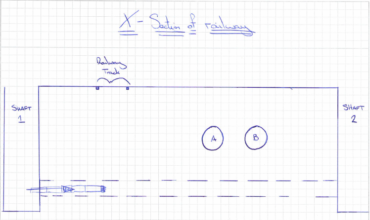
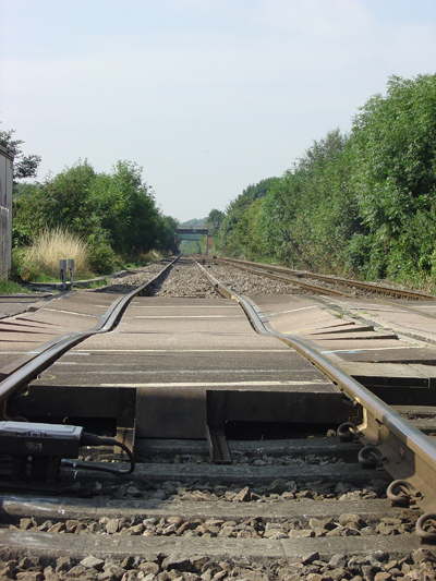
Several weeks later a train consisted of a class 66 locomotive and 30 bogied, tank wagons, loaded with diesel fuel. It was travelling on the up line towards Nottingham at a speed of around 53 mph (85 km/h) when the driver noted an irregularity in the track as he went over the crossing. Shortly afterwards, the trailing wheelsets of the 26th and 28th wagons derailed and ran for approximately 850 metres before the train’s brakes brought it to a stop, as air leaked from a punctured air reservoir tank. None of the other wheelsets were derailed. Both derailed wagons remained upright and there was no leakage of the diesel fuel but the track and some wagons suffered damage
Our involvement
As part of the Rail Accident Investigation Branch (RAIB), Donaldson Associates were asked to look into the method statement and design of a 1.2m diameter tunnel located directly below the area effected.
Findings
The findings are due to be released to the RAIB next month or so, however the preliminary findings are quite shocking. It appears that there was a number of factors that caused the derailment. I will try to explain just a few.
1) Most surprisingly, it seems that no one recorded the amount of spoil that came out the tunnel. It is now understood that twice as much spoil was removed compared to the volume of the tunnel. Where was this soil coming from? How did the contractors not understand that this was a serious concern?
2) The designers were not aware of the main line sewer pipes running above the tunnel until much later, after the tunnel design was completed. These sewer lines were carrying 4m3/sec of sewer, hence some substantial loading.
3) The depth of the tunnel was designed by calculating the live load on the rail way line, ensuring the crush capacity of the tunnel exceeded the live loading. It never factored in the weight of the soil between the railway and the tunnel.
4) The annulus (the space between the void created by the TBM and the concrete sections of the tunnel) of 25mm was not filled with grout or Bentonite. This would greatly increase the volume loss.
6) The volume loss in the design calcs was estimated at 1%, however empirical evidence shows it should have been around 2-2.5%.
7) The K value, that calculates the trough of settlement (Clay would be lower, gravel higher), used was 0.6, however for gravels it should have been around 1.2. This would have given a far deeper settlement in a more localised area.
8) Network rail (NR) do not allow works to proceed if the settlement is above 5%. If the volume loss and K values had been more realistic the settlement would have been around 7mm. Although this is nowhere near the 20mm settlement they experienced it would have been enough to stop the works in the first place.
9) Although the NR stipulate that there is to be no settlement in excess of 7mm, they do not stipulate any trigger levels. Additionally the company that monitors the tracks, recorded 20mm settlement, but didn’t do anything about it. There was no process in place to deal with the consequences.
10) The monitoring of the line only monitors the track. The soil below is not monitored. On inspection the track was spanning 700mm voids wit a span of 2m. No one was even aware of it.
As you can imagine the repercussions of this will be vast. The asset managers within NR are sure to have a busy time over the next few months. As a side point, the asset manager that signed off the works wasn’t even a ICE member let alone a CEng. Infact he had some random degree, yet was signing off works left right and centre. Sounds like he should join the RE (it sounds very familiar to my early days in the RE).
Dodgy looking columns.
Having completed and submitted the tender for the North Eveleigh 11kV relocation project the other week I moved on to two other projects which are both part of the Rail Panel work. This panel consists of three consultants for which SMEC are one that get the honour of submitting proposals for various maintenance and upgrade works for Sydney Trains. Although some jobs are rather chip shop there are plenty of gems on offer and as the panel is a three year agreement it has provided a steady revenue for the rail structures team which I think was greatly appreciated last year.
The first is another tender of what Sydney trains call a Request For Proposal (RFP) for some building modification works on a substation about 50km north of Sydney. I attended the site inspection and even to me semi-trained eyes it looked like a fairly straight forward job. The intention is to remove certain outdated equipment and provide an admin room in its place as well as a seperate extension on the opposite side of the building to house a new DC switch room. I have engaged an architect, surveyor, building services consultant, building code compliance consultant and the pertinent in house specialists and will work on the proposal next week for submission on Fri. Thankfully there is no electrical work to be carried out like the last tender so I hope to control costs a little bit more to get a competitive price together. I’ll update more on this next week I am sure.
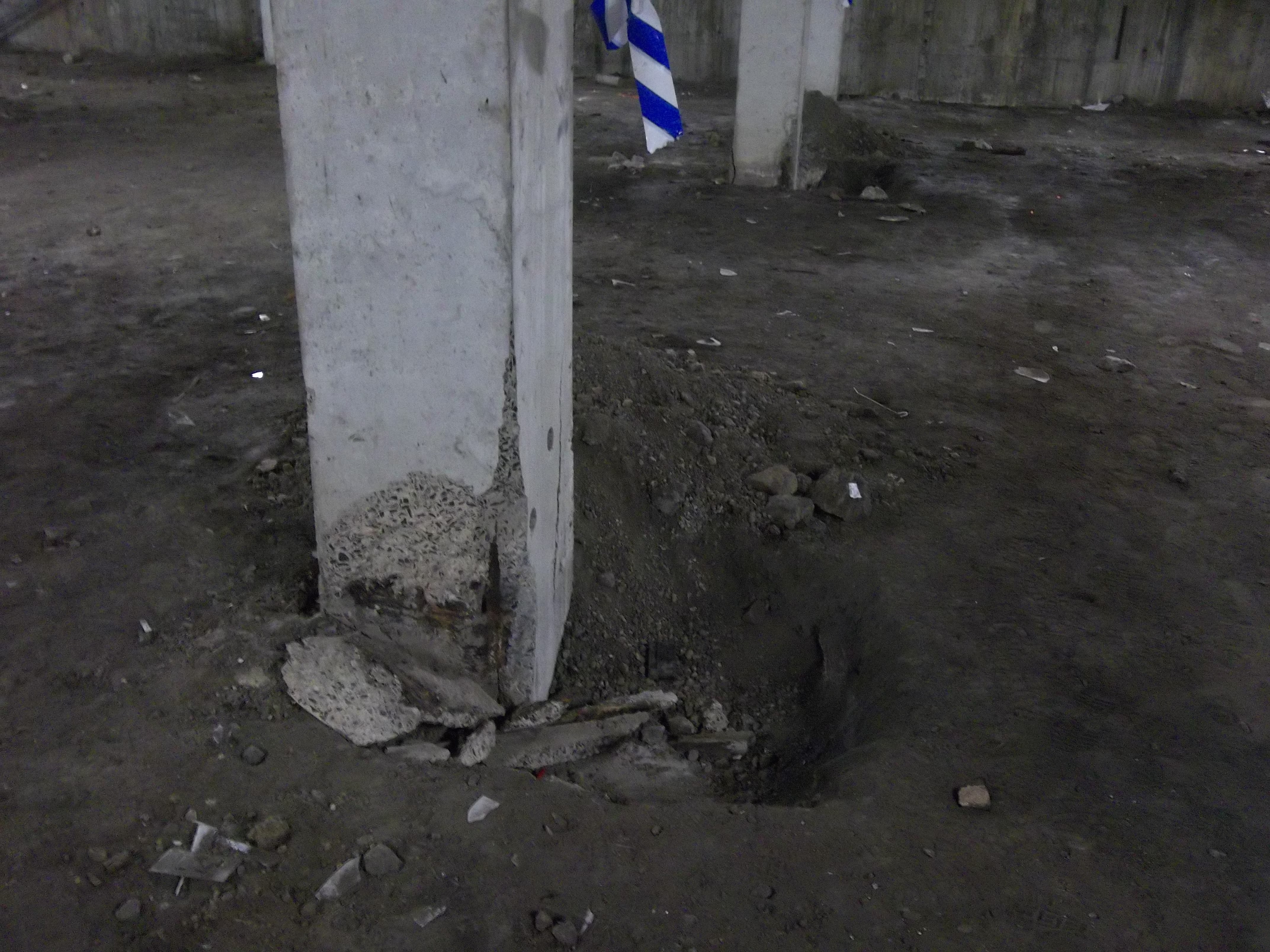
The second project moved my focus back to Eveleigh but on the other side of the tracks where a maintenance centre is located. Another consultant from the panel had originally been engaged to conduct an investigation of the basement columns where corrosion and subsequent concrete spalling had been observed. The initial concern was whether there were any structural capacity issues. We were asked to comment on the report findings and state whether we agreed with them. The original report concluded that up to a 50% loss of reinforcement section would be acceptable and that the current imposed loadings were not likely to be near the design loadings. The actual level of corrosion has not been detremined and although I haven’t visited the site the photos I have indicate that it is quite bad in places.
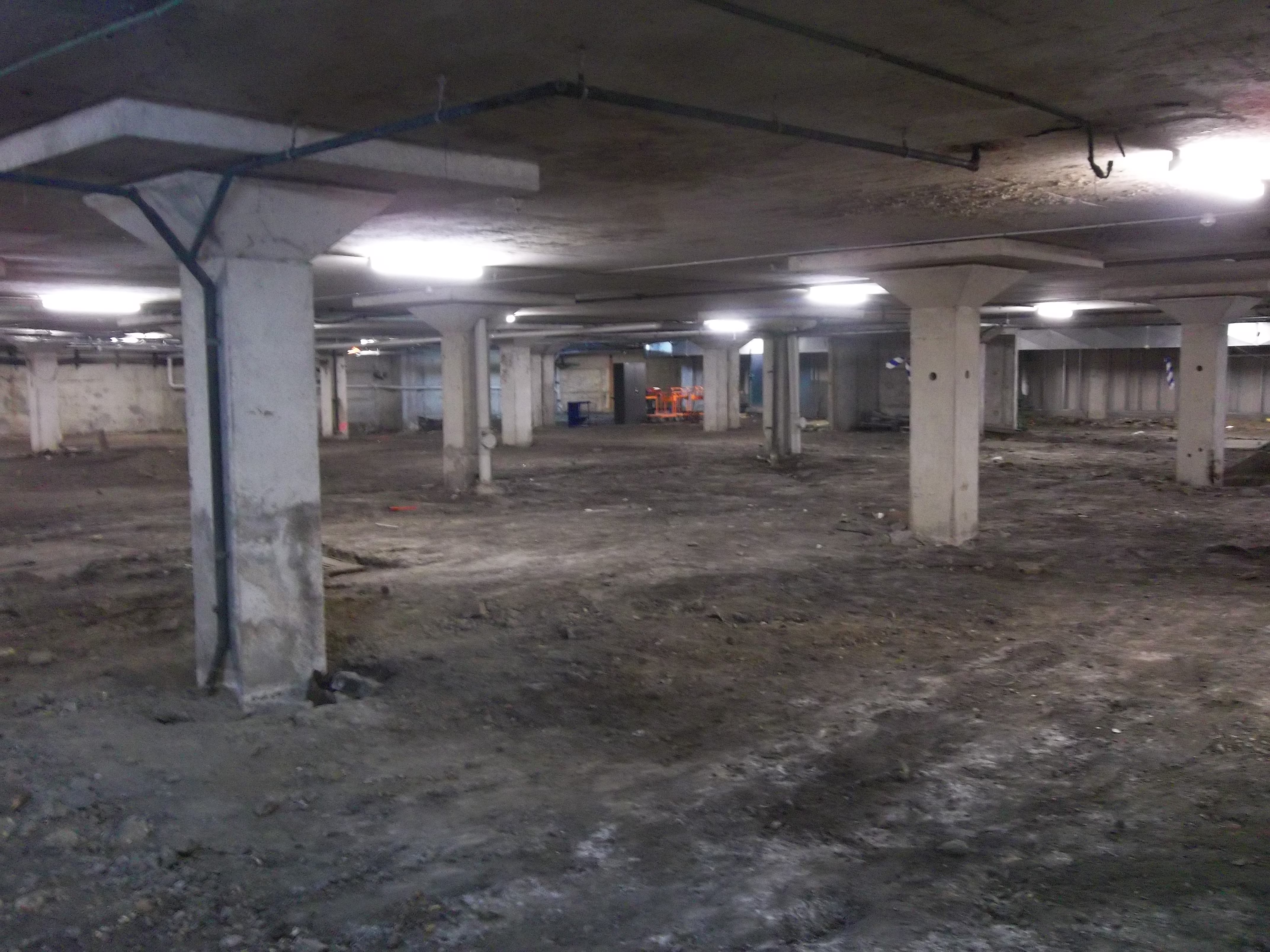
Initial thoughts were that stray current may be the cause of the corrosion. The tracks run parallel to the depot and it was proposed that the piles were picking up stray current from the tracks and conducting it to a point closer to the substation. However, the corrosion has only been observed above ground level and when the ground to the top of the pile cap was investigated there were no signs of corrosion. It must be pointed out as can been seen from the photos that the area of concern is approximately half the footprint of the building and there is no ground slab, the other half of the basement is in good condition (has a floor) and is used as an underground car park.
![train1[1]](https://pewpetblog.com/wp-content/uploads/2014/01/train11.gif)
Apparently, the rate of corrosion from stray current is 9kg/Amp/Year. When iron corrodes by stray current, or by other means, the iron ions have to combine with anions which is commonly oxygen, therefore the corrosion product of iron is generally iron oxides or rust which are insoluable. However, the rate of diffusion of oxygen into concrete can be slow and insufficient to combine with the quantity of iron ions being produced. This means the iron will combine with other anions such as sulphates, chlorides etc which are soluable and so no visible corrosion product exists except a ‘shiny’ surface. The disadvantage of this is that severe corrosion and loss of reinforcement section and structural capacity can occur before corrosion has been identified. The exposed reinforcement shown in the pictures is all covered in rust and so it was assumed (by a specialist stray current consultant) that stray current was not a major factor in the reinforcemnet corrosion but it could have occured after. As a result I compiled a report (more of a memo really) that proposed firstly a Cathodic Protection system to treat the possible cause of the corrosion and a physical column repair method involving ‘jacketing’ the columns in a 150mm RC layer. A few days later the client responded saying that they do not consider the stray current as an issue (the basement is poorly ventilated and conditions are very humid), therefore they did not want to pursue the CP option (which in their eyes came with an unsustainable electric bill) but they asked for a refernce design for the jacketing option. At present I am working up the details for this option which will assume the existing reinforcement in the columns is not contributing and so additional reinforcement will be placed on the outside. This is likely to increase the current 457mm square dimension of a 2.6m long column to 757mm square which is one short, stocky column.
Going back to the initial structural capcity check, I did not agree with the previous consultants conclusion that 50% loss of reinforcements section could be accepted (I calculated, well mainly an excel SS calculated) that only a 25% loss would be acceptable. I thought this would be a bold call considering a technical director did the initial calcs it appears is was due to the assumed compressive strength of the concrete. They had assumed 25MPa but I had the benefit of using actual core samples that were tested at various locations which using the code (no. of samples, sdev and all that) I used a value of 19MPa. My issues with all this so far is that firstly the actaul state of corrosion or loss of reinforcement section has not been determined and it looks like it will not either so there is a lot of assumptions. The second is the cause, it appears that the basement conditions may be the primary casue but to my mind stray current has not been ruled out and could still be the cause because no intrusive testing has been carried out. The big fat caveat with my design proposal at the moment is that this could be a ‘band aid’ job and unless stray current is conclusively ruled out by measuring the presence of a current flow through the columns and the basement conditions are addressed then at some point in the future the reinforcement will corrode to the point concrete spalling again. In fact any new reinforcement introduced to the columns without addressing stray current will be anodic to the existing reinforcement and thus increase the rate of corrosion in the new reinforcement. I will update again next week on how it all goes.
The Impact of the Arctic Vortex in a Design Office
Since the end of the holidays the weather has been a touch on the chilly side. In early January there was even a frostbite warning for people venturing on to the streets and the public transport literally froze. So since the New Year there have been 5 snow days, a bank holiday and then my mentor took 3 days sick leave. Combine this with a week long delay to get the energy modeling software and the knock on effect is a delay in productivity. Not always a bad thing except I was hoping to write my TMR using my project as a basis. Now that is in, the tempo is picking up, naturally. The modeling is nearly complete and I am now working on equipment selection and looking at incorporating energy saving technology in to the design. The first is to use a variable refrigerant flow system as the primary heating system. This is an old Asian 50’s technology which is starting to become very popular over here because of its efficiency. The principle is instead of pumping heated air round a building in large inefficient ducts, you simply pump the refrigerant directly to the room it is needed in where a fan coil unit then blows over the expansion vessel producing cold air at the right condition. What is even more impressive is that the expansion vessel can be switched from cooling to heating with an automatic valve change. Even cleverer still as that all the fan coil units (up to 50 odd) can be linked and can become heat recovery units too so if a room is too cold, the refrigerant in a room that is too hot can be directed to the cold room without going through the compressor. The Compressor/condensor unit is kept out side, so no mechanical room needed, and is about the size of a large fridge. As the building is aiming to get big points for green technology this is looking like a good system. The second design is for a Solarwall heating system. Placed on the SE/SW wall of the building this is free heating for relatively little investment ($20,000 for 2000 square feet) provides nearly free heating. A semi permeable polycarbonate shell heats the air, through solar energy, against the black wall which rises up the wall and is accumulated at the top where it is then pumped in to the space through a fabric duct with holes, like an ITC aircon duct. This will be great in the large warehouse area which VRF struggles to heat and often has the large loading door open. I have not worked out the energy produced but this was used in Harrisburg heat my warehouse too (see Matt Fry’s blog) where it has proved very effective.
I took the opportunity to visit my possible next project, Hale Hall. This former 1920’s barrack block was retro fitted with HVAC over the years before catching fire in 2006. Going round the building meant getting dressed in protective suits because of the presence of mould and bird poo. What was strange was that the fire damage was limited to the roof of one side but the whole building was water damaged and trashed. It was like walking through a time tunnel because the place simply had all the top secret stuff ripped out and was left. Not even desks had been cleared. Below are some of the odd HVAC designs I discovered.

Duct work that missed the obvious window opening
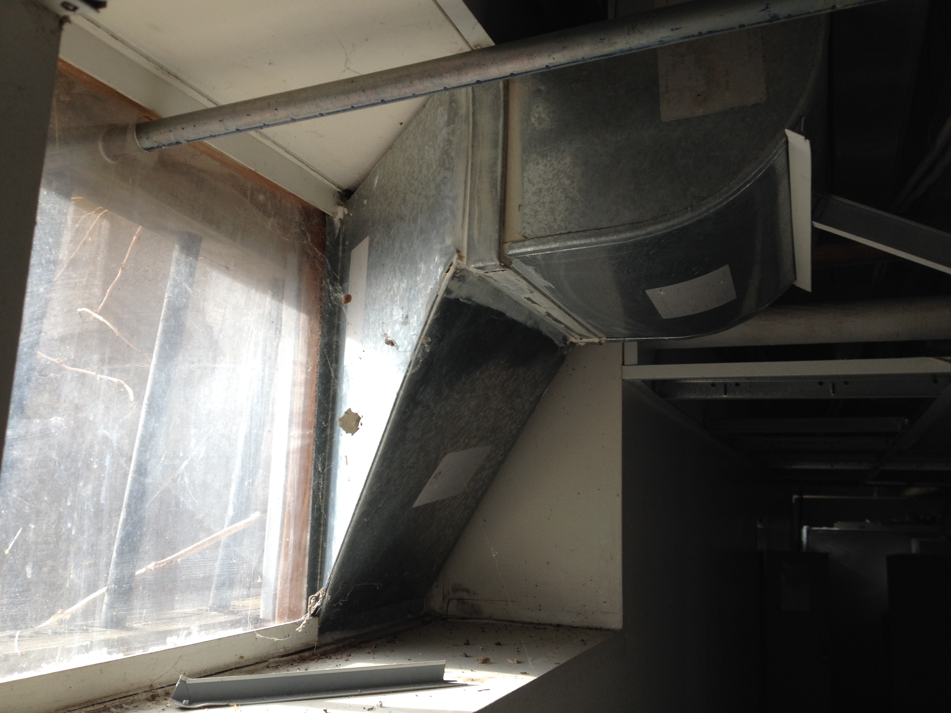
Another duct that fails to go through a window effectively
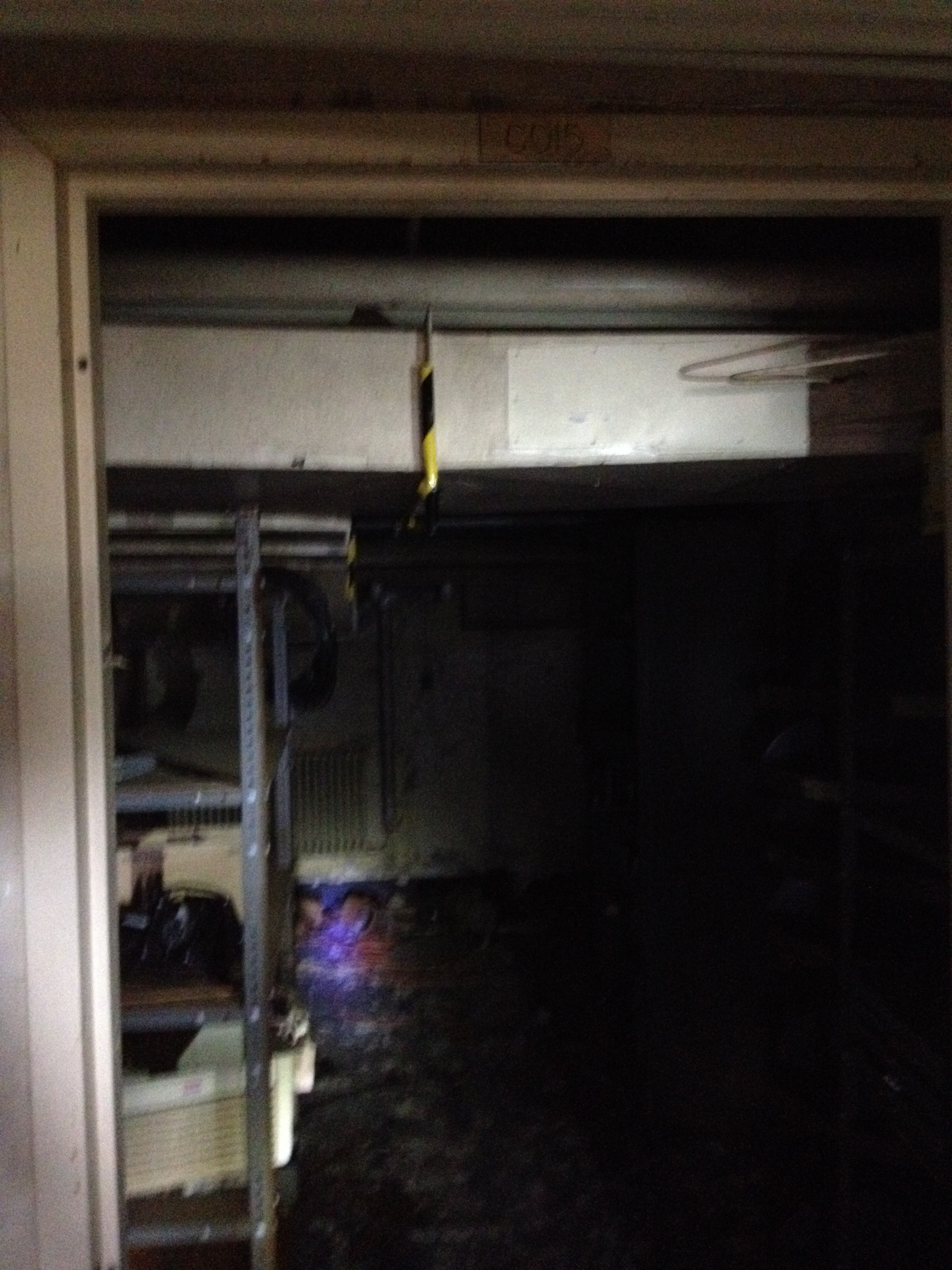
Duct work on other side of a door. Note the warning tape on the sharp joint
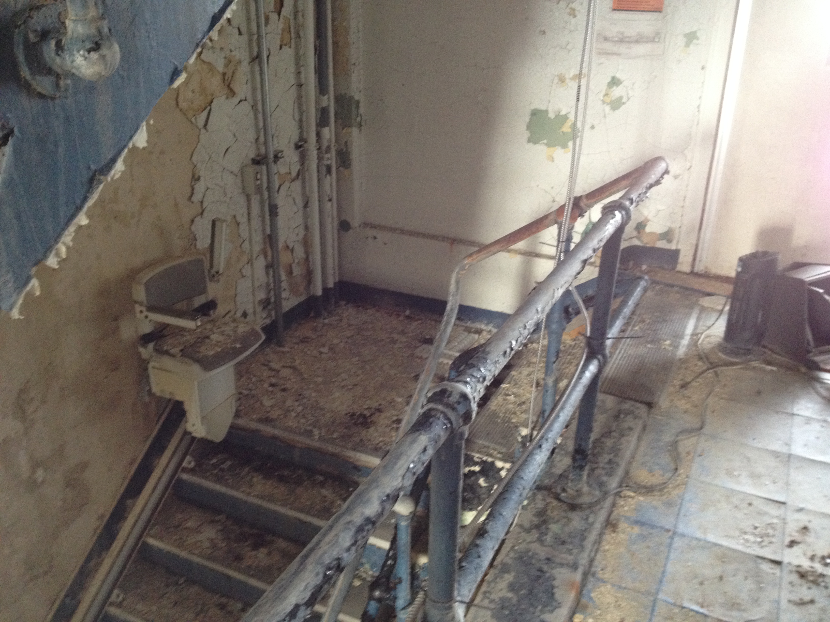
Stair lift – how do you get up the last 3 steps?
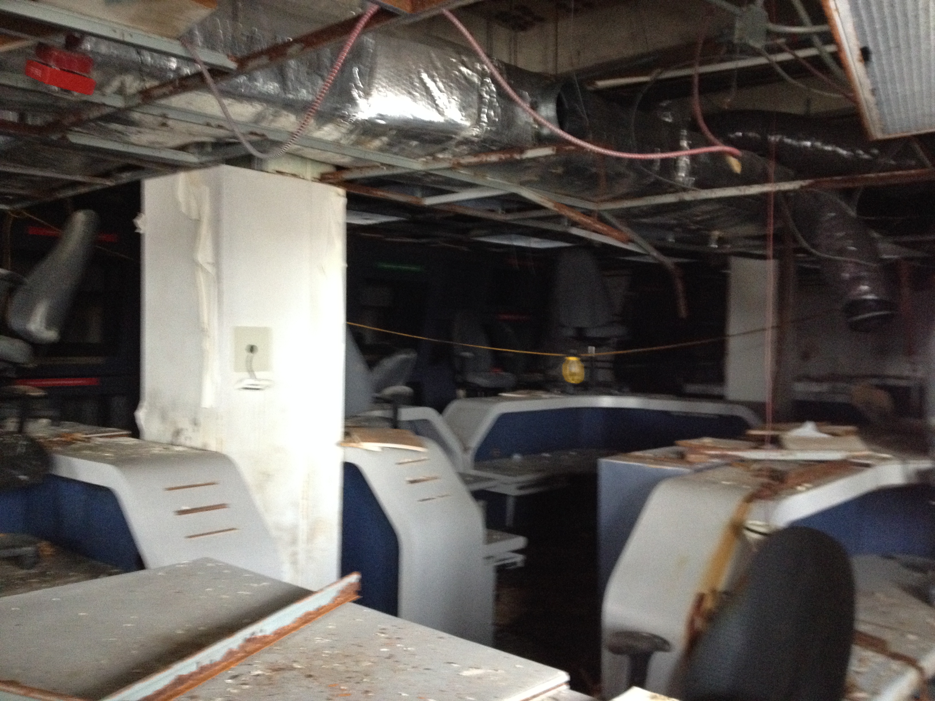
The Starship Enterprise Office that used to be Top Secret
As you can see all the HVAC will come out and be replaced! There are a few more weird designs but alas my camera lasted 11 shots at -8. The current budget is for $20 million to do the revamp complete. However the current estimate is $18 million to carry out the demolition alone which includes clearing out the debris and old office equipment. If this had been done at the time in 2006 instead that would have saved a packet. Now a specialist contractor is needed in full 4 Romeo to clear the building because of the biological (and asbestos) hazard. This project is likely to get paused whilst the budget is reviewed.
Two smaller projects are coming my way potentially. One is a new hangar at Ft Drum in up state New York. Based on a current design it will be my first chance on my own to design the HVAC. The second is a small Visitor Control Centre office block of about 5000 square feet which also requires HVAC. I have also been asked to go to West Point next week to look at a barrack block HVAC design. It is to have a new heating/cooling system which consists of underfloor heating in the winter which is then switched to a chilled roof arrangement in the summer. The Department for Public Works is the customer but is concerned that the set up will lead to condensation and mould growth even though it is ventilated. I will be going with the section chief as a technical expert. Best do some reading up!
And in other news…..
The cold weather is set to continue and the deep south is now in chaos after 3 inches of snow fell because they don’t ever get snow and had no ploughs! The Superbowl is this weekend but no Ravens this time as they actually got dropped from the wild card slot after a terrible end to the season. And the gun debate continues after a shooting in a Mall 30 minutes away. Luckily I have a thesis to distract me.
