Archive
An alternative view of the South Bank Tower from Tower Crane 1

Metalic insulation in a HV Switch gear room….thoughts?
John,
I thought this might interest you, how do you earth metallic covered insulation in an HV switch gear room? 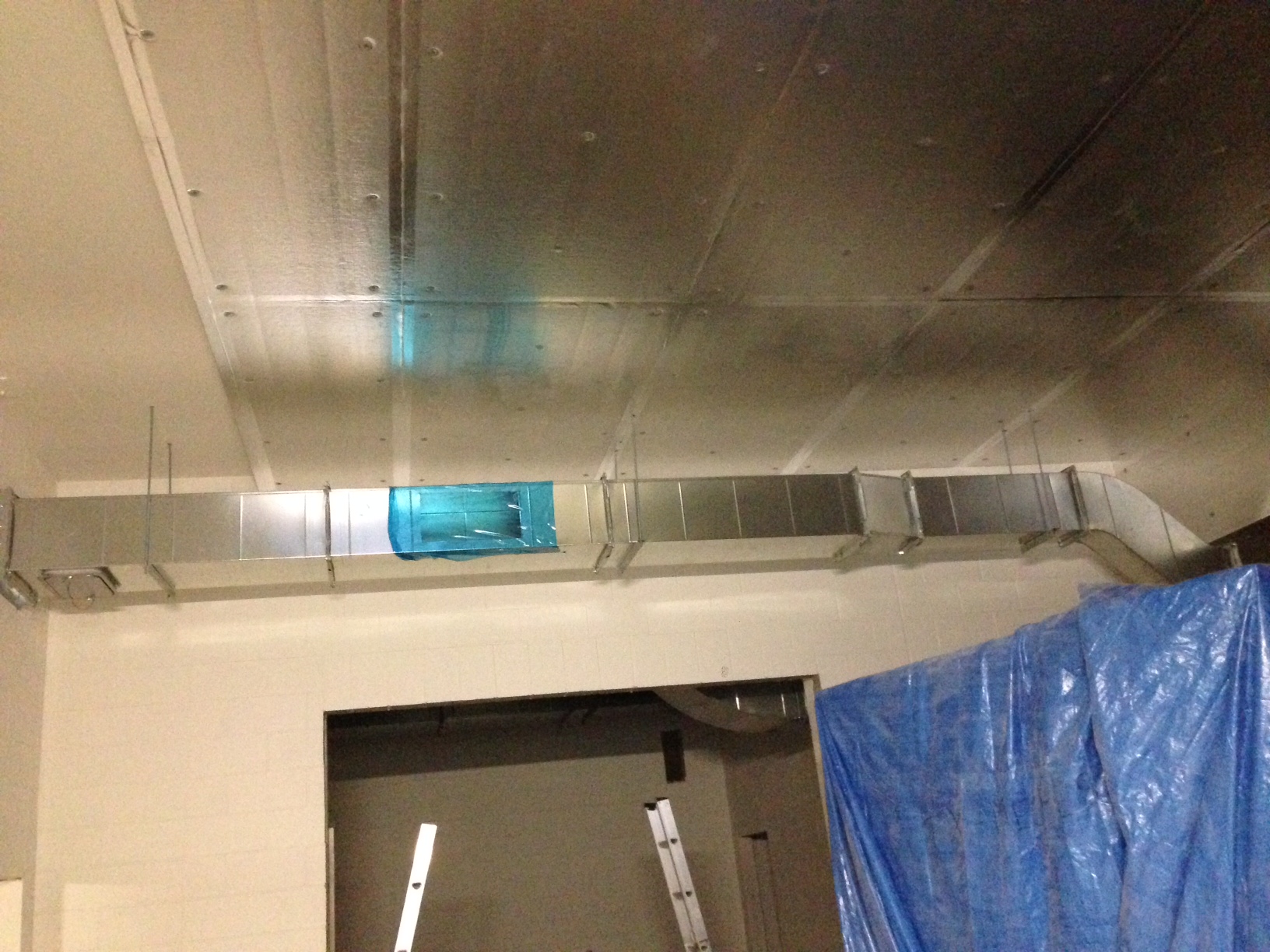
Aberdeen and Helicopter Stuff
I find myself starting the sixth week of work at BP and wondering where the time has gone. I can confirm that other than 2 weeks in Portugal skydiving that life has been rather sedentary.
I have been given to the programme area lead for ETAP (Eastern Trough Area Project) in the absence of any real plan. Thus far I am reading into two projects that will fall in my lap when they get handed off by the project engineer working on the first two stages of the project delivery process (Appraise and Select). I will then be responsible for the final two steps (Define and Execute).
Training
All I can say is that Chris did warn us about H&S in the industry. He wasn’t wrong, but what he didn’t prepare me for was the minimum industry training standard. Having been lulled into a false sense of security during the 3 day basic offshore safety induction and emergency training (BOSIET), which involved as much time in the heated swimming pool (not very representative of the north sea) as it did in the classroom, Nick and I were completely felled by the 2 day MIST. Essentially two days of unusually cruel torture by way of PowerPoint and a depressed American instructor!
But at least I can now go offshore.
PROJECTS
Mungo Rescue and Fire Fighting Services (RFFS)
Mungo is a normally unattended installation (NUI) that provides the topside infrastructure for the water injection equipment to enable enhanced recovery. The hydrocarbon is then piped back from Mungo to the ETAP installation, some 40kms away.
In Sep 13 the CAA initiated a safety review of offshore public transport helicopter operations
in support of the exploitation of oil and gas (CAP 1145 for those interested). It identified that fire fighting best practice for NUI had not been implemented. Therefore, Mungo is now to be fitted with an automatically activated delivery system for fire fighting foam.
There are a number of options that would meet the requirement, however, the CAA preferred solution is the installation of a deck integrated fire fighting system (DIFFS). Imagine having a permanently installed sprinkler system to water your garden and you’ve got the general idea. (Youtube link : http://www.youtube.com/watch?v=yBeNBqsVuKo)
As ever there is a wee fly in the ointment. BP’s Engineering Technical P (ETS) don’t allow for pop-up fire fighting systems. Cue the new guy working on a deviation (from the ETS).
Helideck Lighting
This task is also related to the CAA safety review. In relation to this task, the review identified that the pilots couldn’t see the helipad properly at night. So, we are going to light the helipads up like christmas trees.
Whereas the RFFS is only to be installed on Mungo, these lights will be installed on 7 installations starting with Miller, which is no longer operating but used as a hotel.
The project is towards the tail end of the Select phase (second phase of four). The trick will be getting a product out of Costain that will negate the need to do Appraise/Select for each installation. Installing the lighting on Miller is being seen as a trial and will act as a good rehearsal for the Wood Group PSN guys and girls.
Fortunately, this is not the first time it has been done there are however, a few technical limitations that have to be addressed / challenged.
Anyhow, the pictures below show what success will look like:

Helideck lighting – General

Helideck Light – Detail 1

Helideck Lights – Detail 2
And the kit we will probably use for that is:
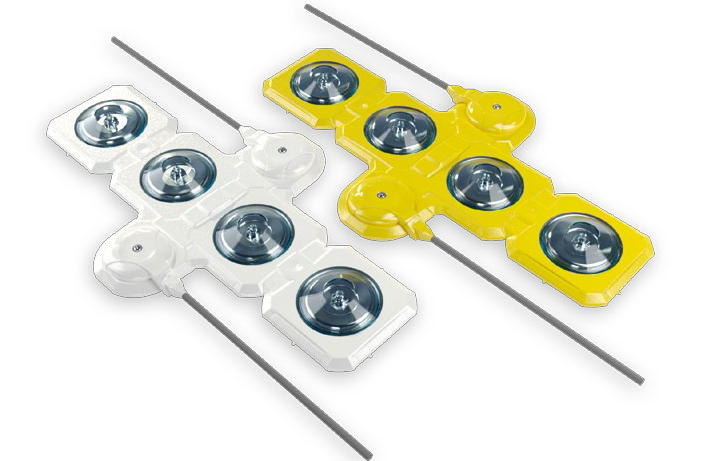
Orga Lights
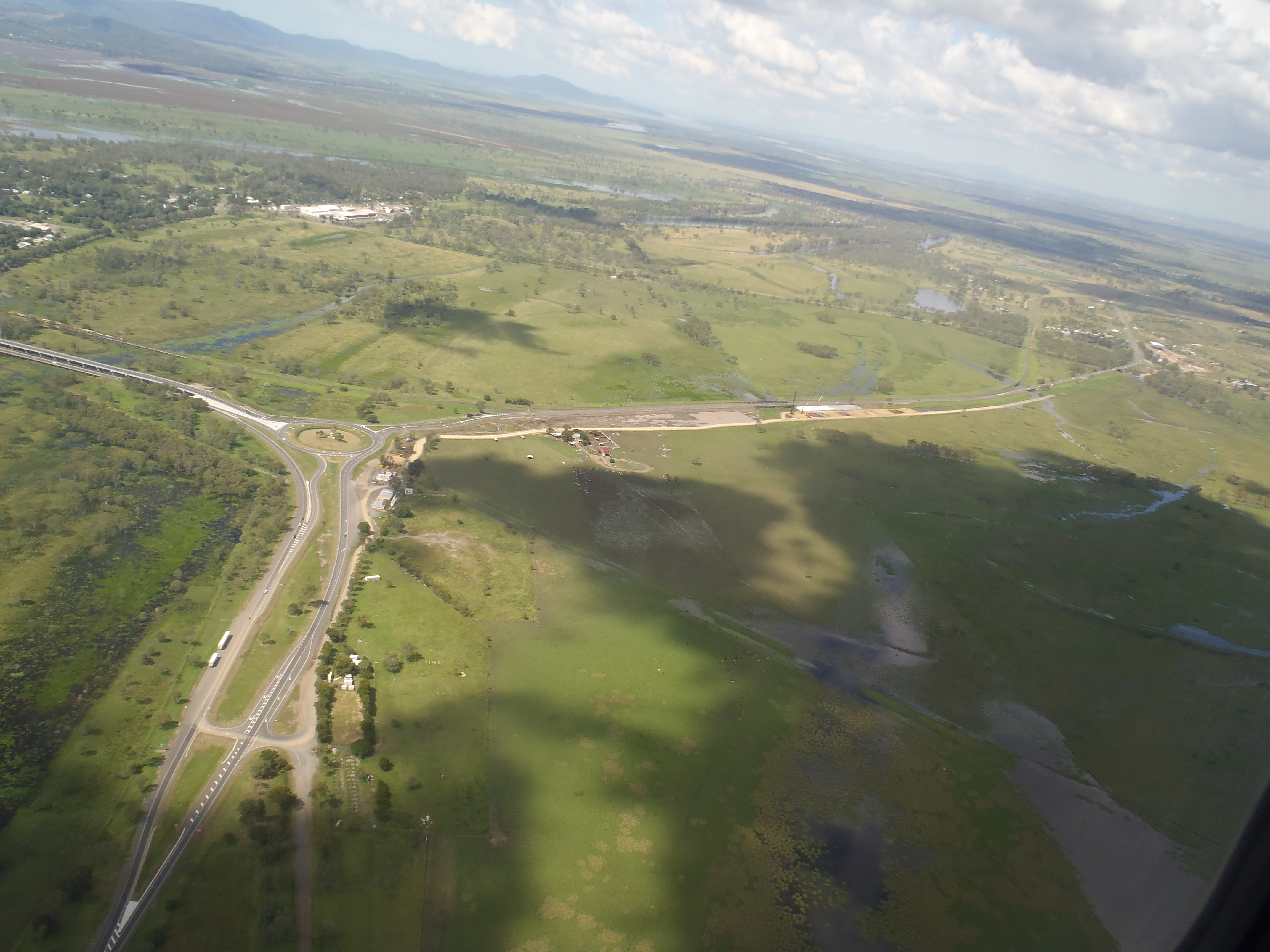
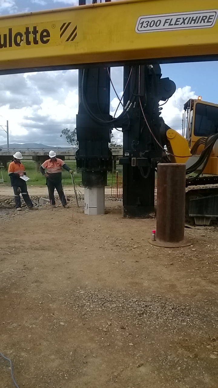
Finally a pile is in the ground!
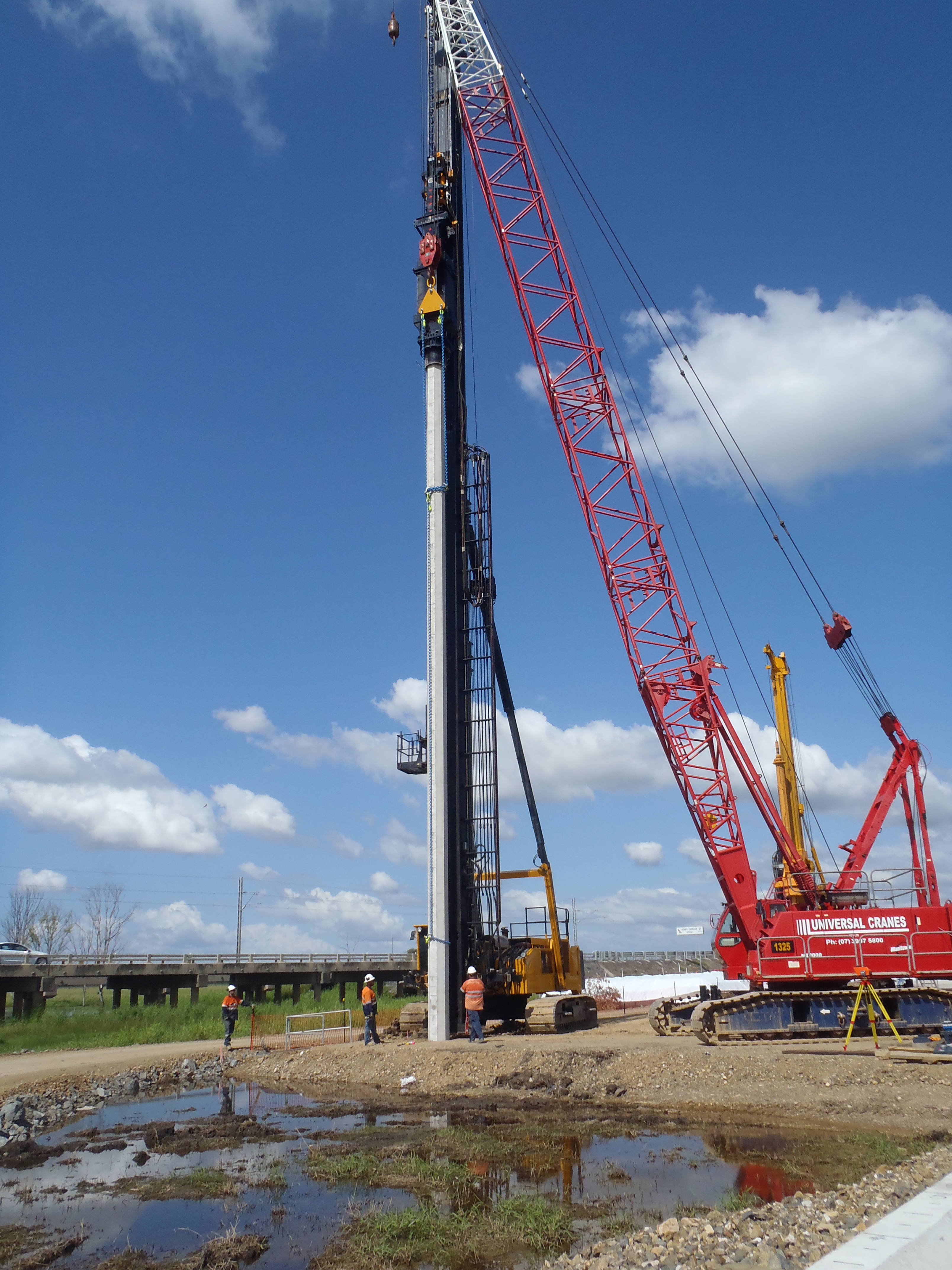
The piling subcontractor is finally on site and what I thought would be a nice easy period before the madness of concrete pours turned out to be anything but. First off the kit that they were confident would be up and running within half a day actually took closer to 2 days to set up. I have a feeling they were hoping to drag their feet enough so that Easter came and they would get a break without any piles having been driven. Thankfully their management gave them a reminder that they’re paid per metre of pile driven and so they started to move a little faster.
When it came to driving the first test pile the consultant engineers that are doing the monitoring set their gauges up and off we went. The pile was pitched without any problems and locked into the 26t hammer 23m in the air (26m pile with 3m prebore). The pile self weight along with the hammer weight caused it to sink about 4m in total. Driving started nice and easy and were steadily increasing the drop height when a hydraulic hose broke. This shouldn’t have been a problem to fix, except the subbie hadn’t completed the lift study for using the manbox hanging from the 110t service crane. This is despite having the info nearly a month in advance. The reason for giving so much notice is that John Holland have a classification system for all crane lifts. There is an easy to use table (it must be if I managed it) that rates the risk based on the weight, how close to the capacity of the crane you are and a few other factors such as multi-crane lifts and the conditions you are in. One thing that automatically goes into the critical category is any use of manboxes. This needs the lift study to be signed off by two lifting SMEs in Brisbane, the project H&S manager, the project manager and the area general manager in Brisbane. While this can frustrate some on site, the process is based on lessons learnt after crane incidents on various sites through John Hollands time in the industry. It has also frustrated the subbie somewhat as they had intended to use a 25t franna as the tailing crane when pitching the piles. Being a two crane lift there is an instant reduction in both cranes capacities of 20% (due to a small mis-movement from an operator possibly placing up to 80% of the load on one of the cranes). Now this means that the subbie needs to find a bigger crane, likely an 80t crawler crane. So the remainder of the afternoon was wasted as they tried to get a cherry picker onto site.
Thankfully the next day the cherry picker arrived, the hose was fixed and we were able to finish driving…or so I thought. The second monitoring requirement placed on us is that the piles need PDM (Pile Driving Monitoring) at the end of drive. This is a glorified laser level that sights onto a 3M sticker on the pile and records the temporary compression along with peak pile velocity. As we neared our design toe level we were still about 1000KN away from reaching our required set. We then went a metre past and still had a long way to go (only 60% of what we need). At this point I had to call a stop for a few reasons. 1) The gauges were about to disappear down the hole and they cost $5000 a pop. 2) We only have 3m overdrive allowance after the design toe height. 3) It was nearly 4pm on the Thursday before Easter. My thinking was that with the piling subbie away for 10 days this might allow the resistance to increase when we re-strike. Thankfully others thought this too, however there is still 40% of the capacity to find and if the soil profile is remotely right )which it might not be) then the toe is currently sitting in a band of sandy silt. I think this might become a contractual issue as the current plan is to fit a dolly to the pile to enable us to drive below the level of the rig. As soon as we hit 3m we hit issues with the length of rebar to be exposed that needs to tie into the pilecap, and the Dolly will only give us 1m more than the overdrive limit anyway. We’ll also need to fix the gauges to the dolly and try and figure out the losses from using it in the next 2 metres. I think I also need to spend a bit of time reading more into Johns notes on piling…
I’ve also had the first payment claim from the piling subbie in, mainly mobilisation costs for the first rig $85000 and the tiny bit of driving they’ve done. However I’m glad I checked as the standard method of measure in this contract states that length of pile driven is from the base of the pilecap. The piling subbie tried to claim from the top of our piling mat. That may only be 3m difference but at $90 per metre and with 1000 piles that’s $270000!
I also had a fairly long and important meeting with all concerned parties for the substructure sequence and methodology, and started to look at the cofferdams for piers 1 and 2, but I’ll save that for another time.
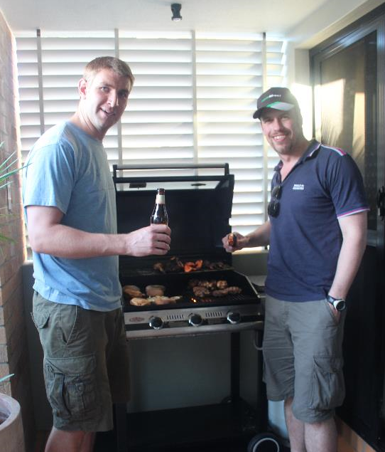
I went down to Brissy over the Easter weekend and stayed with Ben in his nice plush pad in New Farm. That gave a perfect excuse for a BBQ.
Phrases I’ve learnt:
“Bush Pig” – A woman who is not blessed with good looks, and resembles an unkempt wild pig
“Outan babi” – As above but in aboriginal (or so I’m led to believe)
My props are bigger than yours!
I have finally got my foot in my work boot and hobbled round site this week to find an exciting progression at the end of the basement. The diagonal props are in, the excavation completed, piles have been munched and the walers, bracing frames and thrust blocks are going in. To add to the excitement I keep hearing concerned conversations in the office between the basement section engineers about how the sheet piling has moved 20mm and is only allowed to move 5mm more and that a thrust block has been cast touching one of the piles and may need to be ripped out. All the talk about deflections, passive forces, failure and other key engineering terms attracted my attention and would make very interesting work if I wasn’t OIC drains, power, water, comms and road!

Back in the world of utilities, this week has been dominated by the incoming HV cables and Battersea Park Road Wall. 2 weeks ago it was decided that the electricity providers SSE were to bring the incoming ducts to the HV substation we had built. Last week they decided that they didn’t fancy burrowing under the brick wall and the Employers Agent T&T decided to send us a Request For Change at around 1800 Hrs the day before Good Friday. The wanted us to dig a trial hole to find the foundations of the 2m high antique wall, cat scan the area outside the wall on the footpath and then tunnel under the wall to meet the incoming service trench. I started looking at this on Tues and realised that their new proposition would remove manpower from our Network Rail Access Road work, involve getting permits to work on the footpath and then require a specialist to look into supporting the wall whilst tunnelling underneath which would also involve more TW designs, RAMS, etc. I spoke to our project director about it and he pulled out the big guns and sent it back saying it will take us 6 weeks (the power needs to be on by 1st May!). So this made my Client Utilities meeting extremely fun yesterday which I was left to chair on my own by Carillion. I went for the good old simple squaddie approach and suggested knocking the wall down as part of it was getting knocked down already and after much debate everyone decided that was probably the best plan. I then went out with the Buro Happold Design Engineer and we started to formulate a plan to give to the client. With things going seemingly well the installer from SSE threw a spanner in the works today saying that he was still working to the first revision of the drawing (we are on number 8!) and that he must bring the cables into site at 45 degrees not the 90 degrees. Cue another 45 minutes looking at the wall debating the best way to do it and not mess up the water incoming water supply or the yet to be built comms pits and ducting. I think we now have a very inefficient solution to knock down a part of the wall, bring the HV in and worry about the water and comms. Here is the wall of doom, HV was meant to come in on the left near the substation, then water in the centre and comms on the right. Now the HV is going to come in on the right, go straight over and next to the water (to make it nice and lukewarm for everyone no doubt) and comms TBC!

So why is getting things through a wall so difficult? Well my meeting uncovered a few issues; firstly a gap in scope where Buro Happlod have been contracted to design to the meter/substation/comms pits near the boundary wall and the incoming supplies were design by others. Secondly the client’s agent T&T have failed to get the utilities companies on board early enough to detail how and what needed to be done to get their kit into the site. Thirdly, Carillion and Buro Happold have been revising drawings but not as a request for change from the client which is why the utilities companies are 7 revisions behind. So despite their being no technical engineering issues I have been baffled by contractual language and experienced first hand the great arguments behind who will eventually be to blame/will pay for it when the power doesn’t go on in time!
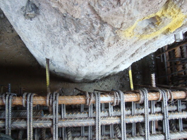
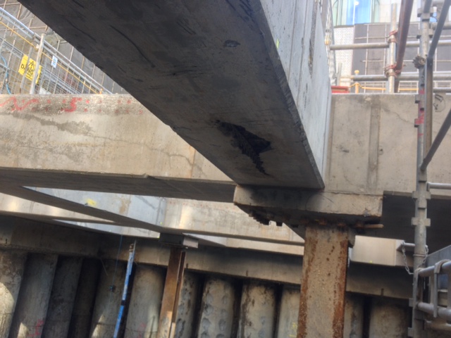
Concrete beam supported on 26mm bar……WHAT??
Having been working on the RC detailing drawings it wasn’t until I saw the shear quantity of steel and the congestion that I realised the magnitude of the work faced by the steel fixers. I noticed too that the interface between the pile s and the ring beam was by a poxey couple of 26mm bars. This has got me thinking that the next level of concrete is not held up by the connection between the piles and the ring beam.
In this case my thoughts are that the ring beam is in fact a whaler beam and the intermediate beams are acting as props. In this case the whaler beams are being loaded by the deformation of the piles and is acting like a compression ring. The load is then transferred into the beams axially loading them and putting them in to compression rather then acting as first thought purely in bending.
This theory is supported by the pile shape arrays (monitoring system) clearly showing that the piles are in bending and have in fact deformed by up to 6mm in some cases. In addition when looking at the distribution of the steel through the beams the steel is fairly evenly spaced. My thoughts are that the top and bottom steel is in fact designed to act in tension and compression in order that they can be axially loaded and resist buckling upwards or downwards. All comments, thoughts and pearls always welcome.
Honey Comb Concrete
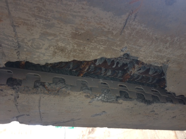
I have learnt today that this week that the term “Honey Combing” on a construction site has nothing to do with the thick sweet substance that Ryan pours on his porridge in the morning. Honey Combing is in fact the term given to poorly Lid concrete that results in voids in the finished surface of concrete.
Removing the form work during the excavation revealed a large area of steel rebar that the concrete had failed to cover. The cause was determined to be number of factors:
1. The operatives were instructed not to compact, vibrate and tamp the concrete excessively during the pour as the beam in question contained Geo Thermal pipes that were at risk of being damaged.
2. The concrete mix was not loose enough to allow it to flow around the steel to fill the void. In fact some of the slump test during the pour revelled stiffer then required concrete. The slump had been determined at an average diameter of 550mm and we had loads that varied between 650 and 400mm. The result was the expected dismissal of the concrete and a reshow for the concrete contractor it was a case of working the concrete a little harder. This was principally due to the fact that the concrete was already being pumped by the time a slump had been completed. Poor practice in my mind.
3. However ultimately I feel that pour steel fixing was the principal cause, although it is not a theory accepted among the entire site and principally not by the steel fixers. The pictures below clearly show that steel bars are packed too tightly and have prevented any concrete from passing between the bars to fill the void. The steel should in fact be lapped one bar on top of the other with the use of a cranked bar. In this case the bars were allowed to lie next to each other.
The upshot of all of this has been not and engineering problem more of a contractual problem. The making good of this void would seem fairly straight forward. The use of a fast setting cementitous mortar although it must reach the same strength or better then the surrounding concrete. My fag packet engineering behind why I feel this is a minor engineering issue is that the missing area of concrete is in fact only cover concrete and that the concrete within this region is concrete in tension with and in fact it is the steel that is carrying the load. Given that the beam is a rectangular section the area of concrete that could be removed would be half the depth of the concrete as all below the centroid would be in tension. The greater issue is that this section is typical in terms of steel across the site. A more worrying concern is that there may be more voids that can’t be seen. If a void is within the compressive section of the beam, typically here it would be the upper half of the beams, this would significantly reduce the load that could be carried across the beams. The quality control during the steel fixing was fairly stringent and while most of the team on site are confident that there would not be any further voids I looked into how one might determine if there were any further voids . The solution that I had come up with was the use of a ground penetrating radar. These appear to be fairly available for hire by many companies on line and are a very simple non invasive method of detection. Unfortunately the confidence of the team and the reluctance of the expense and delays to the programme means that we won’t be playing with any GPR systems and a non compliance report has been raised, once the making good has been completed the case will be closed.
New Children’s Hospital (NCH) Perth
Western Australia (WA) Wait Awhile!
The Project
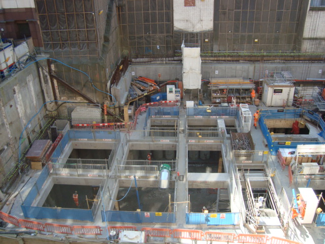
The New Children’s Hospital Perth has been in construction since Jan 2012 and is the largest structural project JHG has undertaken at A$1.2Bn. This is the same project as Nik West but I will be looking at the services not concrete, however since Nik left the project it has changed quite a lot. They are still pouring concrete for a project which is due to be finished next summer! However the services are at full steam ahead. I am lucky enough to spend most of my hours in the basement, which the only benefit is its slightly cooler! I work with one other guy and we are responsible for all the services within the basement, we have split the basement in two, I have responsibility for one half which is East and West block which can be seen in the following picture as the blue and red areas.
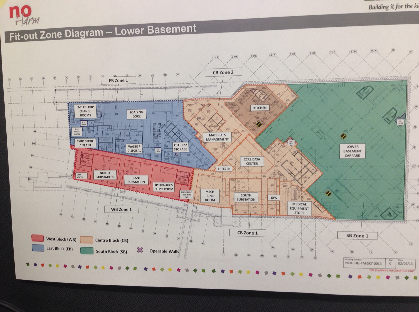
As you can seen from the pic it includes two substations, LV and HV, one large Hydraulics room including reverse osmosis, grey water treatment room, pneumatic tube room, fire pump room, multiple air handling rooms and all the services which connect them to say the least. My initial challenges are getting a full understanding of everything in each room therefore I can actually ensure everything is done correctly. My role is Services Coordinator which basically means everyone asks us everything about the services!!
So after my chat with my boss he said “Ollie the corridor of death is 6 weeks behind this is your challenge” the following pic is the corridor it will probably be a small focus of most of my blog’s as its the main artery of all the services. This is how it looks now:
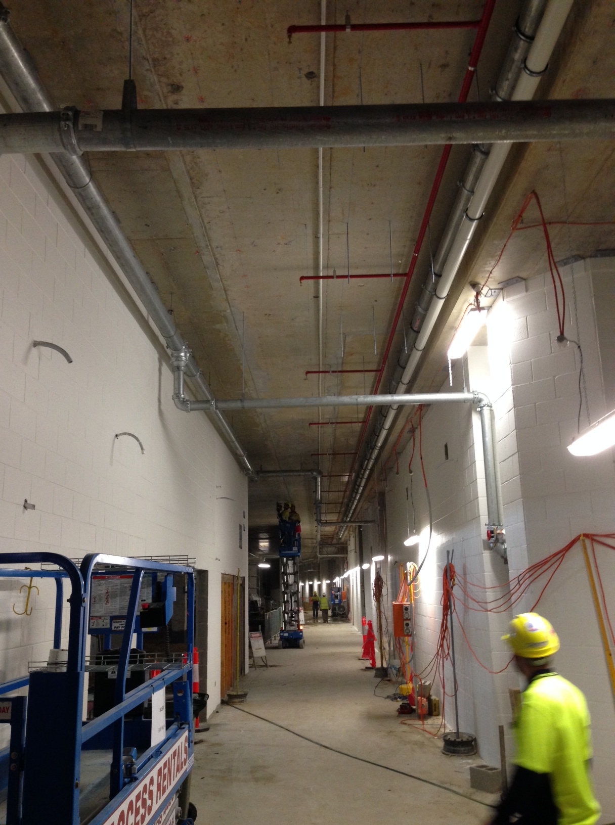
At present fairly sparse, with only wet fire (sprinkler system), fire main, Very Early Smoke Detection Alarm (VESDA) and some drainage. The hardest thing is the project is run using a BIM 3D model to ensure clash detection but not everyone one has bought into it, so we use the model but also have to do it by hand having discussion groups with the contractors and de-conflicting. I will go into more detail with the BIM modelling in the future. The following is a cross section of the corridor:
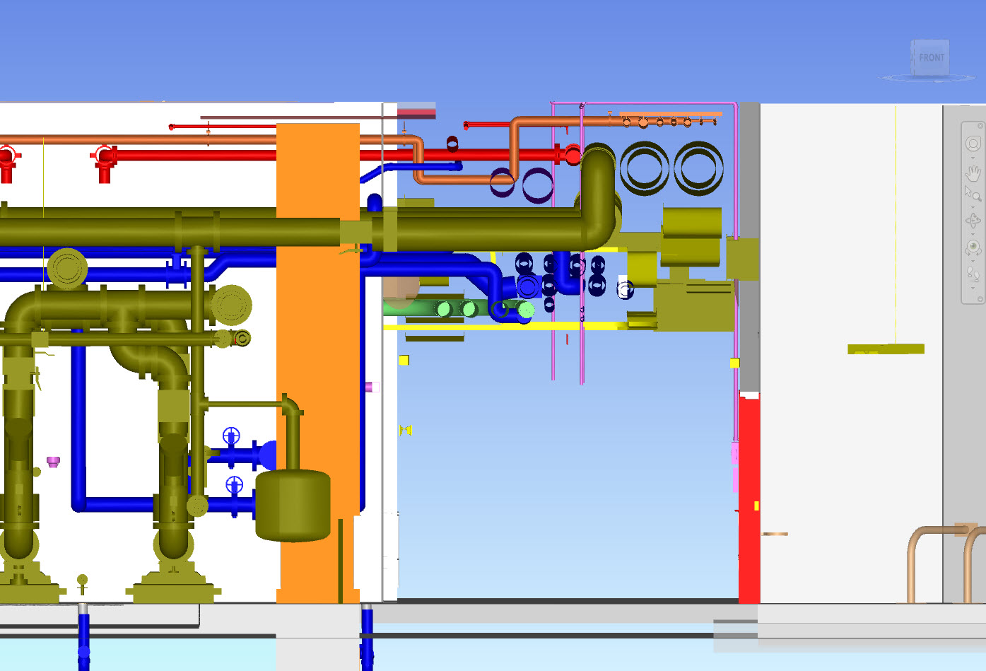
As you can see its busy and a lot to go in.
LIFE IN WA

Say no more…
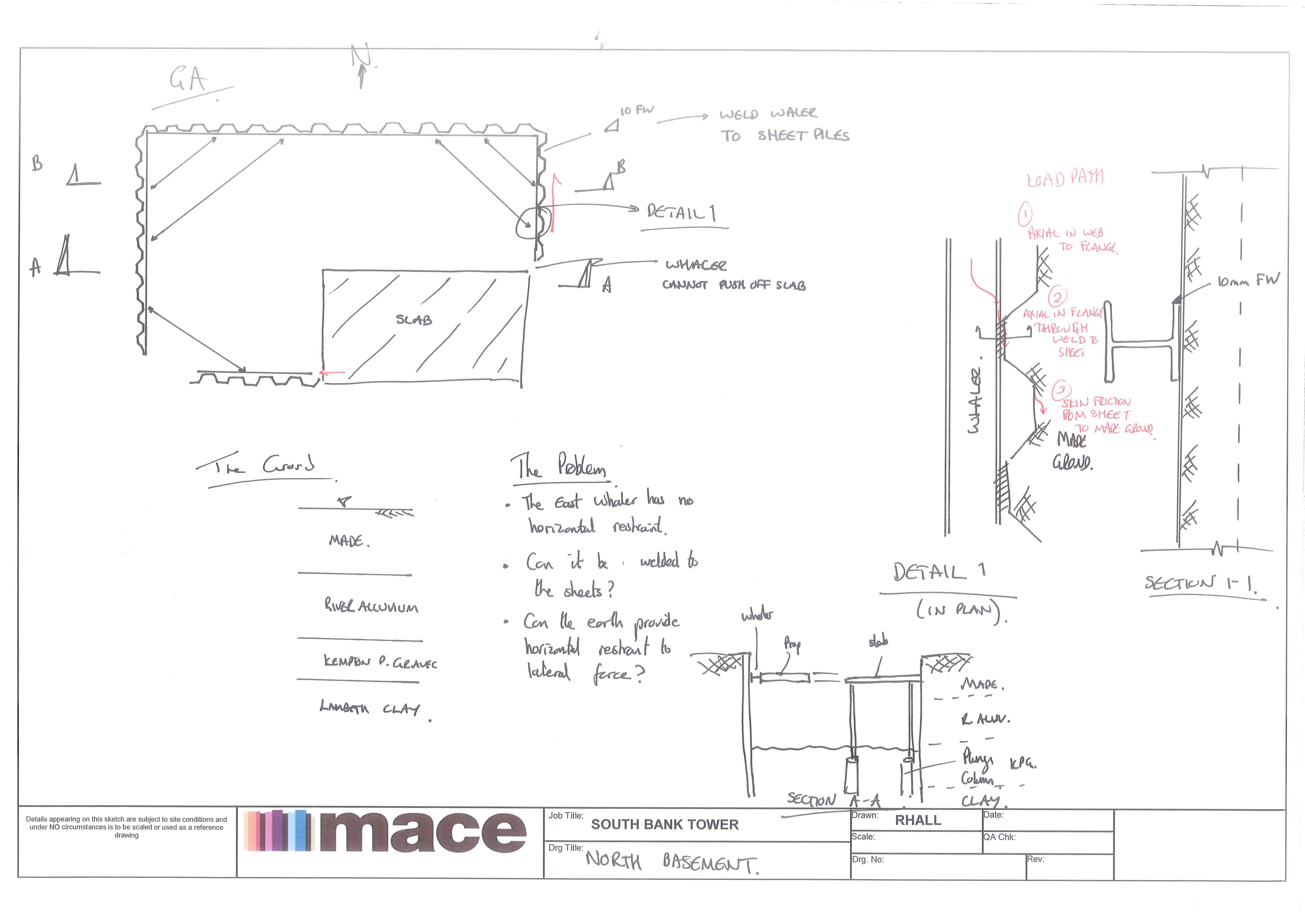
Shear loading a sheet pile wall
Here is a sketch our our North Basement Cofferdam. The deisgn by the Temp Works Engineer (Walsh Gp) assumed that the waling would be propped off of a slab (see sketch below). The only problem is that the waler cannot prop off the slab!
The temp work engineer proposed welding the waler to the sheets to ‘pacify’ Mace. Can you load a sheet pile wall with a shear load, ie using the sheet pile wall as a prop itself!!! I’ve yet to dig into the detail but is it even a starter!
A complicating factor is that the North Wall is a party wall and deflection must be kept below 12mm!
The piles in question are 11m long PU28-1SSP.
 T
T
Sappers in the Sydney
So with the definition of a time to Blog being the advent of a significant occurrence, and having conquered the mountain of post arrival in Australia administration (and having done as much sightseeing as I can bear for the time being) I thought it time to get involved.
Overview
I have been immersed in the (currently) 3 strong Services Delivery team for the University of Sydney Abercrombie Precinct Redevelopment project. The project is a $180 million Design and Construct of a new world class business School to house over 5000 students. Tendering was completed in early 2013 and construction started on site in Summer 2013. The Abercrombie Precinct redevelopment is the single largest increase in teaching space at the university since the 1960s and represents part of a redevelopment and expansion plan for the University that is expected to be worth > $1 billion over the next ten years. John Holland are keen to perform over the coming months in order to potentially win additional business and a slice of that $1billion
Consisting of 3 below ground floors and 6 above, Earthworks remain ongoing however the bulk of excavation of basement levels was complete in late, 2013 with construction originally scheduled for completion in Dec 14, however this is unlikely to be met owing to recent events which I will elaborate on later. In Nov 13 John Holland tendered for and won a $30 million variation to the contract to build a 3 story student accommodation block adjacent to the site. Demolition for works to start on the Student accommodation project began this week.
In terms of services the building includes
◾a 550-seat lecture theatre
◾three lecture theatres (300 seats each)
◾eight 100-seat case study rooms
◾40 seminar rooms of varying size
◾a learning hub
◾1500sqm of informal learning space
As a result AV plays a large part in the design, on top of the conventional Mechanical and Electrical Services (including AirCon) all designed to meet stringent 5 ‘Green Star’ Australian environmental standards.
Construction on a tight site has presented it’s own challenges. The site is hemmed in on three sides by university computer Sciences building (H69), privately funded university accommodation / college, and a public primary school. Access to the fourth side of the site is limited by the presence of a listed Blue Australian Gum Tree, which the planning office has said cannot be removed from site and is forming part of the architectural design of the building. Staged construction is taking place from one end of the site to the other and the Limitations on ingress and egress routes mean that careful planning must be undertaken on a daily basis. The below video highlights the phased construction of the facility, layout and access issues. .
![IMG_1595[1]](https://pewpetblog.com/wp-content/uploads/2014/04/img_15951.jpg)
A cramped site that is hemmed in on all sides makes for multiple trades working on top of each other.
![IMG_1596[1]](https://pewpetblog.com/wp-content/uploads/2014/04/img_15961.jpg)
Possibly the most expensive tree I have ever seen – An Australian Blue Gum worth $250000 to the client in LDs if it is damaged.
Design Philosophy
Until last week the construction of the business school was expected to be running approximately 3 weeks behind schedule. The design for the Business school has been subcontracted to a consultancy called Kannefinch, who are continuing to develop the design in conjunction with specialist subcontractors, over seen by John Holland engineers. This means that for the bulk of the three weeks I have been on Site, the Services manager and other Services Engineer have been based out of the design office in central Sydney. A holistic approach to design has been undertaken with the entire design (including Services) being modelled in BIM 360 from the outset (a first for the design team and contractors employed, if not John Holland as a whole) as opposed to as built drawings being used to design and manage the ongoing building life. This has presented significant challenges, not least the requirement for subcontractors to become conversant with the new software, but has allowed multiple advantages – The design can evolve while construction is underway, with designs for the higher levels of the building being undertaken with work underway on site, reducing overall design to construction time. Weekly clash detection meetings between the design team highlight areas that will cause issues, which are resolved on an ongoing basis. An example of this would be a significant conflict between the volume of air that is required to be moved by the Air conditioning system (against strict University Guidelines) verses the ceiling space that is available to house ductwork, which is governed by the usable space and limits on the building height. By having the entire design team attend clash detection meetings, including the structural engineers, design solutions could be achieved that included ‘notching of beams’ (highlighted well before the beams are poured and with the approval of the structural engineers)
As a result the remaining two members of the services team are continuing to be involved in design refinements, and are expected to move from the design office to the task site within the next week.
Tasks so far
My role so far has been as the Services Engineer on Site, replacing the previous Site services engineer who left the job last week, and whom up til now I have been conducting handover training with and attempting to extract as much information from as possible. With slab pours for the various floors ongoing my work so far has been focussed around quality assurance, designing and carrying out Inspection and Test Plans (ITPs) for services penetrations in slabs, and highlighting areas where the Formwork has been incorrect. I have also been involved with ground penetration permits and authorising permits to dig, looking for and testing for existing in ground services, as well as reviewing air conditioning designs for construction detail, allowing the designs to be manufactured and installed rather than the engineering physics of duct sizing (which incidentally has been conducted by the static regain method), and the practical applications of sequencing construction on site.
Aussie life.
It’s not bad. I think i’ll leave it at that, Brendan may have an aneurism if I say any more.
![IMG_1571[2]](https://pewpetblog.com/wp-content/uploads/2014/04/img_15712.jpg)
That’s the view from My flat in Neutral Bay , so New years is sorted, and I cycle to work across SHB everyday, KY has been to stay and I’m even beginning to get the rules of Aussie rules….
That should about do it for my first blog. Watch out for the sequel, coming soon – “When Good Pours go Bad’
