Concrete Bicuits and Big Cheeses
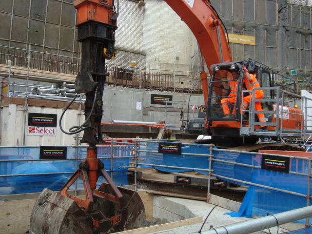
Monday began with the breaking ground ceremony with a veritable smorgasbord of big cheeses in attendance all vying to be in the seat of the clamshell excavator for the corporate picture. When instructed to put up “loads of signs” on the site the lads took this to the extreme and I invite you to count the number of Lain O’Rourke signs in the picture.
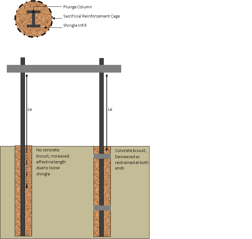
I feel it is probably an appropriate time to explain the construction method and some issues that I/we will face with the construction. The Blomfield box is a top down build. In this case a contiguous pile wall has been augured and poured to a depth of 70ish metres. The first main slab was poured two weeks ago and we are now excavating beneath the slab. Each subsequent slab and excavation will be complete in the same sequence; excavate, pour working surface, fabricate reinforcement cages, pour concrete slab and beams and then excavate through and beneath to the next level. No columns or walls will be constructed until the final level is completed at the 71SSL. All walls and columns will then be constructed working backwards towards the surface. As a result the slab and beams are required to span a gap of 25-30m in places. With no columns or walls beneath the beams the entire slab will be in tension throughout the duration of the excavation. In order to reduce the span steel plunge columns were cast into a steel cage and then backed filled with shingle. The 40m plunge columns act as intermediate supports for the slab during the excavation and then will be cast into concrete when the remaining walls and columns are constructed. During the excavation the steel plunge columns are to be exposed and are then at risk of becoming slender columns and buckling. In order to overcome this two mitigation methods have been applied firstly the max load on the slab has been limited to 5kPa and secondly the steel columns have had concrete biscuits cast in to reduce their effective length during excavation.
The drawing below shows each level of excavation, approximately 6-7m and the columns once exposed between levels and prior to the construction of the slab are considered to be slender columns if not restrained. In order to overcome the problem that over excavation and to ensure the column is restrained concrete biscuits 1200mm deep were cast around the plunge column thus reducing the effective length and making the columns stocky. Problem solved.

Well it’s certainly getting interesting
A few queries:
You describe the box as formed by 70m or so deep contiguous piled wall – very unusual to form such a wall to this depth- I’d have guessed that it was a diagphragm construction?
A bit confused with the assertion that no columns will be formed on the way down
The plunge column technique usually means that the columns are plunged into an auger bored hole – filled wilth concrete; the excavation proceeds form the surface exposing the column which is then used:
a) as intermediate suport to beams supporting the slab cast above;
b) as starting columns for any superstructure to proceed contemporaneously upward
I guess a column with a cage could be introoduced into the bore and the remaining void filled with gravel- excavation would reveal the steel. Never heard of this and it would be a bastard job to det in the ‘doughnuts’
Equally I cannot quite get the doughnuts. The amount of strain to bring the gravel around the column to passive ( and hence rertained) is relatively low – particularly if the gravel were vibro-compacted around the column.
I would have though that the column section is north of 356H and likley to remain at full axial strenght unless the temporary design end moments were high (it could be that the temporary axial actions were very high – but I doubt it)
The 25-30 metre spans – can’t be. You say that the slab works in tension in the temporary condition. This would imply catenary. This is a state is often invoked as a temporary state for robustness during collapse – but the implication is that the strains are high to place the slab in catenary and since it is a collapse state serviceability deformatins do not have to be considered ( in other words the asumption is that the slab yawns and hangs there – for long enough to permit escape.
S0 …..as I say….interesting
COnfused of Chatham
understand the piece about beams being too long therefore reducedin length by use of intermediate supports in the form of plunge columns. Would like to see diagram showing location in plan view. How do these columns fix into the slab – what happens to punching shear? Also not sure how you proceed from casting the second slab onwards. Can you expand this to the full construction sequence to satisfy my ignorant curiosity?
Steve
Excellent CPR stuff – provided that you are completely OK with what is happening where
Kind Regards
Neil