Home
> Uncategorized > Shear loading a sheet pile wall
Shear loading a sheet pile wall
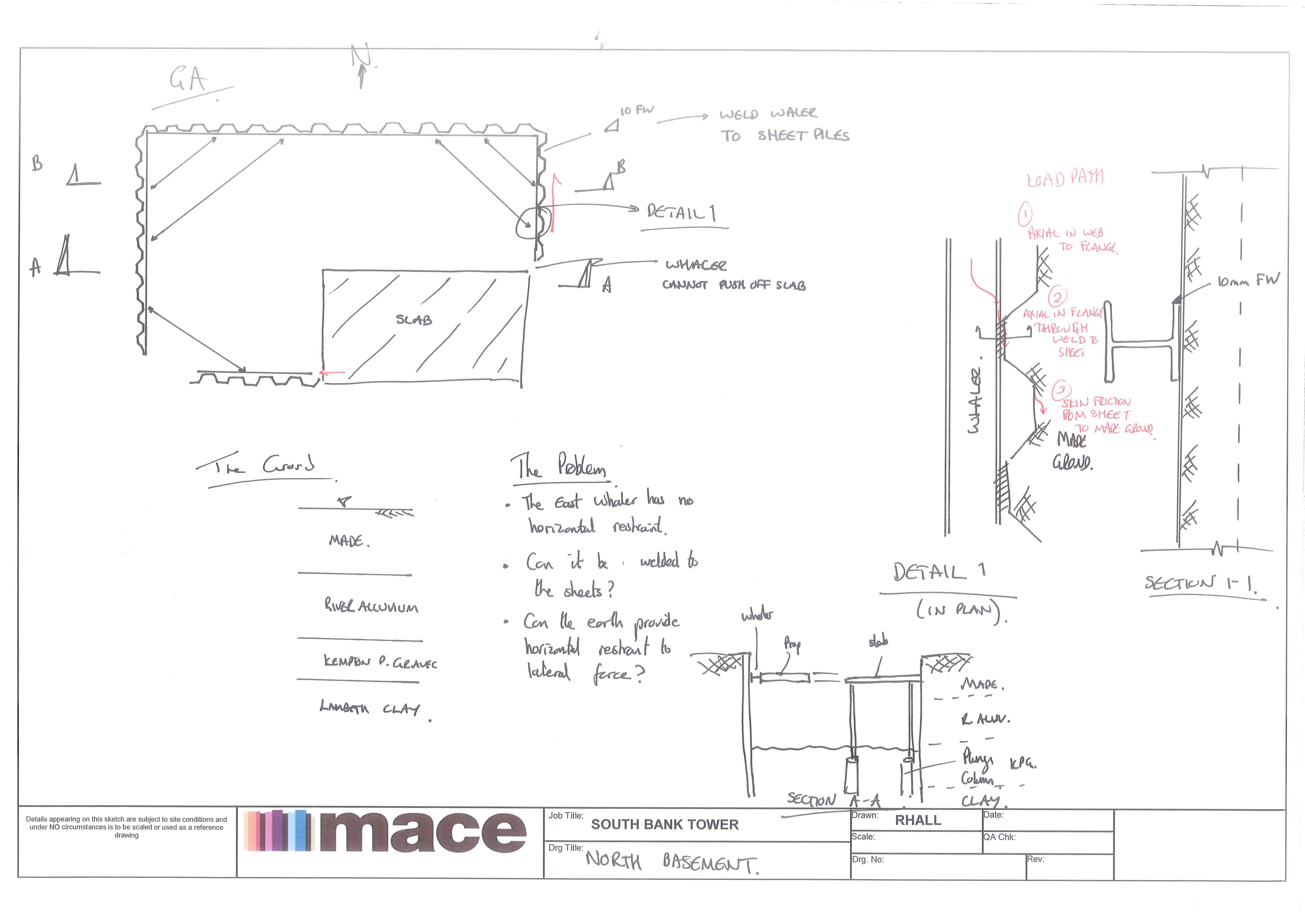
Here is a sketch our our North Basement Cofferdam. The deisgn by the Temp Works Engineer (Walsh Gp) assumed that the waling would be propped off of a slab (see sketch below). The only problem is that the waler cannot prop off the slab!
The temp work engineer proposed welding the waler to the sheets to ‘pacify’ Mace. Can you load a sheet pile wall with a shear load, ie using the sheet pile wall as a prop itself!!! I’ve yet to dig into the detail but is it even a starter!
A complicating factor is that the North Wall is a party wall and deflection must be kept below 12mm!
The piles in question are 11m long PU28-1SSP.
 T
T
Categories: Uncategorized
Cofferdams, SBT, Sheet piles

Well I think I see the problem; the raking struts in the NE corner land on the waling to the eastern sheet pile wall. The southern end of this waling was to be propped on the concrete slab but is now without end support and the temp works designer is proposing wleding this wale to the N-S running Eastern sheet pile wall such that the N-S sheat between wall and rear soil supports the N-S component of the waling compression. ( in other words, can the force represented by the red arrow you indicate be developed by the pile wall interacting with the soil it is embedded into?)
IT would imply a shear between the wall the the soil running N-S There is always a omplementary shear to this horizontal one- equal to it. I guess equilibriums would be
Can sufficient lateral shear resistance be developed ( wall to soil)
What effect does the complementary shear have on the soil drag down behind the E wall?
I was thinking I could use the soil wall friction angle (δ, delta). Taking a δ, ranging from φ/2 to 2φ/3, I could use this to get a Ka. Use this Ka and multiply it by the effective stress and then by the area of the sheet/soil interface to get a Force!
As for the compilentary shear! I’m thinking the shear box test where the shear implies an expansion (dilation!). This dilation would then generate greater prop forces on the cofferdam.
My main issue with this is whole affair is that a shear requires a movement and we don’t want movement!!!
Yes that would be a sound approach- for a number of reasons:
1 Although the pile section is rentrant no real passive reistance can be developed in the direction required
2 Since the piles are almost certainly vibro driven into place they will be in intimate contact with the soil
As for strain…the shear strain required to mobilise shear reisitance …well again think of the strain displacement squiggles…if the soil is dense of citical voids ratio…then this is low…so was the soil dense or loose and what did the pile driving do to improve this?..one record would have been the amount of work done in installing the piles…but using a vibro head off of a crawler arm …this is seldonm formally measured…the rig operator usually know though
I spent a day with a sheet piling outfit last week….nice guys, but they were giving clients deformation esitmates from software…and not to put too fine a point on it …..didn’t really have a clue why different approachs to limit state design were ‘estimating’ difference deformations….and pointing to the stiffest response and ….using that…FIne, in the respect that they were using experience but ….on discussion it tuned out that at least one client was suing for ‘over-deformation’…..well well well
Providing deformation limits of 12mm is a nonsense in geotechnical engineering…anyone with half an education would know that. But commerical pressures forces such cack. Saying something like- probably less than 20mm might…just might…be sensible
If limits around 10mm are absolutely necessary ( and I wouldn’t know why) then the observational method would have to be in operation
ON your dilation point…yep I sort of understand…remember that ( and this was the mis understanding with my piling friends last week) the stresses the these walls are designed for in the limit state are way below the service state ( remember?. The greater the limit of movement the higher the design stress behind the wall…..if you then design the wall response as a beam supporitng a varying soil load….er….the higher the implied deformation ….. but that implies a relaxation in the stress driving the deforemtion…well doesn’t it?
IN short to model wall dispalcement …at all … you need a soil structure interaction piece of software and an estimate of …wait for it…soil stress….run for your lives!
Your case is …even more complecx BUT again for a dense soil the shear strain to develop peak shear resistance is …..Looooow