Archive
Bahrain
Hi all!
Good luck to all those preparing for CEng and E +M interviews…
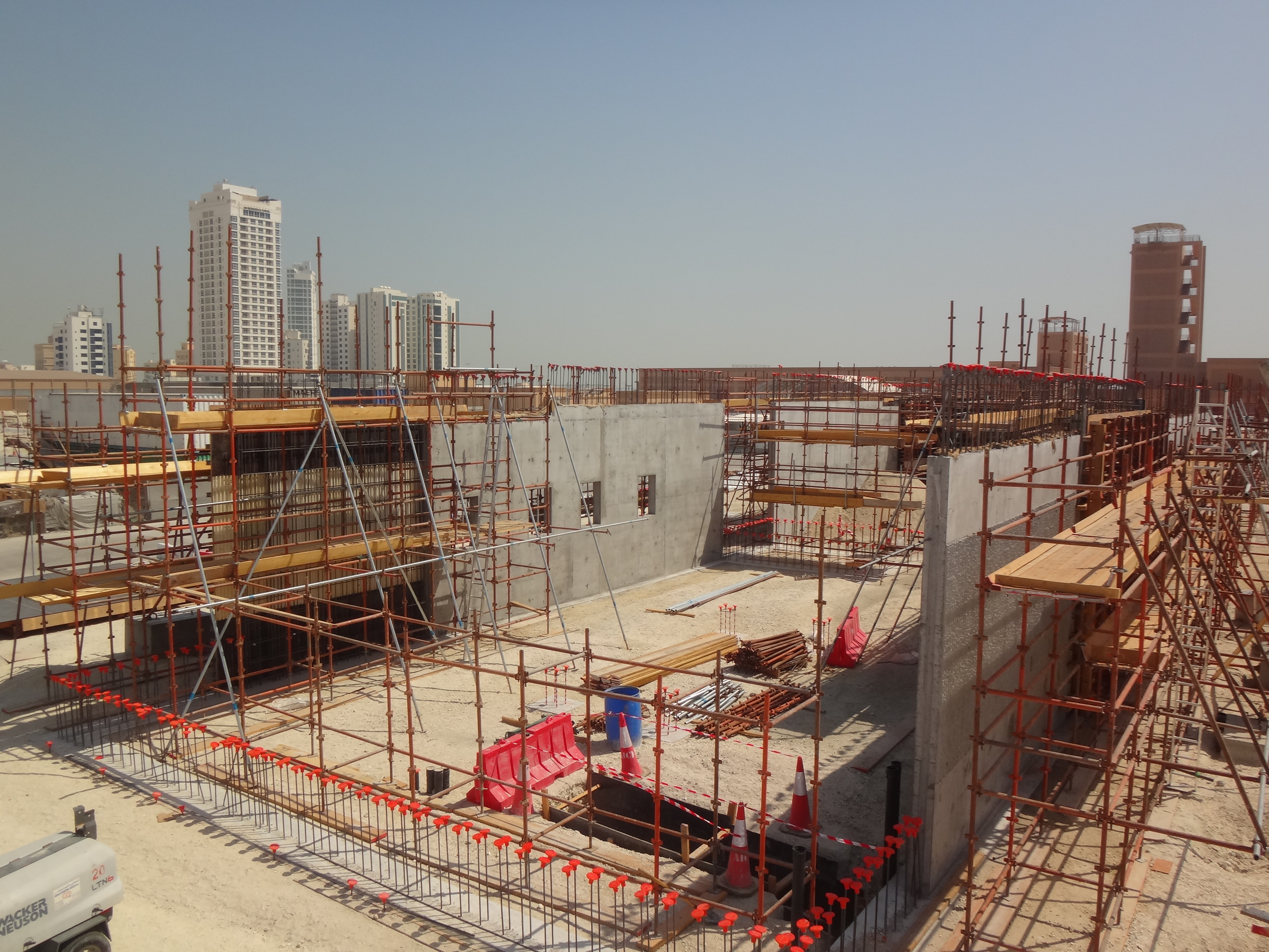
I’ve posted a few photos of Bahrain.
WWW.ROSELLIOTT.WORDPRESS.COM
I’m being replaced in November – one of you may find yourself here…no…really!
RE
Not playing nice….
As part of the Liverpool street station the northern wall of the Blomfield box which will create the interface between the Blomfield superstructure and the London Underground (LU) Circle and District line was due to be an RC pour insitu wall with aluminium rain screen cladding. Well not any more. Following extensive campaigning by Laing O’Rourke since 2012 to produce this wall in precast and countless rejections Crossrail finally agreed to completing the wall in precast concrete, however this has left Laing O’Rourke only 4 weeks in which to turn the designs around in time for the next design review which is critical to the 3D modelling.
The Issue.
Build-ability. The original wall and cladding were due to form the interface between the LU and the permanent structure of the Blomfield Vent Relief Shaft. Between the LU and the construction site is a temporary heavy duty hording. The space between the hording and the back of the RC wall was only 350-400mm, which given the size of the form work sections required to pour it would prove difficult to fix in place and even harder to then remove.
H&S. The only means to remove the formwork would be to remove the heavy duty hording. This presented a considerable H&S concern due to working next to live track.
Commercial. Working track side could only be achieved during track closure (engineering hours, 0200-0500). Working during engineering hours would present considerable time constraints and incur additional cost.
The Proposal.
Replace the RC wall with a precast twin wall. Precast twin wall could be constructed off site and the lowered into place reducing construction time and also negating the need to work track side (when constructing the wall). The overall cost for the wall could be reduced with reduced working hours, reduced transport cost of only transporting the twin wall rather than rebar deliveries and concrete pouring deliveries.
The Actual Project managers instruction
The RC wall and cladding are both to be replaced by architectural grade single skin precast wall. Of which LOR are to take design responsibility (actual instruction a little more indetail)
Having been given the responsibility to deliver the precast facade as it is now known as it is doing the job and the cladding but is not structural I have become embroiled in the dirty world of commercial and design responsibility. While i have very little engineering input with respect to design the facade for loading but I have all the responsibility of coordinating the effort of the architects and engineers from Crossrail, LOR and Arup. Lessons learnt to date.
Open to Interpretation. The PMI was written in such a way that Crossrail believe that it allows us the scope to think outside of the box and come up with our own design. As LOR do not have in house architects or detailed design teams we have had to employee Arup to complete architect designs while LOR would use its subsidiary company ‘Expanded’ to complete structural designs of the precast facade panels. The vagueness of the PMI has resulted in each stakeholders understanding of what is required being different and therefore what the facade is suppose to achieve what loads if any it is to carry and how it will look.
Design responsibility. The vagueness of the PMI has also resulted in endless wrangling over who owns what design responsibility. The architects claiming that they cant design the facade overall appearance unless they know how it is to be constructed fixed and loads transferred to the superstructure and the engineers from Explore claim that until they know how the facade is to interface with the superstructure they can’t design the internal rebar and how the loads are to be carried. At present there is no clause in any contract apportioning design responsibility either in the Crossrail contract, the PMI or the LOR to Arup subcontract. Until this is assigned then designs will not progress.
Ground Truth. The discussions were further stalled by the realisation that the as built drawings that were being worked to by the architects from Arup and engineers from Explore were in fact wrong. This was only picked up during a meeting when I noticed that the drawings that were being used and assumed did not match with my knowledge of ground truth. Lesson here always check that as built actually reflect what has been built and not what people want others to believe has been built to avoid penalties.
Commercial Knowledge. As John has often stated do not assume that others know what they are taking about. This goes for contracts as much as engineering principles. Members from the Crossrail team had been stating a claim that I found out later to be false; Cross rail claimed that Laing O’Rourke were responsible for removing the heavy duty hording. This turned out to not be in the scope of works and is important as it removes the problem of removing a concrete plinth that would once expose a section of the superstructure not covered by cladding. Not the end of the world structurally but for Crossrail and the architects a disaster. As we do not need to remove it the problem of extending the facade beyond the concrete plinth goes away.
Relationships RA and foresight. There appears to be an approach in the industry that its not my problem i don’t need to consider it. The original proposal state a twin wall to replace only the RC wall on H&S grounds and build-ability grounds. When the PMI was issued complaints were made that it was not inline with the proposal, however the engineers and construction managers (who are the guardians of RAs) had failed to note that simply replacing the RC wall did not remove the risk posed to a further sub contractor who would then be required to install the aluminium rains screen cladding. This should have been picked up at the design stage but then again by LOR. If the risk is too great for your own work force why pass on the risk to a further organisation, why not eliminate the risk for all. The replacement of the RC wall and aluminium rain screen with the single precast facade does just this.
Conclusion
The whole contractor, designer and client relationship is crucial and I am not convinced that many in the industry understand that. A client and their designers must make use of ground truths and experience from the coal face as much as the coalface must understand the designers and clients intent. When designs change and there is an opportunity to pass the buck to someone else people will take it, and architect and engineers just aren’t capable of playing nice.
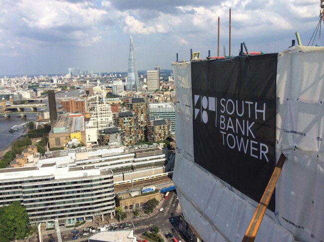
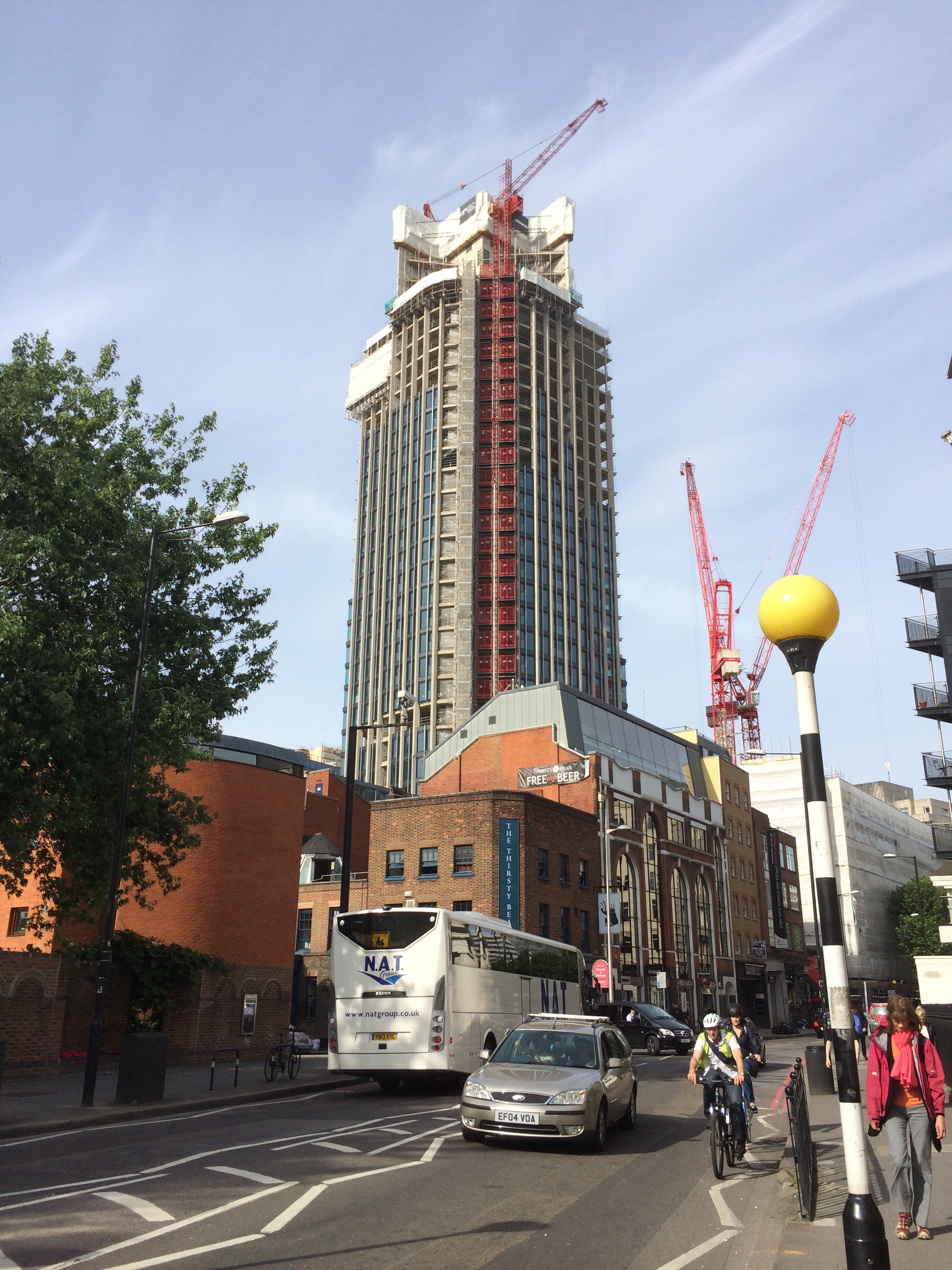
Half way to the top
The tower extension is starting to finally take shape. After a few somewhat stressful weeks getting our sub-contractors temporary works together the slipform finally launched from level 30 of the old tower.
The slipform is somewhat like oil tanker destined to have a near miss with some rocks and then be broken up! Once it is going there is no stopping it easily! And at the end of it journey it becomes redundant and is ripped to bits and cast aside!
The walls of the new tower core are only 200mm thick. This has been causing issues with fitting everything into the wall. Cover, small embed plates, climbing tubes, horizontal and vertical rebar makes for a congested beam. This has meant that whenever the slipform reached a floor level the rig was stopped for two days in order to allow all the reinforcement to be fitted. This pause also allowed us to fit bracing to the wing walls that act as sails in the wind.

The narrow walls also makes it very difficult to stop embed plates from dragging up inside the slip as it is jacked up. The embedment plates allow the exterior steel beams to be connected, with a welded fin plate, back to the core. If anyone finds themselves at a consultancy designing slipform makes the walls thickets and use 16mm vertical rebar.
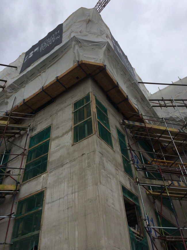
Now I mentioned the near collision with the rocks and this ship. Well we, Mace, never really thought PC Harrington would deliver this tower core without fault. So surprise surprise on Friday when they informed us that two of the six corner MacAlloy embed plate pockets were in the wrong. This week we have been brainstorming to rectify this problem since there is no longer any free space to introduce the 1.5m x 2.5m embed plate into the core. See corner below.
The cost to rectify this sits firmly with PC Harrington. It could, worse case, require significant temporary works to remove 1m of concrete above void such that we can get vertical rebar continuity across the embed. Best case, we can locally break out the wall to get the embed in, but the the vertical rebar won’t tie, which I’m guessing the structural engineers won’t be happy with.
The slipform is now at the 35th SSL level which is where the four outrigger (wing) walls terminate. Therefore the rig has to be temporarily dismantled in order to allow it to continue to level 42.
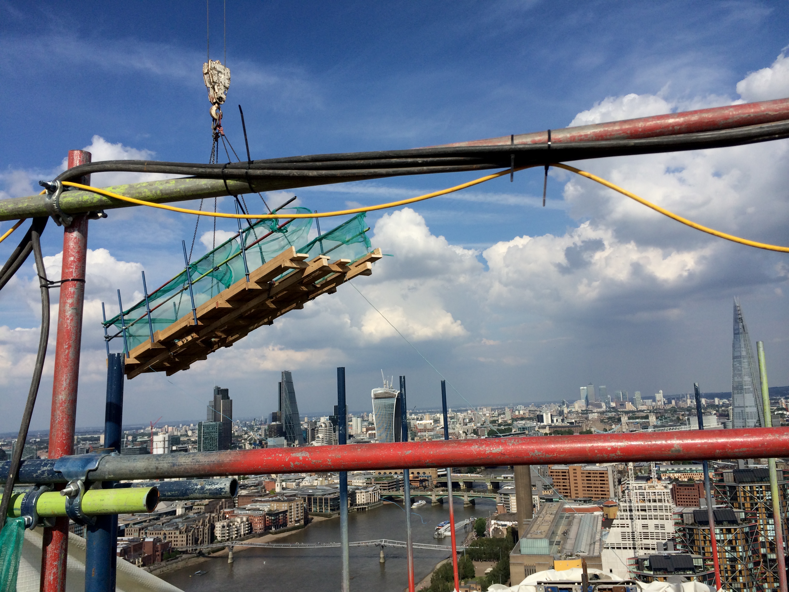
Here is a picture of the top deck being lifted off. Tomorrow we will be lifting off the working deck and hanging deck together. It is a pretty precious operation since most of the lateral restraint of the slipform has to be cut to lift it down to ground.
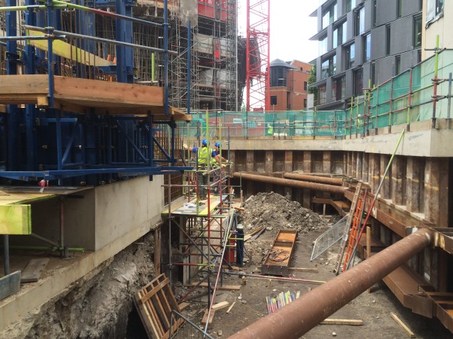
Elsewhere in the project our North Basement excavation is progressing (very slowly). The second waler is now being installed. This retaining wall is along a party wall and deflections must be limited to 10mm. Therefore the propping is very heavy. It has been on my list if ‘interesting TMR’ subjects to study sometime, but time seems to overtake!!
The focus of the project as a whole has developed too in the last two weeks. Whereas we were on a reimbursement style Construction Management Contract with the client, since there was so much outstanding design information at the start of the project, Mace have now signed a fixed price for the rest of the project. It is somewhere in the region of £200 million. However in order to make any money Mace need to accelerate the programme, and this means any major temporary works constraints made are now trying to be changed. It also means all the risk is with us (ground and all). Any sums not considered in the fixed price conversion are our of our profit. Therefore the incentive to find cost savings have significantly increased and the management of risk better managed. I’m currently working in the design of a fifth tie for the the main tower crane. This was never considered so finding a cost effective solution could be interesting.
Come back Mike Burton…all is forgiven!
I am very proud to say that I am following in the footsteps of Mike Burton. I don’t mean drinking too many ‘Quad Vods’ at Jester’s nightclub, telling war stories to impressionable students…I mean in making my mark CrossRail’s Fisher St shaft. Good to finally be on site full time…
Overview
The Fisher St project consists of two distinct sections of works;
Phase 1 was the excavation of a large access and maintenance shaft, 25m in depth running from ground level to running tunnel. Adits on the northern and southern sections of the shaft adjoin the east bound and west bound running tunnels. Mike saw this section of works completed throughout his time here. Its function during concstruction is to act as access and egress for equipment (including the removal of 2x1000tonnes tunnel boring machines), material, spoil and personnel aswell as a mean of escape. In operation it will act as a maintenance shaft and proivide ventilation to the running tunnels
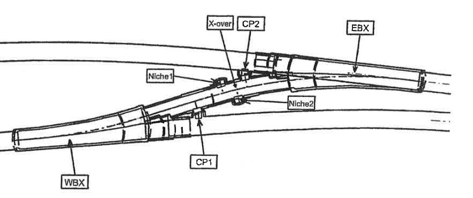
Phase 2 is the construction of the cross over section. The only point throughout the 42km of line that the two tunnels interact, the section will be used for train maintenance, in the event of a breakdown, in order to clear the line. Work is underway to excavate the ‘binocular sections’…essentially the section on each running tunnel where the tunnel divides in two to form the crossover section. My part of ship from here on in…see the overarching plan for the picture to paint my 1000 words.
Ground
I remember the Great Orator mentioning that the ground is actually quite fundamental….he mentioned it once or twice. The nature and engineering behaviour of the ground in tunneling is obviously critical to the design considerations of the underground structures. Crossrail tunnels have been bored at an average depth of 25m along their length, with the odd fluctuation to avoid existing underground structures. The tunnel boring machines and station tunnels and caverns have been bored/dug with relative ease due to the excavations being conducted largely in the London Clay Group. Having looked at some of the ground investigation data, it seems that this consists of stiff or silty clay ranging right through to mudstone. These Palaeogene marine deposits, I’ve been assured, make for an excellent tunnelling medium, due to their relative homogeneity offering some predictability, and their short term stiffness, which allows brief unloading without collapse, ahead of stabilisation with SCL.
However, in the Fisher St/Farringdon area, the base of the London Clay sits at approximately 30m below Ordanance Datum. This area coincides with a ‘busy’ underground infrastructure network (proximity of Central and Piccadilly Lines, aswell as numerous underground services) which constrains the allignment depth. You will see from the Geological section above that just at the point of constructing arguably the most complex section of works in the allignment, we pitch head first in to the Lambeth Group.
At this stage, its probably worth thinking back to the days of the McGuirk Bluffing Face…a slight nod of recognition toward said lecturer as if I was following, when internally I was in a flat spin. Well, the same thing happened when I was told this; as if I understood immediately the implications of it…I didn’t. So I did some reading!! Yea alright, stop laughing….
This is what I learnt….we’re predominantly in the red/brown or green/grey ‘Upper Mottled Beds’, but there is quite a bit of other stuff (technical term); from fine silty sands, shell beds and sandy flint. Bottom line, its a bit of a mess; in contrast to the relative homogeneity of the London Clay belt, this material is vertically and horizontally inconsistent. For tunneling, this presents risks; potentially water bearing, the excavations could cause a flow of material along failure planes as they are uncovered, major face instability prior to concrete spraying, and greater than expected surface settlement with associated damage to surface structures in prime central London real estate.
The Tunnel Boring Machines have passed through the allignment, without reported incident, and as such I have had a few raised eyebrows for asking what the perceived risks are in relation to our excavation. This would be ok…but I since discovered that the TBM has no means of recording the nature of the ground that it passes through, for its properties, contamination or indeed the ground water regime. So essentially, we’re operating solely on a triangulation of two boreholes located 30m and 20m distant from our crossover section, and a baseline statement in the Geotechnical Baseline Report that the lower aquifer on our location is approximately 30m below the excavtion and is therefore of no significance.
Groundwater
I think that the proximity of the borehole data gives us a fair idea of thewhat the enlargement excavation will uncover, so the primary risk will be in the groundwater regime. We are aware that the Lambeth Group is likely to bear isolated pockets of water; so the water is anticipated but the quantity is unknown. So this leads to a number of risks, (based entirely on ripping off Johns notes…)
- Potential for inundation into the tunnel as a pocket of water is uncovered.
- The Lambeth Group is non-cohesive, so this may lead to an increased risk of heave in the tunnel invert if the resistance to this uplift is less than the head created by this water
- Instability in the face due to ground movements caused by pore water pressure.
I must admit, I’m not yet sure what we’re doing about this, if anything, and so I will revisit in future blogs….
What next?
A part of the Phase 2 works, the binocular section on the westbound tunnel (WBX) has been excavated and the primary lining sprayed.
The construction of the cast in situ secondary lining works will now go ahead, with me firmly installed as the section engineer! Blog to follow….
Hobnobs and concrete
I’ve spent the last couple of weeks bouncing between office based negotiations to continue to try and get the Danville flood protection project off the ground and the HQ site. The former continues to be frustrating; I have spent many hours checking through submittals for USACE approval from the contractor for lift plans, labour training, concrete mix designs, schedules etc – the majority of which I have rejected as they just don’t meet the USACE construction specifications or our Health and Safety requirements manual…frustrating when they have the same documentation that I do to work through and cross-check! They are either trying to cut corners at every opportunity or are still trying to get their heads around defence contractual requirements and rigidity (this is their 1st) – I am optimistic and think it’s the latter, but having seen some of their method errors I am starting to worry about their ability. Work plans to start 7 July, and end Dec.
The HQ site is starting to look remarkably different now that pre-cast curtains are being installed. In a non-official manner I have been assisting the QC team as the QA inspections tend to be purely the final product which quite rightly contain few issues so I am learning far more hitting issues immediately after or during construction alongside the QC team – this has actually made the QA inspections even smoother, plus having a uniformed guy, with a British accent and a USACE hard-hat emblazoned with safety control logos tends to create confusion in the ranks of hard-nosed tobacco-spitting sub-contractors resulting in less-arguments. Despite being ‘qualified’ inspectors, it is interesting how little structural knowledge they have, and I impress myself at explaining to them why rebar is placed where it is as they ever keen to learn as well. I have noted that the QC has a non-purposeful habit of swaying towards areas that the QA inspects the most – for example QC checks on rebar prior to a concrete pour tends to focus on cleanliness of the deck surface and rebar ties, rather than what I’ve continually brought out – ensuring drawings are abided by (and rectified if needed!), spacings are correct and dealt with correctly around vertical conduit, and rebar has the correct clearance vertically and horizontally.
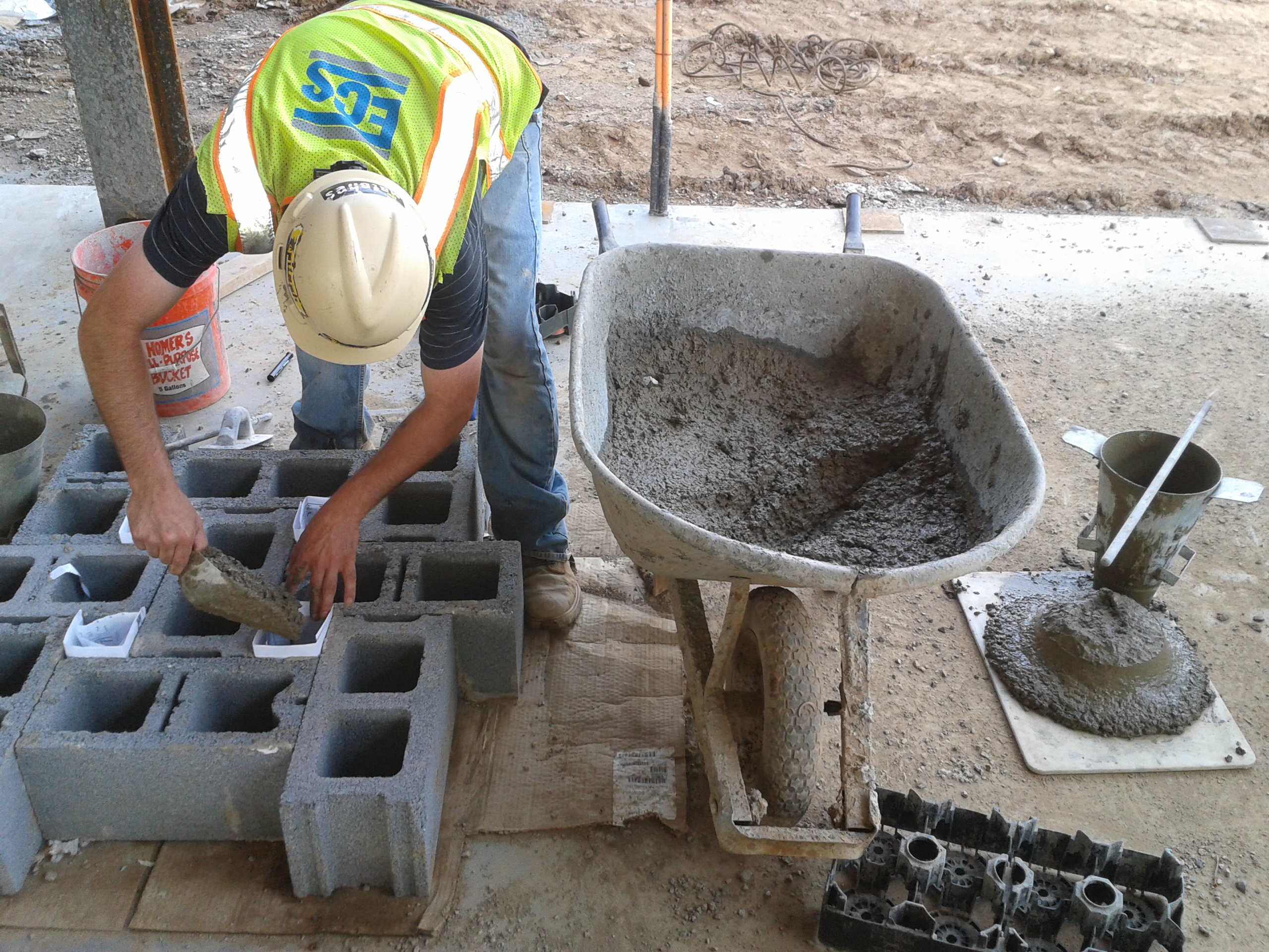
Conscious the blog is a means of sharing in order to educate, rather than just a site-diary I thought some may be interested in some of the testing methods and concrete I am involved in. Deck concrete has to be pumped to three floors high so we’ve used air-entrained, lightweight concrete. This has used pumice as the aggregate – a featherweight volcanic porous rock. Slump tests have been done, as standard, on every 2nd truck, aiming for a slump of 180mm- 230mm, making it very easy to work with. 28 day tests have given a strength of 52000kN/m2, when all that’s desired is 27600kN.m2 – this has consistently been the case! The second on-site test we’ve been doing is to measure the amount of air-voids as it’s air entrained – the specs require 5-7%. Air entrainment tests take one of three forms:
1. Pressure testing: using a pressure device, you measure the air content of fresh concrete based on the pressure-to-volume relationship of Boyles Law. Pressure is applied to the sample to compress the entrained air in the pores, then measures the change in air volume to detremine the air content. We couldn’t use this due to having porous aggregate.
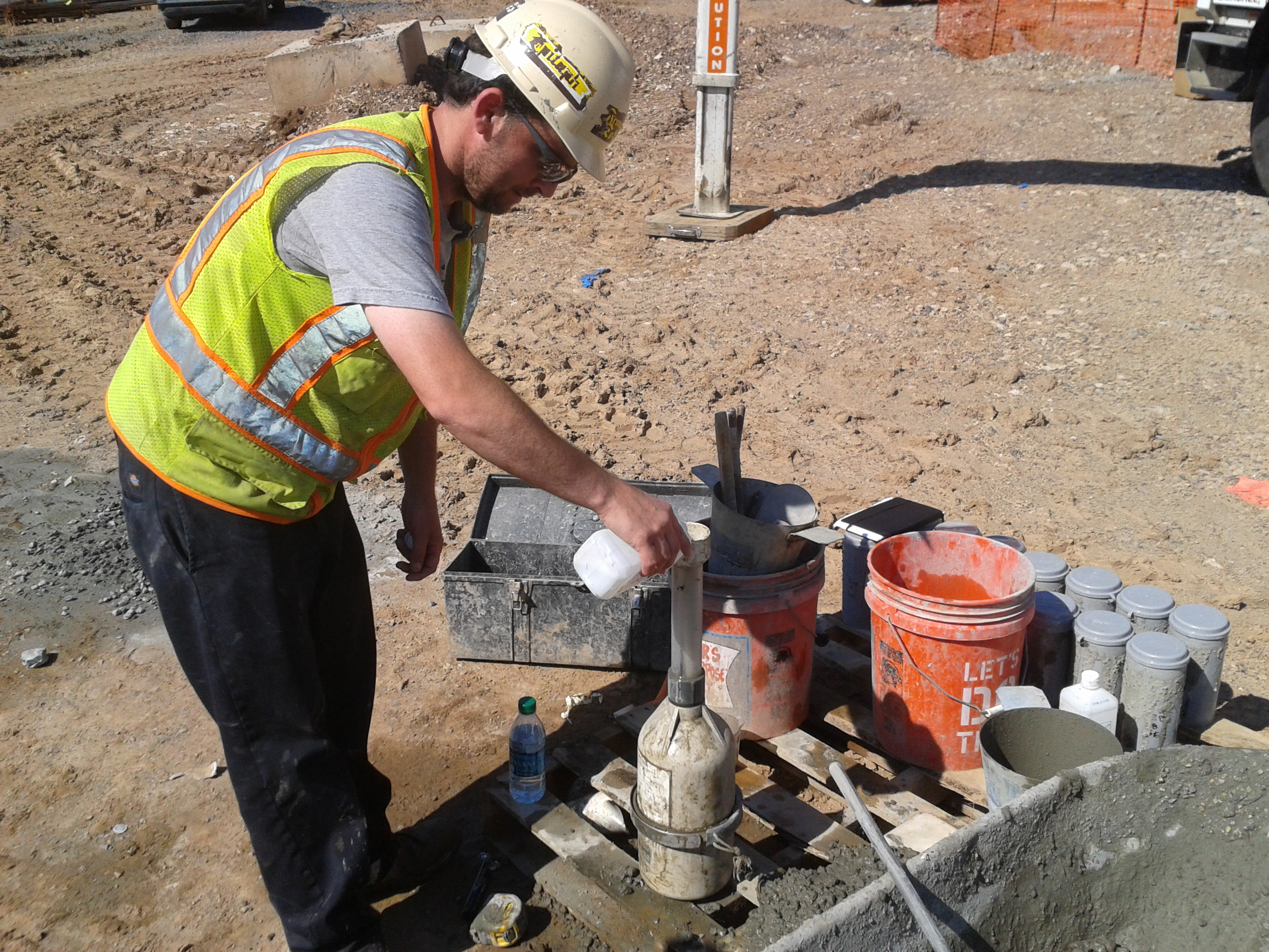
2. The volumetric method or roll method (pictured below). Relying on an instrument with an in-built gauge, it is filled with fresh concrete and agitated with an excess of prescribed water and alcohol.
3. Air Indicator Kit: This kit provides a quick and easy method to check air content. A sample is placed in a vial and alcohol is added to free the air. The change in level of the alcohol in the vial stem indicates the air content.
I have also been conducting grout testing for the stairwell masonry – this has involved the rather non-tech grout block testing pictured below. The paper enables a cube to be moulded whilst also allowing a transfer of water out of the grout to simulate the grout in-situ where the bricks absorb some of the water with cementitious materials in solution. We are still awaiting test results but we require 20500kN/m2; slumps 200-280mm.
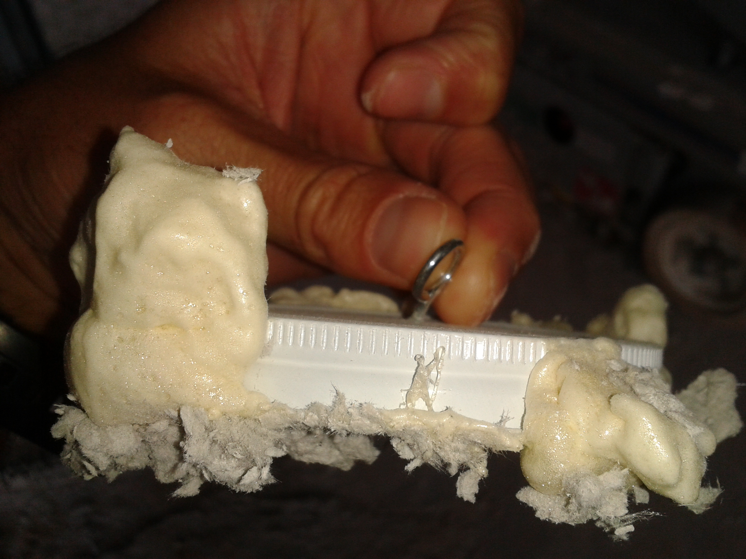
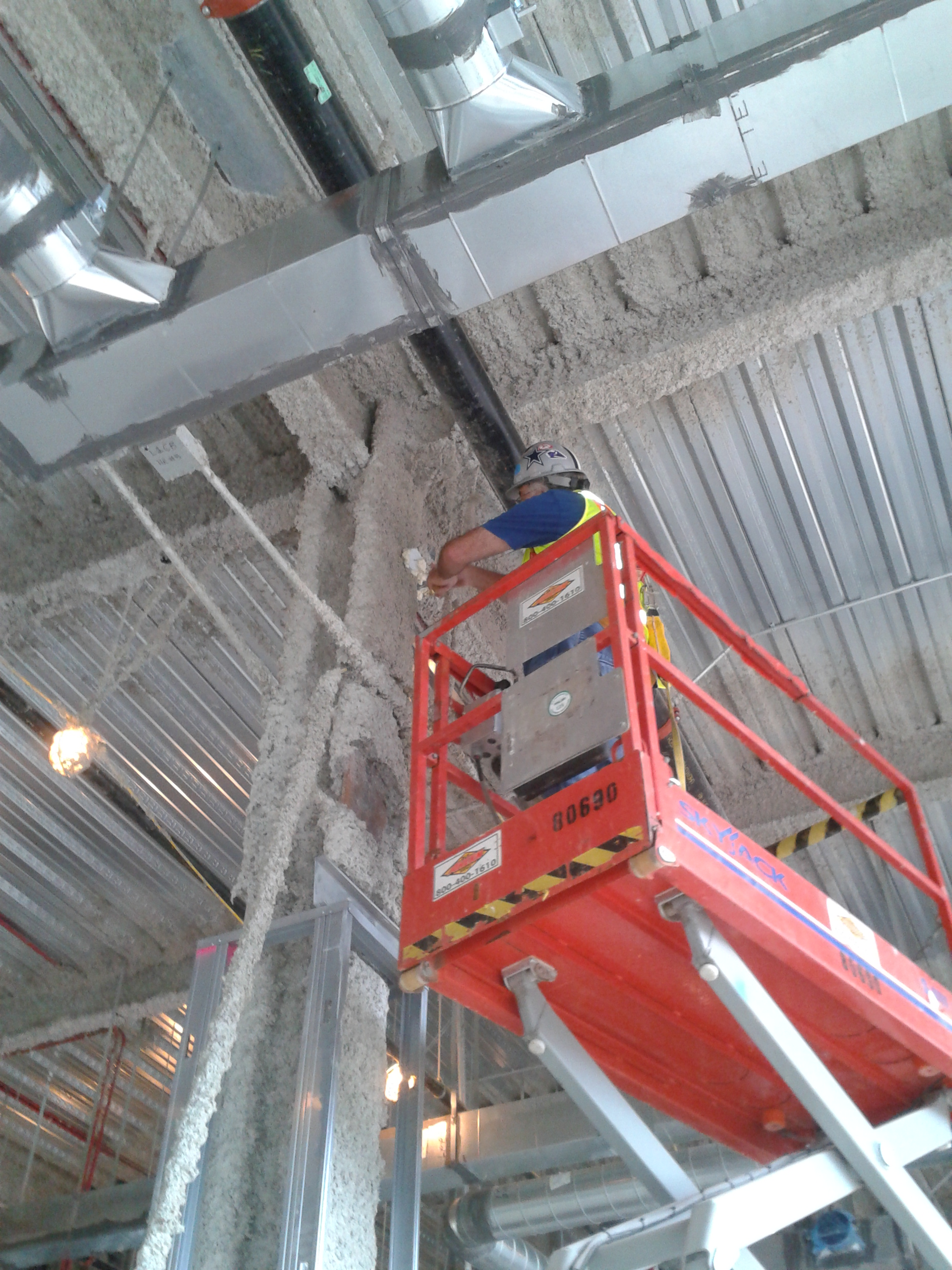
30 days post steel beam fireproofing we’ve jumped onto testing them for density and adhesion. Again, a very crude method but clearly laid out in the ASTM (EC equiv). The density test is done with a 12×9 inch removed area and lab-tested, while the adhesion test is done as follows: a mason jar-like cap with a hook is mastick’d onto random vertical and horizontal areas. After 24hrs of setting, the hook is pulled. In our case with a 1,75 inch thick material it must withstand at least 12psi of pull, unfortunately the material itself broke apart with a mere 5psi….oh dear! This has quickly shot up the pay-grades and we await a plan forward and response from the fireproofing manufacturers!
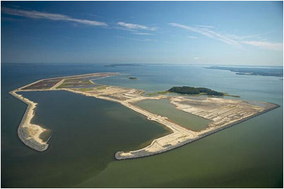
On a side, I made the most of being able to jump on the back of the District Commander’s diary so tagged along for some hobnobbing with a US Congressman who wanted to see the USACE island restoration project in the middle of Chesapeake Bay – Poplar Island. I was blown away…sustainability and PPP’s at its best…reconstituting an eroded island with rock armour and dredged material from Baltimore and Virginia ports and Chesapeake Bay that enables deep water harbours to remain open, prevents open water dumping, all whilst making a carefully balanced ecosystem haven that harbours 1000’s of terrapins and over 180 species of birds acros 7km squared. 2.4million m3 are dredged each year in the areas mentioned; the island at its present perimeter can house 30 million m3 of which 19million has been used; an expansion of the island is being applied for which will enable an aditional 23million to be used.
Goodbye chapter 13……hello chapter 8.
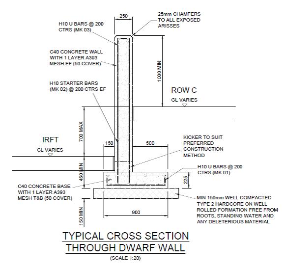
So I mentioned previously that I’m now running with the construction of a 619.310m cantilever dwarf retaining wall stretching the length of the site separating the coal storage area from the biomass handling facilities. In many ways it’s a breeze compared to the previous thrashing of the C620 foundations (hence my upsurge in blogs!) but I don’t want to tempt fate too much at this early stage.
The wall ranges in height from around 1m to over 3m with 2 distinct gradients and a varying footprint profile. The wall itself is 250mm thick, off set 500m from the edge of a 900mm long base forming a cantilever retaining wall. There are ‘Rainbirds’ positioned at regular intervals that are effectively large plinths supporting a water suppression system (to limit the dust) cast into the wall itself and contraction joints every 15m.
As it seems the assist in future discussions (thinking back to numerous piling methodology blogs) this is the construction process:
I mark out the base centre-line with the TS and off set 600mm either side allowing 100mm for a little extra space for the steel fixers to work in. Then set the height on the laser level and get the excavator in to dig to the correct level – usually about 500mm below the prepared ground surface. Compact some type 2 aggregate into the excavation and order some ST1-S3 concrete for blinding and get that in to a depth of 50mm.
I then get out the TS again and set nails in the blinding for edge of concrete at the base and the centreline of the off-set wall for the starter bars.
I’ll check the steel alignment and then order C32/40 S3 concrete and pour the 225mm base. I have been instructed not to place shuttering parallel to the direction of the wall on either side for speed and as the excavation is only 100mm extra either side the additional concrete wasted has been accepted.
As a side issue – the excavation is usually a touch bigger than 100mm either side (operator) so assume 620m of 300mm additional excavation at 225mm depth. A quick time/cost analysis of 620m of 300mm additional excavation at 225mm deep is 42m3 of wasted structural concrete at £65 a m3 = £2730. That’s 68 hours-worth of time for 2 labourers at £20 an hour to fit some reusable shuttering either side. It would take them significantly less time as it would only require single planks and minimal bracing and thus could be a small saving but I suppose it’s a drop in the ocean in the grand scheme of things. The counter argument is the time saved but I have the base slab poured at least 60m+ in advance of the much more time consuming wall construction.
Anyway, I then get out the TS again and set nails in the structural concrete base for the lines of the wall (250mm apart) and the expansion joint positions and hope that the starter bars have not moved during the base pour and appear in the correct position inside the wall makers!
The shuttering is then placed on the rear side of the wall and I use the dumpy level to put nails into the rear shuttering dictating the correct gradient for the top of the wall (1/143). This allows the joiners to place the chamfer filet. Once in place the steel fixers move in and erect the internal wall steel (just mesh) using the filet as there TOC measure to allow 50mm cover.
I then check the steel and horizontal cover prior to the front wall face shuttering being placed and second filet line positioned. Once the shuttering is complete I have been using the TS to check the top alignment of the shuttering which as long as they have used my original nails in the base and kept it vertical it has generally been within 5mm, therefore acceptable. The wall section is then poured using a 2m3 skip and crane.
The interesting issue the wall has raised is in the contraction joint detail and there has been much discussion as to what a ‘formed day joint’ (as can be seen on the picture below) entails.
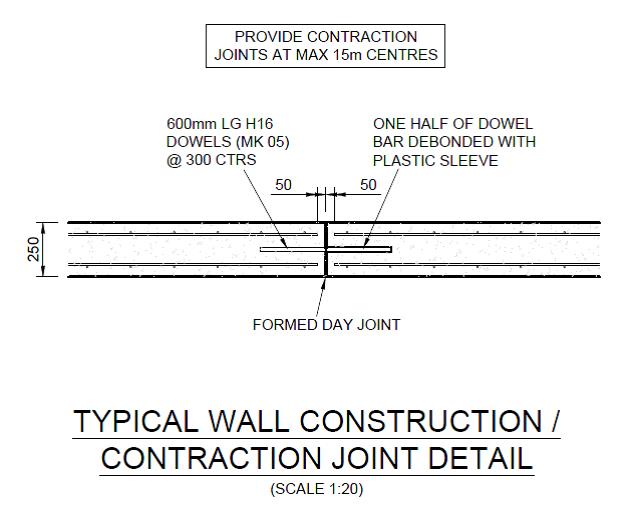
My understanding is that this is a contraction and expansion joint justified by the use of the 600mm half debonded dowels placed at 300mm centres, connecting each wall section. These are a common feature of expansion joints as the sections are tied together by these dowels but the sleeving in one of the sections allows expansion to take place without generating additional stresses within the wall. Expansion joints also feature a definitive gap between the sections to accommodate this potential movement and reduce the risk of potentially damaging forces with the structure. Clearly this gap and dowel also serve to accommodate contraction of the concrete.
To facilitate the gap of the expansion joint I have been placing 10mm sheets of flexi cell inbetween the wall sections to create the gap. These will then have 15-20mm cut away from the exposed edge and a rubber sealant will be used to waterproof the joint. The picture below shows the joint with the flexi cell prior to the sealant. This flexi cell allows contraction and expansion and increases the protection against corrosion of the steel dowels if the gap was not filled. This is the method that the joiners/fixers have used across the site for similar joints.

Questions have been asked (by other engineers) as to why I’m doing this? Their understanding of a formed day joint is simply a construction joint ie you pour up to the end of the section, allow the concrete to cure and simply pour the next section on another day from that surface. Even if a very thin divider was used to ensure clean edges this joint would surely allow only contraction and almost negligible expansion.
The GA does detail a ‘construction / contraction joint’ . A contraction joint only accommodates shrinkage so the correct procedure, by the title, is likely to not involve flexi-cell. However the use of dowel bars to accommodate contraction alone is surely a bit ‘belt and braces’ and indicates the requirement for an expansion capability?
Incidentally the concrete has contracted during the curing process, as can be seen in the flexi cell photo above. This would subsequently leave a more significant gap for future expansion if a simple construction joint was used but surely the dowel bars would be too exposed with a clear gap?
I must add that I have not been flying solo with this and checked the procedure with the MS (which mentions flexi-cell) and my line manager prior to cracking on.
Thoughts?
Corridor of Death – The drama continues
Fredon our Mechanical Sub-contractor have become that Spr which your OC always warns you about that will take up 90% of your time because they are the problem child, Fredon is it!! They have been putting up pipe in the corridor now for over 8 weeks and have achieved about 50 to 60 metres! It has become increasingly contractual and I have spent a lot of my time making a case file against them as they have the audacity to send through delay notices. We now have a workshop with them on a weekly basis, which is micromanaging them and to be honest we would be better off managing them ourselves.
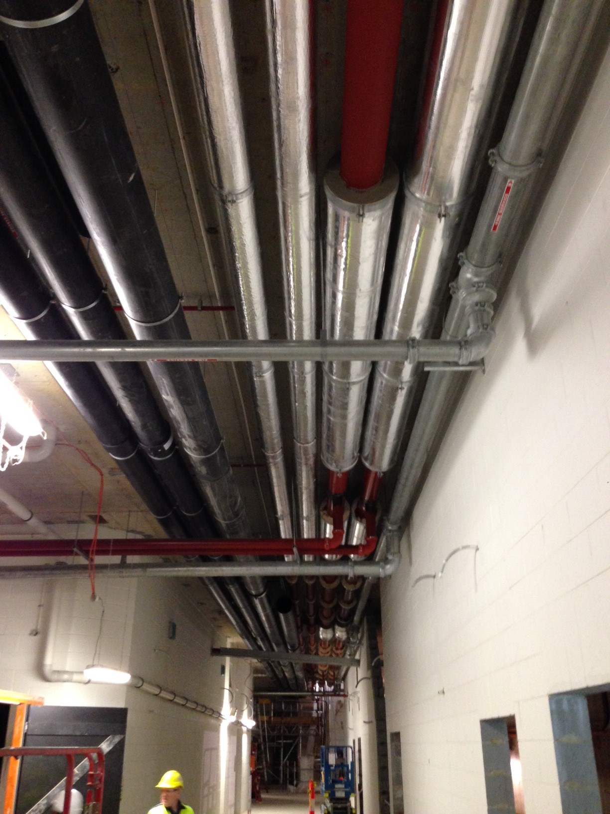
But we have made progress!! We had to coach them through the welding process to ensure that they did sample welds, the welders where qualified, we inspected the welds and ensured they documented all the welds. We then had to ensure they painted the pipe as they were all rusty, now we are lagging the pipe and the Client (State) are not happy which will be todays work. We have completed everything to specification and closely monitored it so we could avoid this.
On a positive note I have been to multiple pump Factory Acceptance Tests (FAT) and Mark thank you the pump knowledge is invaluable, I even sound like I have some idea what I am talking about!! We have also installed our first switch board to the Northern Substation which comes in two parts for shipping which will be bolted together today. I also attended the FAT for that and again John the electrical knowledge was invaluable.
Overall a lot of fire fighting and less of what we should be doing but all great experience learning something new everyday.
C620?? Done. Blog No 5.
As I mentioned in reply to my previous blog comments I am now running with the construction of a 619.310m retaining wall but before I discuss the details and issues already surrounding this wall I will conclude with a few more details on C620 and another reflection.
I will also add a few photos to the shopping list style of activities I included for Blog 4 as I now have a working phone again!
The foundation for Transfer Tower 535 (shown below) gives you an idea of the main foundation bases constructed (x3) and the type of layout of the services, deluge pipes, transfer beams, cladding upstands, gravel POL pits for the mechanical services, plinths and irregular off set bolt pads. All reasonably complex for a first timer!! The first picture below is taken from Blog 3 just after I had finished the excavation of TT535, the second picture shows the completed foundation.

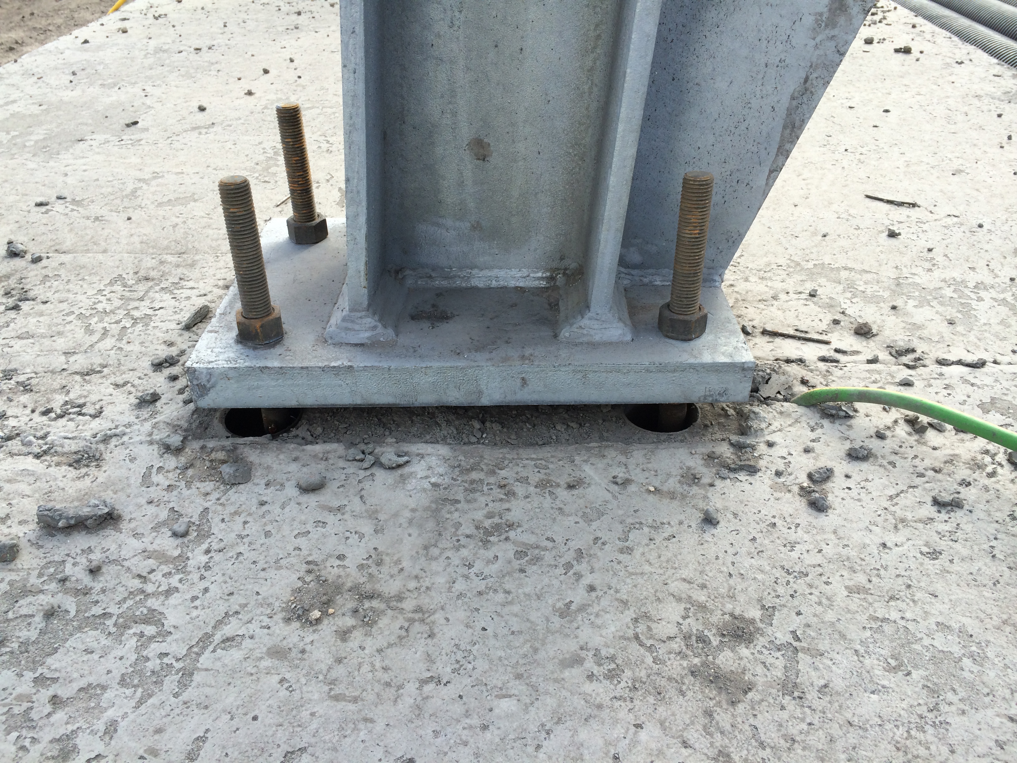
The steel trestles are now going up in earnest on the smaller trestle bases (4 of 8 to date) and they continue to fit – fingers crossed for the rest. The first photograph below shows a Trestle 10 column base plate fixed into position. The 25mm gap below the plate has been packed out and will be grouted to set the position. The photograph below that shows the exposed elements of the foundation for Trestle 10. Each slab had a deep foundation of 8 x PC RC 26m piles and housed 2 x bolt pads. They were connected by 2 parallel transfer beams running between the pads (now buried) that provided the platform for the small plinths, accompanying bolt pads and the stair beam. More importantly they reduce the risk of differential settlement across the 2 pads that the intolerant mechanical structure and services placed onto them cannot take.

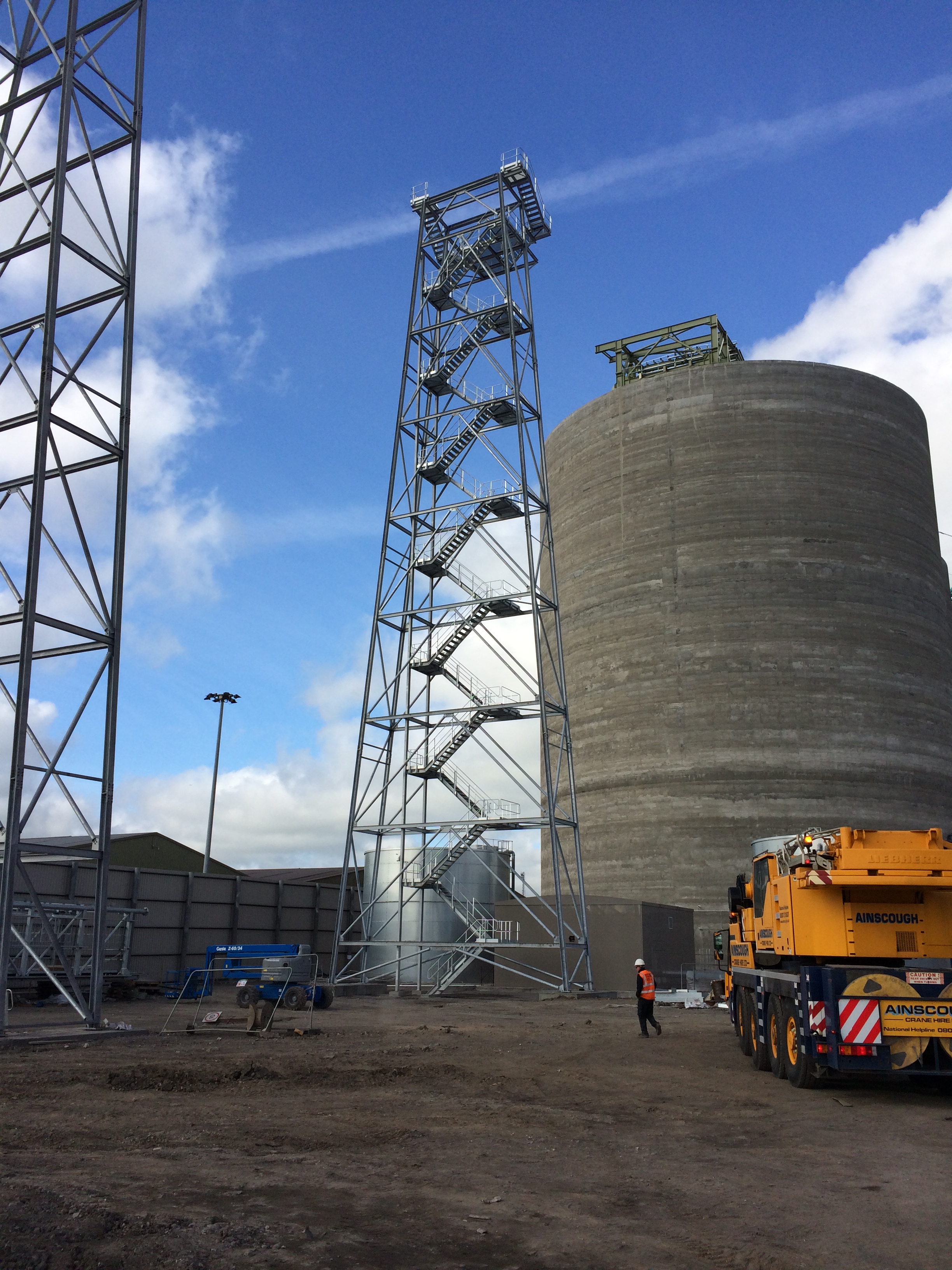
Trestle 10 is now complete and is the largest of all the trestles taking the conveyor up to the top of the Biomass storage silos.
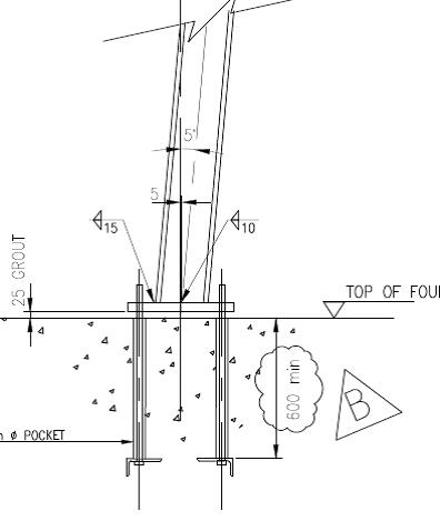
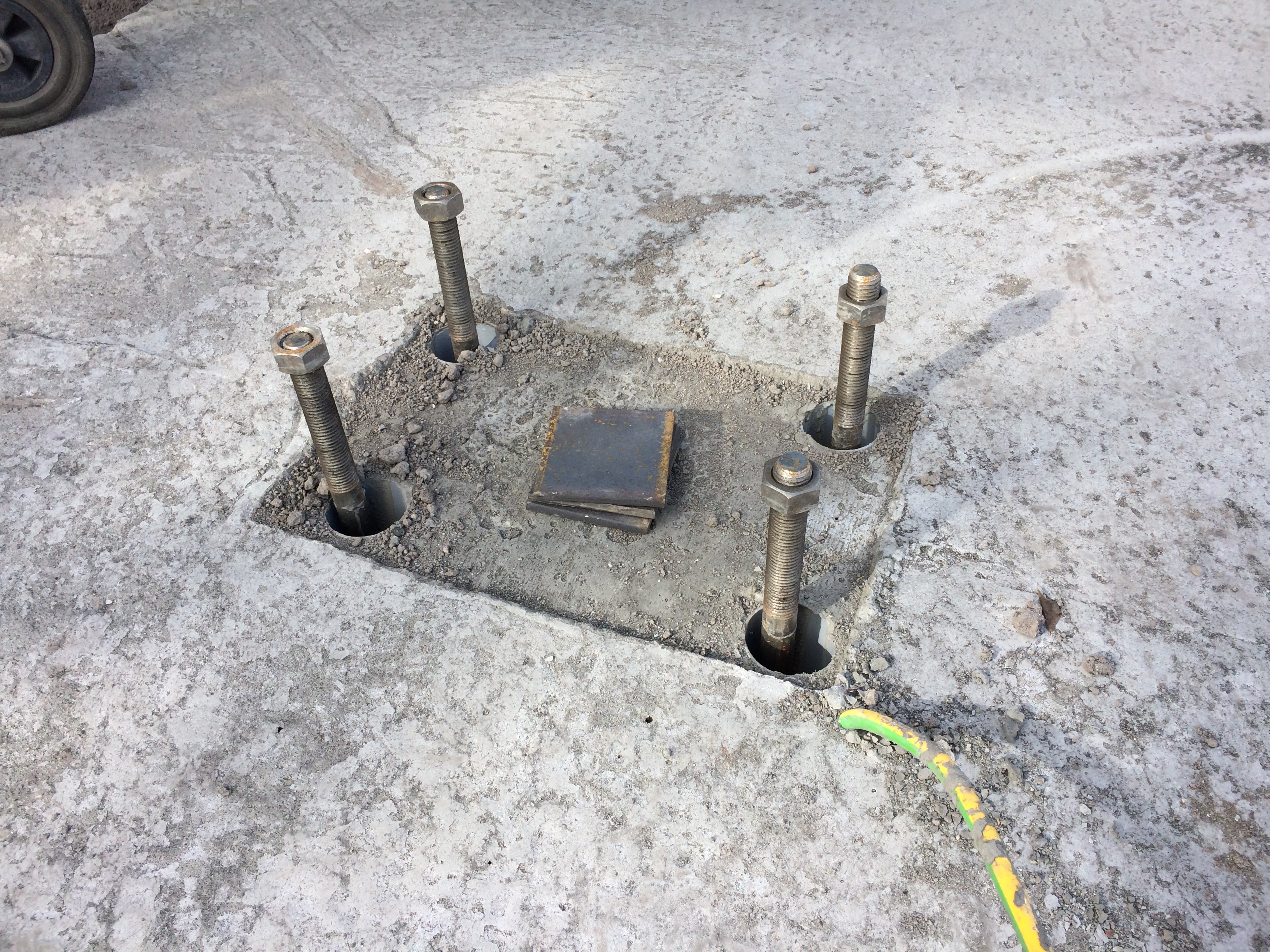
The bolt pads are made in advance and fixed into plywood templates that match the column base plate exactly. The bolts are placed into 60mm drain pipe cut to length acting as a void former to allow some horizontal movement for ease of placement and take out any setting out error. The trestle foundations were designed for compression and tension (predominately due to the wind loading on the high structures) and as such additional steel right angle plates were fixed to the ends of the bolts to increase the resistance to the tensile force. The design and finished in-place bolt pad (template removed) can be seen below.
These were a pain to place as the steel cages had been pre-fabricated and lowered into place prior to the placement of the bolts and trying to attach the heavy steel right angle plates onto bolts through and 700mm deep into a 1000mm deep steel cage was tricky.
I set out the nails for the placement of the bolts, stringlines were used to set the correct position and wooden cross bracing was used to fix the pads to the correct height and location. On the first foundation featuring these plated pads we used the addition of steel tying wire to hold them into position. I quickly discovered this was not enough.
Issue. The specification for the C32/40 concrete used in the C620 foundations was for consistence class S3 and a max W/C ratio of 0.45 giving a target slump of between 100-150mm (-20mm, +30mm) and generally the team liked it at 150mm+ for ease of placement. On one of the initial pours where these particular plated bolt pads were used we had an arrival slump of 90mm which I said was acceptable, as per the guidelines, and instructed the team to begin pouring. Due to the plates on the pads and the stiffer concrete mix the bolt pads rotated and moved significantly causing me a real headache as we quickly reset the lines and used various levers and improvised methods to work them back into position. This was all to the continuous backdrop of ‘I told you it was too stiff’ from the concrete team. Thanks.
Solution. For subsequent pours I held the lorry until the slump test was conducted, used a Graham Construction slump adjustment chart to get the predicted slump to around 150mm, tested it again (if there was enough time) and poured with much greater success. In addition I insisted that steel Z bars were used to brace the bottom of the plates to the top of the steel cage and they were quickly tacked into place by the welder. This resulted in a much smoother pour and significantly less stress/abuse for me.
Reflection. The reflection from this issue was one of quality control and the difficulties surrounding it. Enforcing it has made me unpopular on a number of occasions. This site is over 18months through the project and the team of sub-contractors have been together since the start, working with LaFarge the concrete suppliers. ESG are sub contracted to conduct a slump test on all loads and 1 cube test per day or every 10 lorry loads however it has become site practice to get the cubes done every 20m3 (approx. 3-4 lorry loads). I have witnessed poor practice on a number of occasions across the site as a lorry would turn up, the slump and cubes would be taken and then the mix would be wetted up to suit the pourers and placed. On my section, to prevent this, I would have to physically stop the wagon, insist on the slump being taken, adjust the mix as required, slump test it again and then get the cubes taken. As long as I kept it within the guidelines stated above, which at the upper end was more than workable enough for the concrete team, I could not understand their reluctance to do the right thing? Quality control and assurance are vital in this a marine environment and I could only put it down to the additional time (probably no more than 10mins) it took to complete as they just want to ‘get it done’ as the subcontractor is paid per m3 of concrete poured.
There were obviously more learning points and issues that I have captured for my DO’s but having discussed responsibility, speed and accuracy, services, piling problems and solutions, more piling problems, construction methodology, ground investigation, risk, concreting and quality control I feel I can put C620 to bed for the blogs and save some final bits for AER2.
I will now start drafting a blog for another issue I already have for my retaining wall!
All trains from Victoria CANCELLED…….
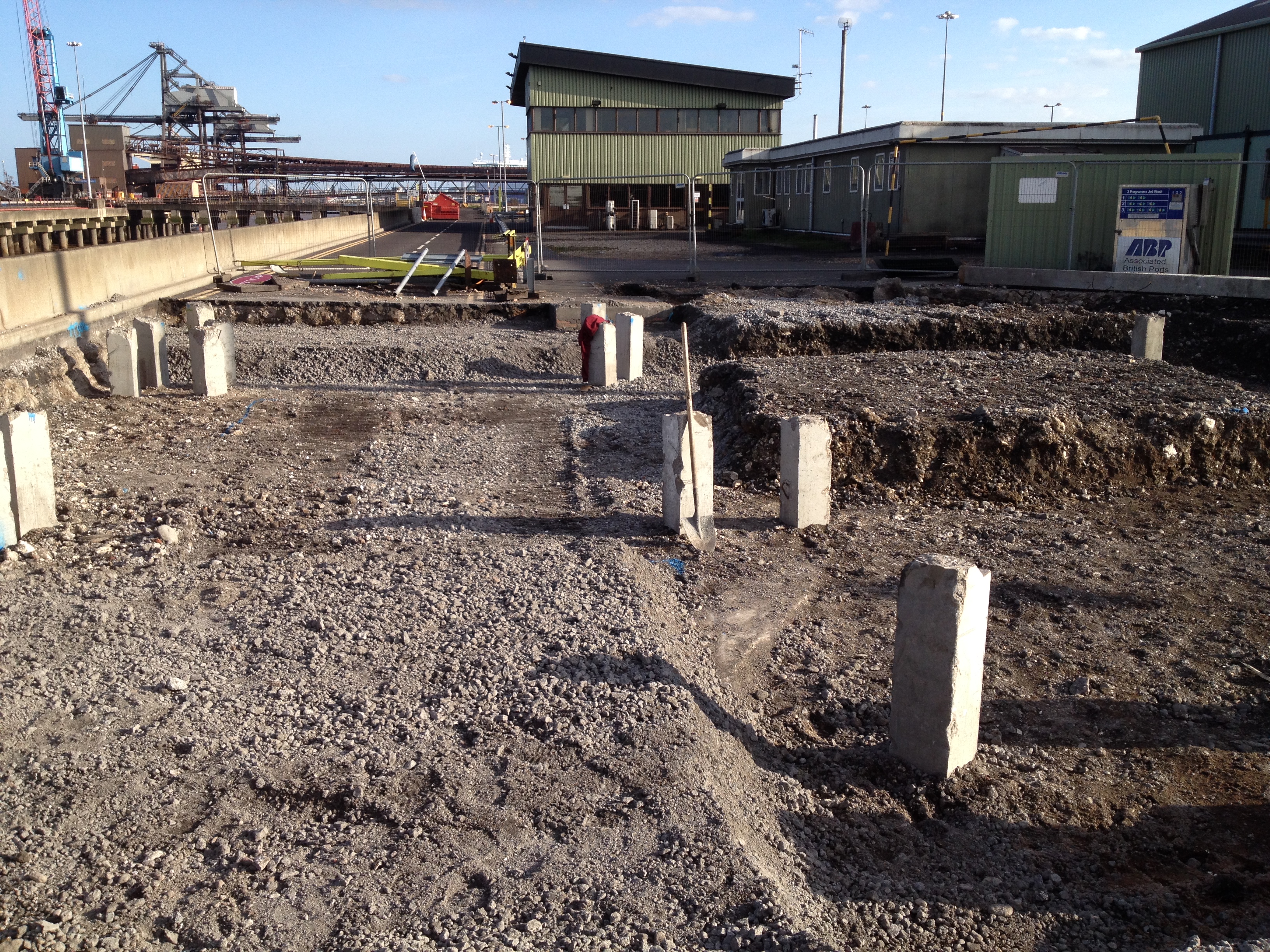
Well today I was in my element utilising my military skills and my search advisor knowledge! It involved 5 police cars, 3 fire engines, an ambulance, the evacuation of the site, closure of Battersea Heliport and all train lines coming from Victoria. At around 1430 Hrs one of the engineers came up to the office saying that the piling rig had dug something up that could be UXO. Being the only person that vaguely knew one end of a bomb from the other I agreed to go and give my expert guestimate of whether we should be running for cover.
On arriving at the piling rig I found this:
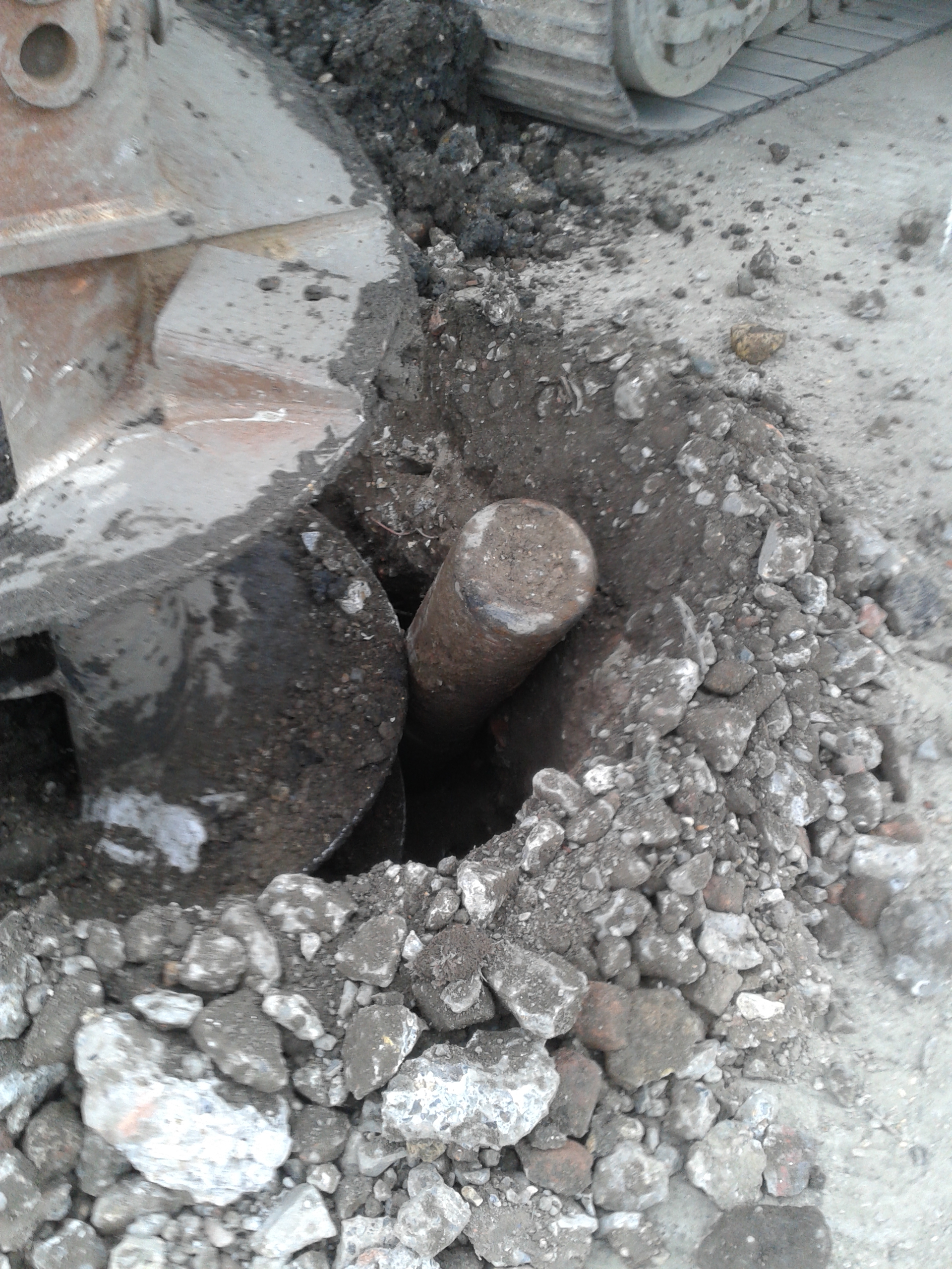
It was around 150mm diameter all the way down with no tail fins or pointy ends so I was 90% sure it wasn’t going to start ticking at us. I took some photos to brief the services and then cleared my area of responsibility of operatives. As the site was getting evacuated I found the piling rig operators and used the search advisor questioning technique to find out what they were doing when they found it and what actually happened. The rig was drilling the pre-bore for the casing when it hit a metal obstruction about 1.5m BGL. On moving the auger forwards and up, it uncovered the metal object that started hissing. At that point the rig crew stopped work and promptly left the area to raise the concern. We got the site evacuated and after around 45 minutes 4 police cars turned up.
I ended up briefing the police and showing the photos with the senior construction manager and an ex-RE policeman went down to have a look. He confirmed our suspicions that is was more likely to be an oxygen or acetylene cylinder and the police decided to establish a 400m cordon. With the train lines around 30m away and the cylinder pointing straight at them and the flats the other side of them-all the trains from Victoria were cancelled and the flats started to be evacuated. Finally the fire brigade turned up and I had my briefing map and photos ready. It reminded me of the old 4Cs operation we got taught on PDT for Iraq. After seeing the photos they reduced the exclusion zone to 200m and they sent some guys with breathing apparatus to go and check it out despite the fact we had been stood next to it over an hour before!
To cut a long story short, they confirmed what we had told them and went with the construction manager’s plan of attaching some strops to it to support it and reversing the auger to lift it from the hole. Low and behold it worked without going bang and everyone went home for tea and medals and the trains set off again.
Here’s the culprit:
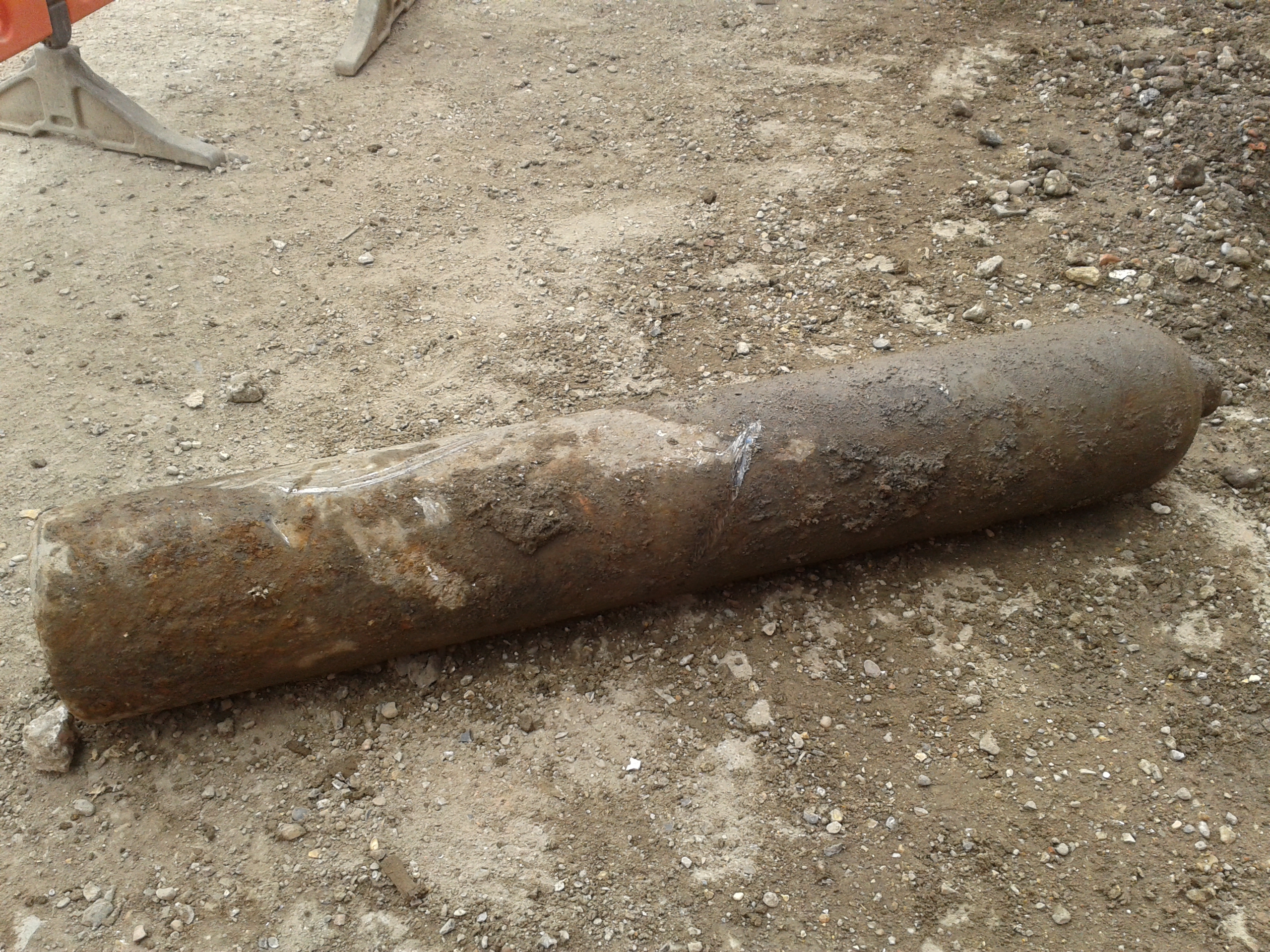
We are not sure exactly where it came from but it looks like it was between our pile mat and another piece of terram. It may have been buried during the backfilling of a previous dig or development prior to us being on site. It is likely to throw up a whole world of debate about whether excavation and piling on the site is safe as if they had struck the cylinder straight on it could have exploded. It will also be interesting to see whether the client ends up footing a bill for the closure of the railway line or whether incidents like this outside our control are excluded. One thing I will be implementing on site is a proper laminated briefing map and some advice on how to control incidents. I was amazed with how many people rushed to take the afternoon off, leaving a couple of people to deal with everything. Even the police and fire brigade didn’t really seem to take command and control as I would have expected them to do. I am more institutionalised than I thought!
Charity Engineering Development
Early in my in my attachment volunteered to take part in a charity cycle ride from London to Paris, of course wanting to prove my physical prowess I instantly said yes with little knowledge of really how far it was or what the charity did. The weekend just gone was the date set for the cycle ride and I’m pleased to say the team of carefully selected office athletes set of from outside of Liverpool street station on Friday morning and arrived under the Eiffel tower late Sunday afternoon. Having now completed the cycle ride and having hounded others within the office for sponsorship I thought I better really understand what it was i raised money for, i knew it was for third world development but what was the money actually for…
The charity is called Engineers For Overseas Development (EFOD) and is a voluntary organisation that aims to enhances the training of young professionals by challenging them to deliver development projects overseas. Over the last 13 years EFOD have delivered a diverse number of projects to communities in central Africa (Uganda, Zambia and Ghana) .
Examples of past projects include:
• A medical waste incinerator at Kumi Hospital, Uganda (EFOD North-West);
• The design and construction of a footbridge over the Kanakantapa river in Zambia (EFOD Wales);
• The Sewing School in Kpone Saduasi, Ghana (EFOD South-West); and
• A community centre for a women’s co-operative farming group in Koutulai, Uganda (EFOD West Midlands).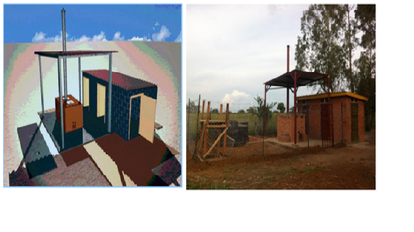
Designed and Completed Incinerator, Kumi Hospital
This year’s project is the improvement of infrastructure critical to the running of a hospital in Kuma, Uganda. The scope of the project for 2014 is; to improve the water pump, currently a broken diesel pump, to improve supply to the hospital, construction of more sustainable and hygienic latrines, improving the laundry facilities within the hospital.
The projects looks to utilise and practice junior engineers in applying engineering principles to design both structures and M&E services. The junior engineers are also responsible for the commercial process and al other aspects of managing the project from concept through to final handover. While not all the engineers will travel to Uganda all will contribute to the project. Having had a little experience of delivering engineering projects within Kenya and Afghanistan i was asked if I might be able to assist by means of reviewing projects and imparting any advice to the junior engineers on project managing such a project.
During the two short periods that I attended with the EFOD engineers and during the review of their initial designs and concepts the key themes that I feel I helped to develop area as follows:
Sustainable – considering environmental impacts, future community needs, and the longevity of the design
Buildable – with local resources, taking into account local knowledge, available expertise and skill levels
Maintainable – using a maintenance scheme appropriate to local skills, which are strengthened through EFOD provided training
Affordable – delivering required outcomes with the funds raised
Ground reality – H&S regs will not be to the UK standards and would be very hard to enforce, therefore work with what is acceptable risk and implement measures where possible.
