140 Elephant Hangers
The South Bank Tower extension from 30 to 42 storeys is based upon the requirement that all vertical loads must be transmitted down the existing core to the foundations.
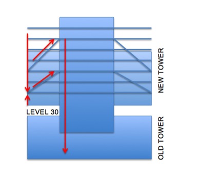
In order to do this, the floors outside of the core will be hung, supported by angled steel bars that drop down from 2 or 3 storeys above. In plan, there are three hanger locations, NW NE and SW corners (see red below). Each corner has an upper set and lower set, as can be seen above (blue diagonals).
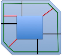
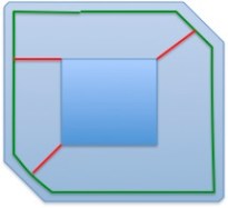
The NE and SW hangers (in red now above) each have three bars. Each bar is 100mm in diameter and is to be supplied and installed by Macalloy. Since the NW hanger supports a small floor area there are only two bars on each set. The Macalloy bars pick up load from a ring beam (in green above). The ring beam spans from the wing walls (in black above) between Level 30 and Level 35. Above Level 35 there are no wing walls and the ring beam extends around the entire building (as below).
The challenge therefore is taking the high resultant verticals loads (7600kN in disproportionate collapse = 140 elephants) that drop onto the Macalloy bars and transferring it safely into the RC core. This steel to concrete connection (the hanger) is the key element of the building and the lack of detail from our Structural Engineer has added a degree of friction to the planning and design of these elements (ref last post).
Constructability
The 12-storey reinforced concrete tower core extension is going to be built with a slipform rig. The slipform rig will not allow the corner hangers to be installed as the slip passes each hanger location. Therefore large pockets, or voids, will be left at each hanger location. Over the past month I have worked on the size of each pocket, what infill (or strengthening) is required around each to ensure the temporary stability of the tower, as well as the sequence of offering the hanger into the building and making good.
The general sequence is
1 Slipform launches from Level 30
2 Slipform leaves pockets at each hanger location (six in total)
3 Floor plates internal to the core follow the slip with a 3 floor delay
4 Slipform reaches Level 42 and is dismantled
5 The floor slab adjacent to each hanger is post tensioned, once the concrete is up to design strength.
6 Access is now possible to the hangers with the crane and the hanger is installed.
7 The Macalloy bars are attached and can suspend the steel frame exterior to the core, and later composite slabs.
The Steel to Concrete Connection
The principle of the corner hanger is to resolve the diagonal Macalloy force into a vertical and horizontal components.
The horizontal force component passes along post-tensioned cables that are anchored within a 400mm thick slab. Macalloy rods are planned to be used (not confirmed) and they will lie in the middle of the slab with no change of eccentricity. The PT slab is heavily reinforced to allow the tensile loads in the tendon to pass right through the entire core slab. Outside of the PT slab the floor is only 200mm thick.
The vertical component employs both bearing and shear keys (within the hanger) to transit the vertical compression into the walls of the core. The shear key uses three 350x350mm SHS sections (filled with grout) to engage the concrete within the walls. The key issue for us is maintaining wall reinforcement continuity into the hanger.
The way we plan to do this is by leaving couplers accessible on the edge of the void as the slipform passes. The corner hanger will be offered up in two phases. First the inside plate, with SHS sections, is lifted and positioned. Then the rebar is fixed within the hanger (and attached to the couplers left in the walls), the outside plates are welded on, and finally the hanger is filled with concrete.
The risk here is that air pockets might form within the hanger and this will significantly affect the bearing ability of the hanger.
The Issues & resolutions
- Size of the void
o We have opted to weld the hanger on site. This limits the size of the void since the lapping of rebar will happen inside, instead of outside the core. However the quality of the weld may be reduced. My input was to conduct prelim analysis of the viability of options an then a detailed examination to highlight issues to the Struct Engrs.
- Rebar displacement and continuity inside and around the hanger.
o The SHS sections block horizontal and vertical rebar. The base plate blocks vertical rebar.
o Therefore holes will be drilled in the base plate and rebar will be displaced to avoid the SHS sections. The detailed examination again identified issues and I was able to propose minor design changes.
- Temporary strengthening around the voids.
o How much strengthening is required for local and global stability? How will it affect later construction? What is the cost?
o I looked at RC strengthening, steel and proprietary systems. For global stability we are using further strips of RC to be slipped. For local stability issues the use of proprietary systems allows quick installation.
- The PT slab does not extend through the entire core.
o How will this affect the robustness of the core? Mace have not conducted any examination of the detailed design but since concerns have been raised we are now getting a Category 3 check completed on the hangers.
- There is no tensioned belt around the core at the hanger level.
o What is stopping the corner of the building bursting out from inside the core? This will be covered in the Cat 3 check.
- The Macalloy bars will elongate during construction and throw out construction tolerances.
o How do we plan the elongation and pre-set required at the start of construction. Whose responsibility is it to get it right???
o Do we plan to jack (shorten) the Macalloy bars to achieve the required length later on?
o Will the cables need to be jacked in order to achieve a regular force between them?
o These issues are not bottomed out. AKT are not willing to give preset cambers, or dictate the jacking procedure which we are strongly contending. After all, it is their design and concept, not ours, to screw up!
In all, the past few weeks have been the most interesting but stressful. The slipform is now behind schedule, but has now launches and is at level 33. PC Harringtons are paying the price still for not backing up their engineering design team since temporary works were holding up the construction.

Excellent Blogg Rich, Good solid approach to engineering solutions 🙂 I’ll come back on a few of those (probably rhetorical) questions later if I get time but first thought is that if you’re using couplers ask Steve C-J if he’s prepared to send you copy of his TMR 1 which covers his RC coupler experiences and thoughts in depth.
Yes it’s an interesting robustness issue. There are three ways to tackle robustness…chicken-lickin’ (peripheral ties)- no chance in this situation ; alternative load paths or protected elements
Your building is a class 3 – so it looks like it’s a protected element approach allowing for an agreed overload on the hangars ( hence the elephants – I would guess this is 15% of the floor area collapsing or 100sq m , whichever is less?) I wouldn’t think that there is too much alternative load path to sue?
Rich
This is an excellent Blog and especially as I remember seeing the issue at first hand. Many apologies for not getting back sooner. I still cannot get my head around the fixity of the bars into the central core – a tremendous amount of steel in such a small place. Keep going.
Regards Neil