Archive
Corridor of Death – The drama continues
Fredon our Mechanical Sub-contractor have become that Spr which your OC always warns you about that will take up 90% of your time because they are the problem child, Fredon is it!! They have been putting up pipe in the corridor now for over 8 weeks and have achieved about 50 to 60 metres! It has become increasingly contractual and I have spent a lot of my time making a case file against them as they have the audacity to send through delay notices. We now have a workshop with them on a weekly basis, which is micromanaging them and to be honest we would be better off managing them ourselves.
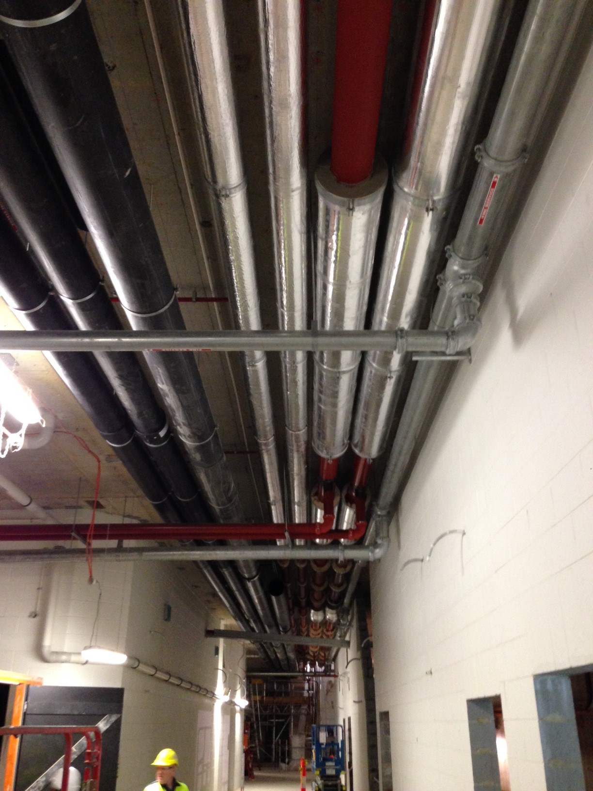
But we have made progress!! We had to coach them through the welding process to ensure that they did sample welds, the welders where qualified, we inspected the welds and ensured they documented all the welds. We then had to ensure they painted the pipe as they were all rusty, now we are lagging the pipe and the Client (State) are not happy which will be todays work. We have completed everything to specification and closely monitored it so we could avoid this.
On a positive note I have been to multiple pump Factory Acceptance Tests (FAT) and Mark thank you the pump knowledge is invaluable, I even sound like I have some idea what I am talking about!! We have also installed our first switch board to the Northern Substation which comes in two parts for shipping which will be bolted together today. I also attended the FAT for that and again John the electrical knowledge was invaluable.
Overall a lot of fire fighting and less of what we should be doing but all great experience learning something new everyday.
C620?? Done. Blog No 5.
As I mentioned in reply to my previous blog comments I am now running with the construction of a 619.310m retaining wall but before I discuss the details and issues already surrounding this wall I will conclude with a few more details on C620 and another reflection.
I will also add a few photos to the shopping list style of activities I included for Blog 4 as I now have a working phone again!
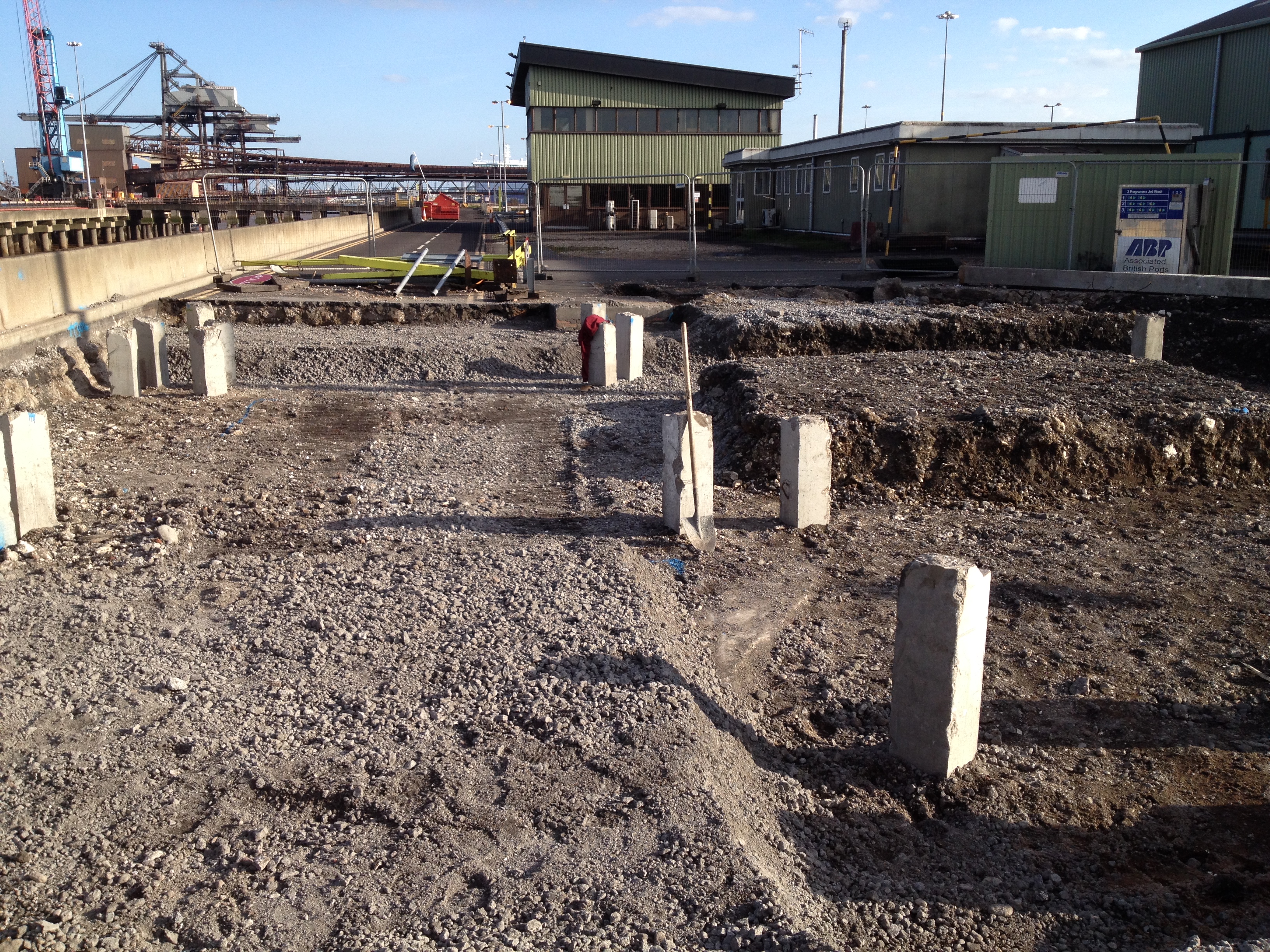
The foundation for Transfer Tower 535 (shown below) gives you an idea of the main foundation bases constructed (x3) and the type of layout of the services, deluge pipes, transfer beams, cladding upstands, gravel POL pits for the mechanical services, plinths and irregular off set bolt pads. All reasonably complex for a first timer!! The first picture below is taken from Blog 3 just after I had finished the excavation of TT535, the second picture shows the completed foundation.

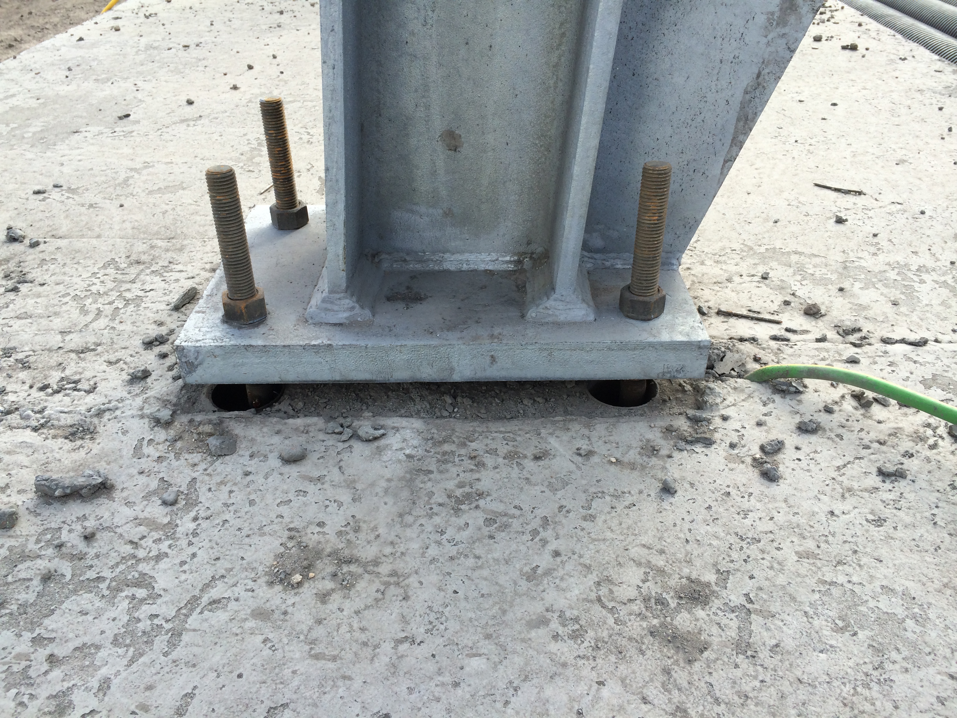
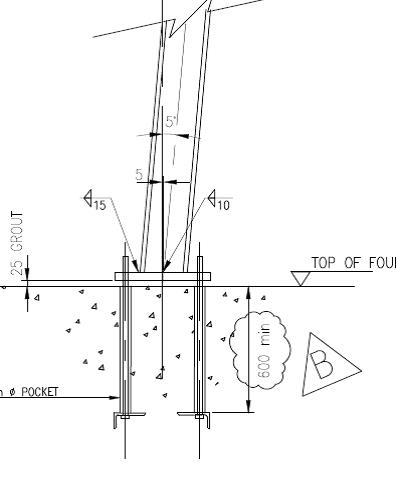
The steel trestles are now going up in earnest on the smaller trestle bases (4 of 8 to date) and they continue to fit – fingers crossed for the rest. The first photograph below shows a Trestle 10 column base plate fixed into position. The 25mm gap below the plate has been packed out and will be grouted to set the position. The photograph below that shows the exposed elements of the foundation for Trestle 10. Each slab had a deep foundation of 8 x PC RC 26m piles and housed 2 x bolt pads. They were connected by 2 parallel transfer beams running between the pads (now buried) that provided the platform for the small plinths, accompanying bolt pads and the stair beam. More importantly they reduce the risk of differential settlement across the 2 pads that the intolerant mechanical structure and services placed onto them cannot take.

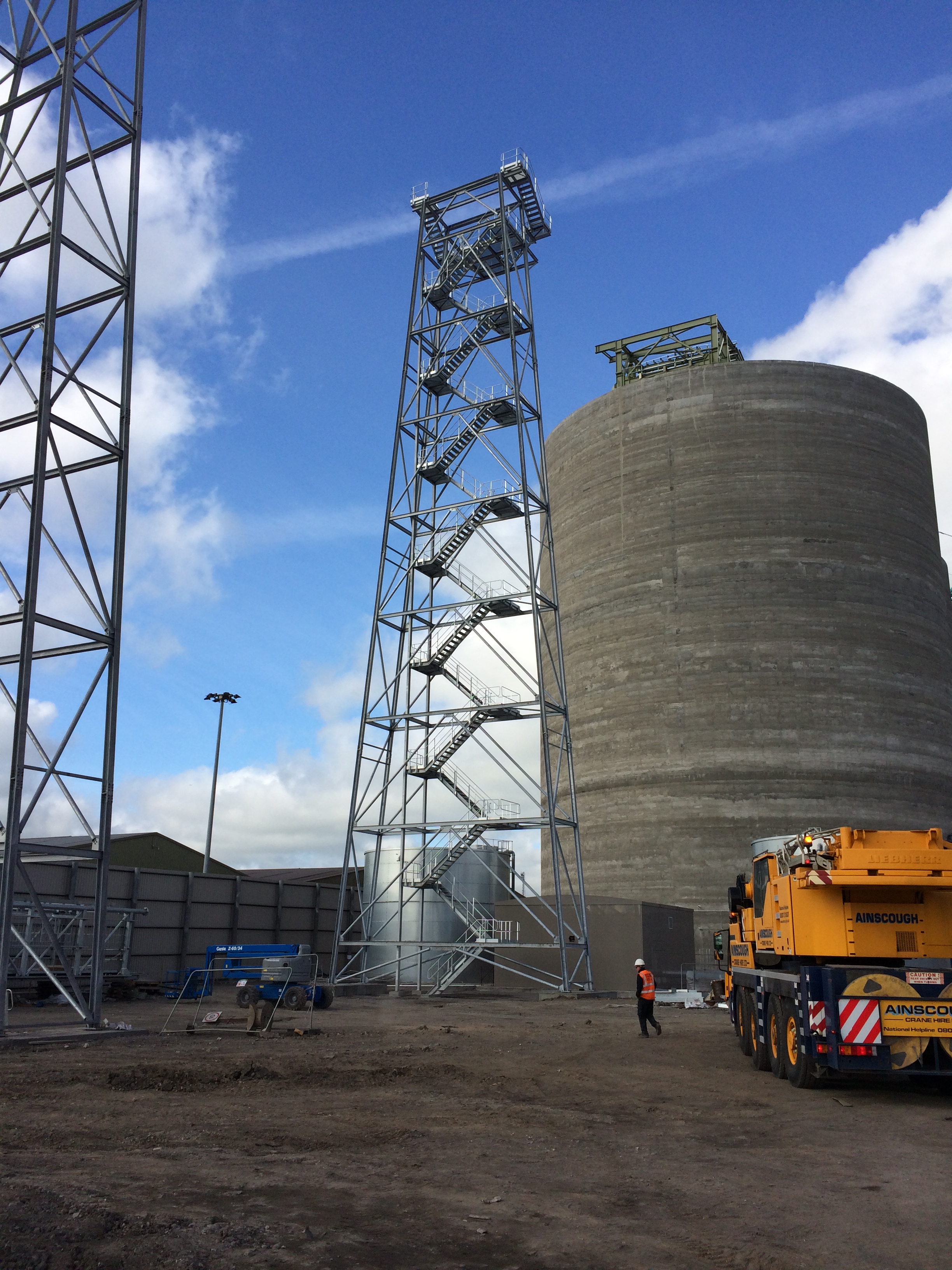
Trestle 10 is now complete and is the largest of all the trestles taking the conveyor up to the top of the Biomass storage silos.
The bolt pads are made in advance and fixed into plywood templates that match the column base plate exactly. The bolts are placed into 60mm drain pipe cut to length acting as a void former to allow some horizontal movement for ease of placement and take out any setting out error. The trestle foundations were designed for compression and tension (predominately due to the wind loading on the high structures) and as such additional steel right angle plates were fixed to the ends of the bolts to increase the resistance to the tensile force. The design and finished in-place bolt pad (template removed) can be seen below.
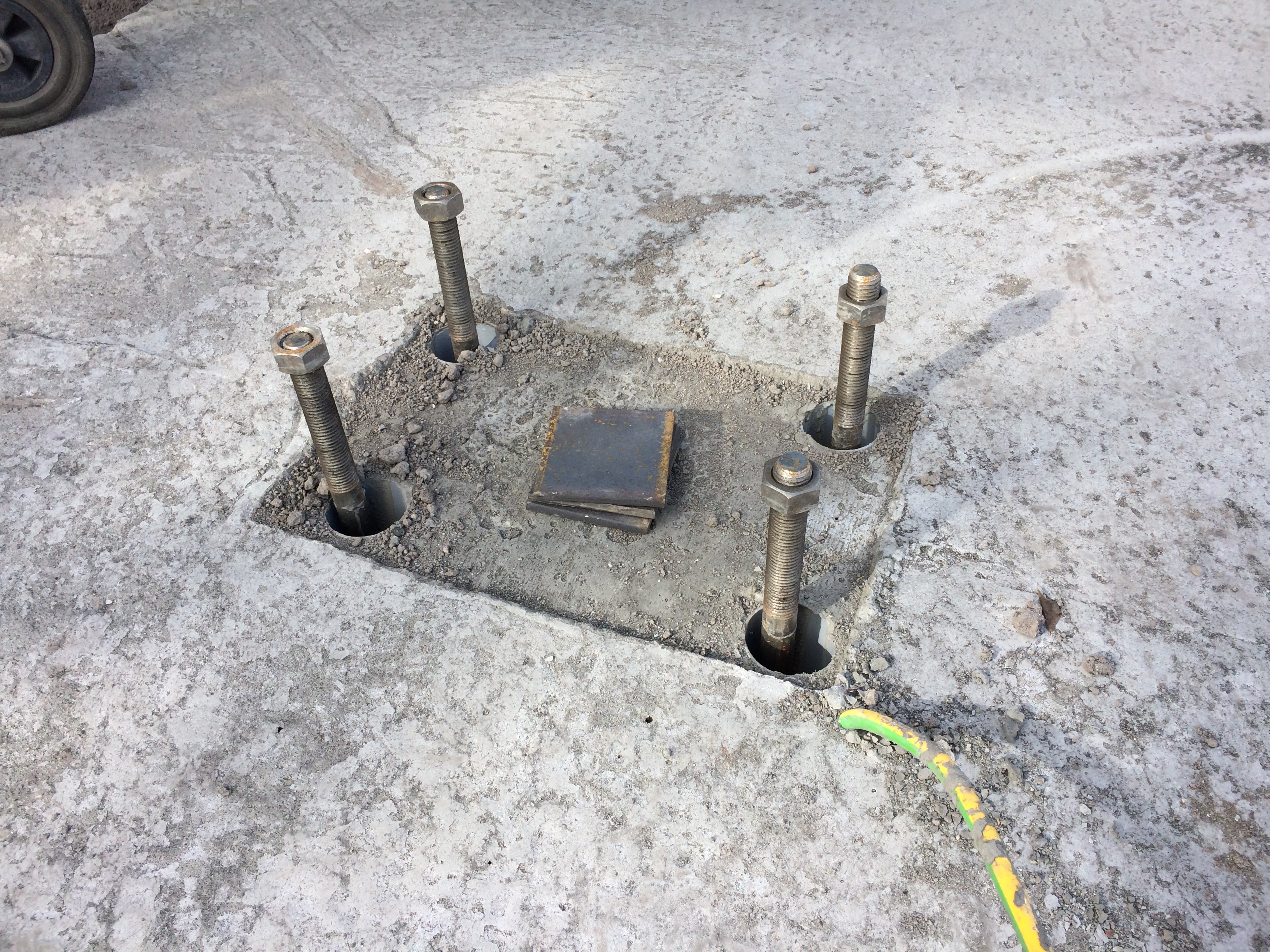
These were a pain to place as the steel cages had been pre-fabricated and lowered into place prior to the placement of the bolts and trying to attach the heavy steel right angle plates onto bolts through and 700mm deep into a 1000mm deep steel cage was tricky.
I set out the nails for the placement of the bolts, stringlines were used to set the correct position and wooden cross bracing was used to fix the pads to the correct height and location. On the first foundation featuring these plated pads we used the addition of steel tying wire to hold them into position. I quickly discovered this was not enough.
Issue. The specification for the C32/40 concrete used in the C620 foundations was for consistence class S3 and a max W/C ratio of 0.45 giving a target slump of between 100-150mm (-20mm, +30mm) and generally the team liked it at 150mm+ for ease of placement. On one of the initial pours where these particular plated bolt pads were used we had an arrival slump of 90mm which I said was acceptable, as per the guidelines, and instructed the team to begin pouring. Due to the plates on the pads and the stiffer concrete mix the bolt pads rotated and moved significantly causing me a real headache as we quickly reset the lines and used various levers and improvised methods to work them back into position. This was all to the continuous backdrop of ‘I told you it was too stiff’ from the concrete team. Thanks.
Solution. For subsequent pours I held the lorry until the slump test was conducted, used a Graham Construction slump adjustment chart to get the predicted slump to around 150mm, tested it again (if there was enough time) and poured with much greater success. In addition I insisted that steel Z bars were used to brace the bottom of the plates to the top of the steel cage and they were quickly tacked into place by the welder. This resulted in a much smoother pour and significantly less stress/abuse for me.
Reflection. The reflection from this issue was one of quality control and the difficulties surrounding it. Enforcing it has made me unpopular on a number of occasions. This site is over 18months through the project and the team of sub-contractors have been together since the start, working with LaFarge the concrete suppliers. ESG are sub contracted to conduct a slump test on all loads and 1 cube test per day or every 10 lorry loads however it has become site practice to get the cubes done every 20m3 (approx. 3-4 lorry loads). I have witnessed poor practice on a number of occasions across the site as a lorry would turn up, the slump and cubes would be taken and then the mix would be wetted up to suit the pourers and placed. On my section, to prevent this, I would have to physically stop the wagon, insist on the slump being taken, adjust the mix as required, slump test it again and then get the cubes taken. As long as I kept it within the guidelines stated above, which at the upper end was more than workable enough for the concrete team, I could not understand their reluctance to do the right thing? Quality control and assurance are vital in this a marine environment and I could only put it down to the additional time (probably no more than 10mins) it took to complete as they just want to ‘get it done’ as the subcontractor is paid per m3 of concrete poured.
There were obviously more learning points and issues that I have captured for my DO’s but having discussed responsibility, speed and accuracy, services, piling problems and solutions, more piling problems, construction methodology, ground investigation, risk, concreting and quality control I feel I can put C620 to bed for the blogs and save some final bits for AER2.
I will now start drafting a blog for another issue I already have for my retaining wall!
