Archive
Hobnobs and concrete
I’ve spent the last couple of weeks bouncing between office based negotiations to continue to try and get the Danville flood protection project off the ground and the HQ site. The former continues to be frustrating; I have spent many hours checking through submittals for USACE approval from the contractor for lift plans, labour training, concrete mix designs, schedules etc – the majority of which I have rejected as they just don’t meet the USACE construction specifications or our Health and Safety requirements manual…frustrating when they have the same documentation that I do to work through and cross-check! They are either trying to cut corners at every opportunity or are still trying to get their heads around defence contractual requirements and rigidity (this is their 1st) – I am optimistic and think it’s the latter, but having seen some of their method errors I am starting to worry about their ability. Work plans to start 7 July, and end Dec.
The HQ site is starting to look remarkably different now that pre-cast curtains are being installed. In a non-official manner I have been assisting the QC team as the QA inspections tend to be purely the final product which quite rightly contain few issues so I am learning far more hitting issues immediately after or during construction alongside the QC team – this has actually made the QA inspections even smoother, plus having a uniformed guy, with a British accent and a USACE hard-hat emblazoned with safety control logos tends to create confusion in the ranks of hard-nosed tobacco-spitting sub-contractors resulting in less-arguments. Despite being ‘qualified’ inspectors, it is interesting how little structural knowledge they have, and I impress myself at explaining to them why rebar is placed where it is as they ever keen to learn as well. I have noted that the QC has a non-purposeful habit of swaying towards areas that the QA inspects the most – for example QC checks on rebar prior to a concrete pour tends to focus on cleanliness of the deck surface and rebar ties, rather than what I’ve continually brought out – ensuring drawings are abided by (and rectified if needed!), spacings are correct and dealt with correctly around vertical conduit, and rebar has the correct clearance vertically and horizontally.
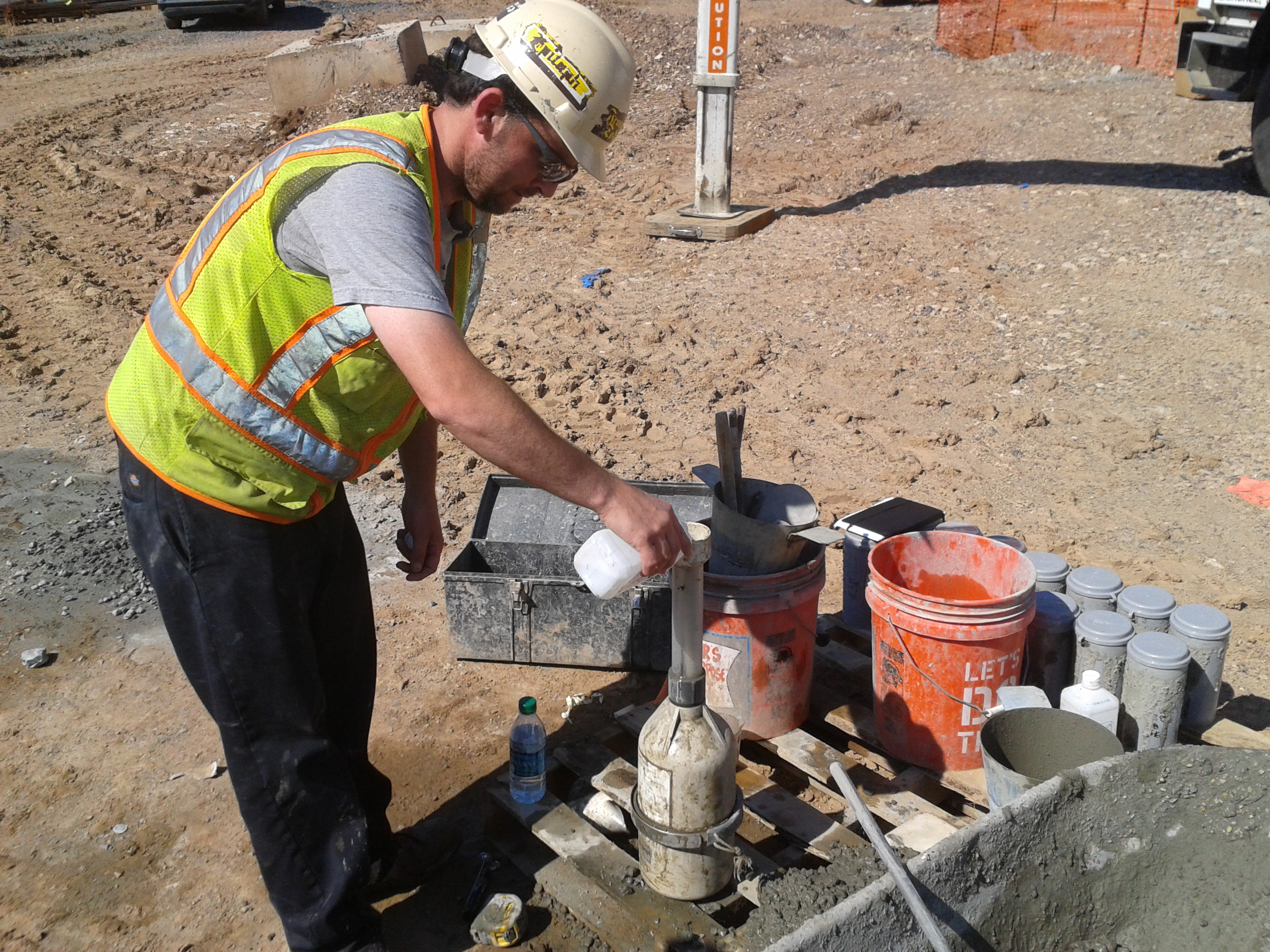
Conscious the blog is a means of sharing in order to educate, rather than just a site-diary I thought some may be interested in some of the testing methods and concrete I am involved in. Deck concrete has to be pumped to three floors high so we’ve used air-entrained, lightweight concrete. This has used pumice as the aggregate – a featherweight volcanic porous rock. Slump tests have been done, as standard, on every 2nd truck, aiming for a slump of 180mm- 230mm, making it very easy to work with. 28 day tests have given a strength of 52000kN/m2, when all that’s desired is 27600kN.m2 – this has consistently been the case! The second on-site test we’ve been doing is to measure the amount of air-voids as it’s air entrained – the specs require 5-7%. Air entrainment tests take one of three forms:
1. Pressure testing: using a pressure device, you measure the air content of fresh concrete based on the pressure-to-volume relationship of Boyles Law. Pressure is applied to the sample to compress the entrained air in the pores, then measures the change in air volume to detremine the air content. We couldn’t use this due to having porous aggregate.
2. The volumetric method or roll method (pictured below). Relying on an instrument with an in-built gauge, it is filled with fresh concrete and agitated with an excess of prescribed water and alcohol.
3. Air Indicator Kit: This kit provides a quick and easy method to check air content. A sample is placed in a vial and alcohol is added to free the air. The change in level of the alcohol in the vial stem indicates the air content.
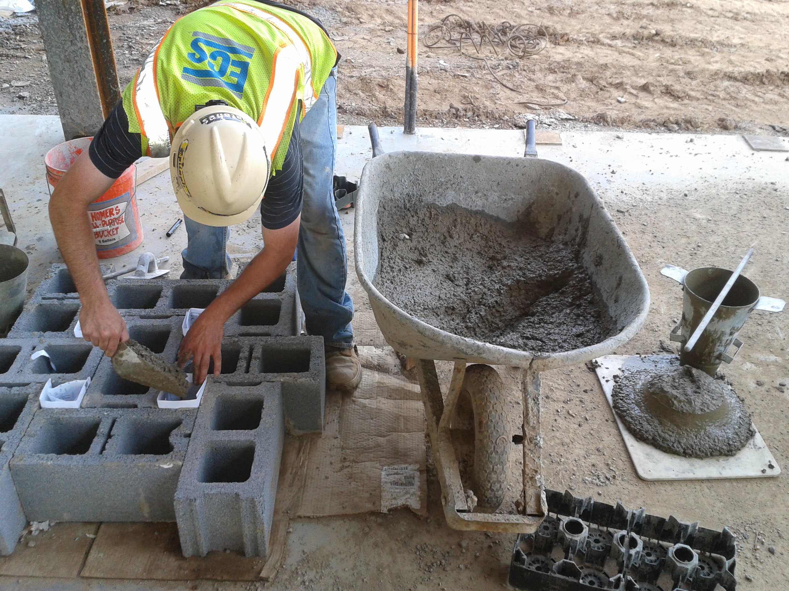
I have also been conducting grout testing for the stairwell masonry – this has involved the rather non-tech grout block testing pictured below. The paper enables a cube to be moulded whilst also allowing a transfer of water out of the grout to simulate the grout in-situ where the bricks absorb some of the water with cementitious materials in solution. We are still awaiting test results but we require 20500kN/m2; slumps 200-280mm.
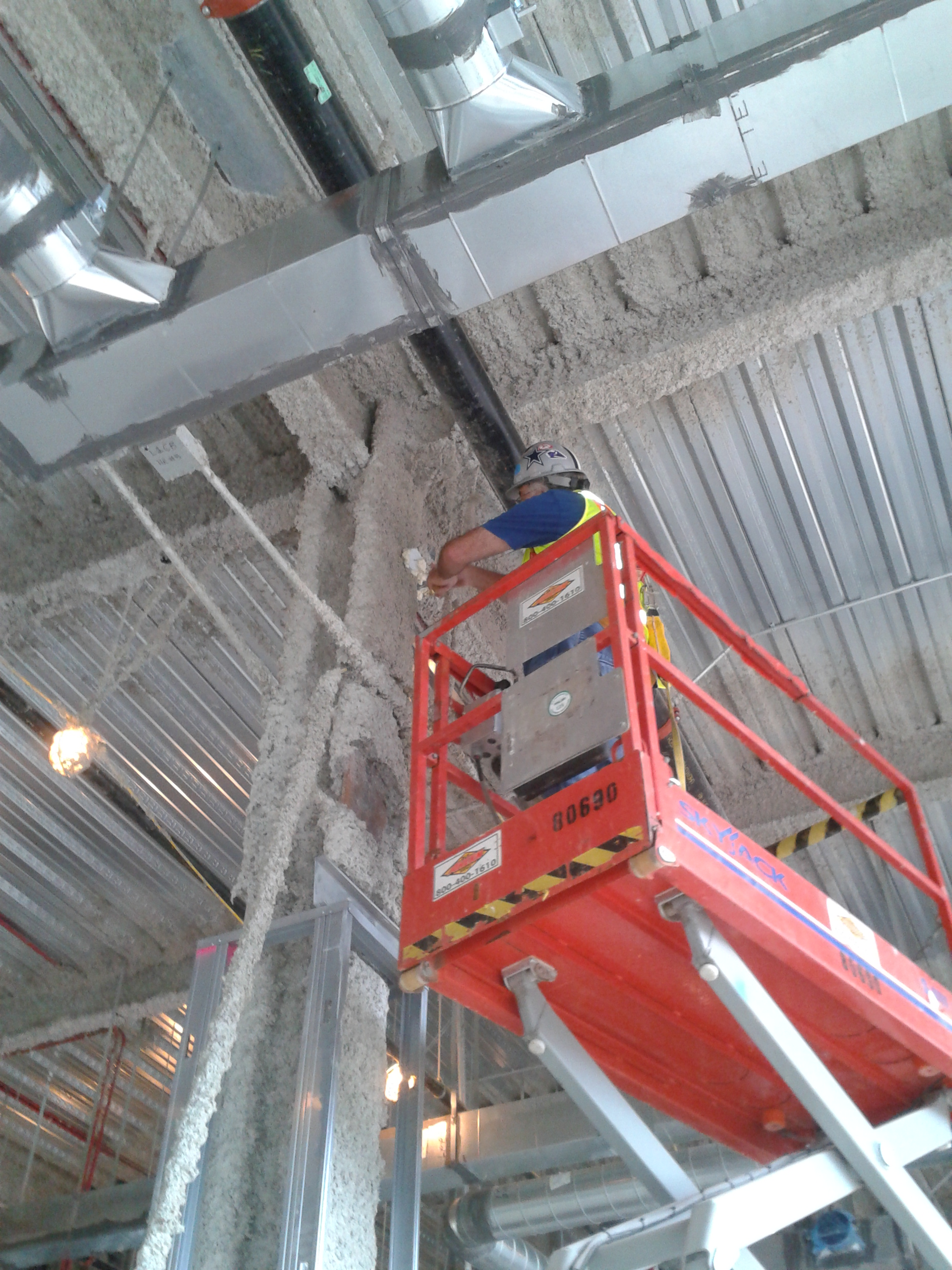
30 days post steel beam fireproofing we’ve jumped onto testing them for density and adhesion. Again, a very crude method but clearly laid out in the ASTM (EC equiv). The density test is done with a 12×9 inch removed area and lab-tested, while the adhesion test is done as follows: a mason jar-like cap with a hook is mastick’d onto random vertical and horizontal areas. After 24hrs of setting, the hook is pulled. In our case with a 1,75 inch thick material it must withstand at least 12psi of pull, unfortunately the material itself broke apart with a mere 5psi….oh dear! This has quickly shot up the pay-grades and we await a plan forward and response from the fireproofing manufacturers!
On a side, I made the most of being able to jump on the back of the District Commander’s diary so tagged along for some hobnobbing with a US Congressman who wanted to see the USACE island restoration project in the middle of Chesapeake Bay – Poplar Island. I was blown away…sustainability and PPP’s at its best…reconstituting an eroded island with rock armour and dredged material from Baltimore and Virginia ports and Chesapeake Bay that enables deep water harbours to remain open, prevents open water dumping, all whilst making a carefully balanced ecosystem haven that harbours 1000’s of terrapins and over 180 species of birds acros 7km squared. 2.4million m3 are dredged each year in the areas mentioned; the island at its present perimeter can house 30 million m3 of which 19million has been used; an expansion of the island is being applied for which will enable an aditional 23million to be used.

Goodbye chapter 13……hello chapter 8.
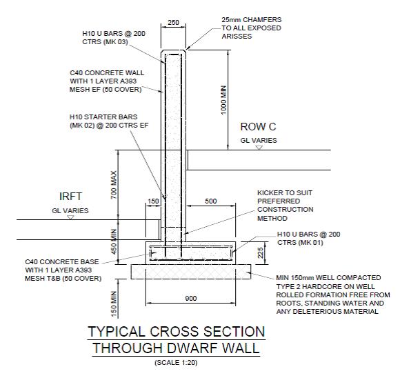
So I mentioned previously that I’m now running with the construction of a 619.310m cantilever dwarf retaining wall stretching the length of the site separating the coal storage area from the biomass handling facilities. In many ways it’s a breeze compared to the previous thrashing of the C620 foundations (hence my upsurge in blogs!) but I don’t want to tempt fate too much at this early stage.
The wall ranges in height from around 1m to over 3m with 2 distinct gradients and a varying footprint profile. The wall itself is 250mm thick, off set 500m from the edge of a 900mm long base forming a cantilever retaining wall. There are ‘Rainbirds’ positioned at regular intervals that are effectively large plinths supporting a water suppression system (to limit the dust) cast into the wall itself and contraction joints every 15m.
As it seems the assist in future discussions (thinking back to numerous piling methodology blogs) this is the construction process:
I mark out the base centre-line with the TS and off set 600mm either side allowing 100mm for a little extra space for the steel fixers to work in. Then set the height on the laser level and get the excavator in to dig to the correct level – usually about 500mm below the prepared ground surface. Compact some type 2 aggregate into the excavation and order some ST1-S3 concrete for blinding and get that in to a depth of 50mm.
I then get out the TS again and set nails in the blinding for edge of concrete at the base and the centreline of the off-set wall for the starter bars.
I’ll check the steel alignment and then order C32/40 S3 concrete and pour the 225mm base. I have been instructed not to place shuttering parallel to the direction of the wall on either side for speed and as the excavation is only 100mm extra either side the additional concrete wasted has been accepted.
As a side issue – the excavation is usually a touch bigger than 100mm either side (operator) so assume 620m of 300mm additional excavation at 225mm depth. A quick time/cost analysis of 620m of 300mm additional excavation at 225mm deep is 42m3 of wasted structural concrete at £65 a m3 = £2730. That’s 68 hours-worth of time for 2 labourers at £20 an hour to fit some reusable shuttering either side. It would take them significantly less time as it would only require single planks and minimal bracing and thus could be a small saving but I suppose it’s a drop in the ocean in the grand scheme of things. The counter argument is the time saved but I have the base slab poured at least 60m+ in advance of the much more time consuming wall construction.
Anyway, I then get out the TS again and set nails in the structural concrete base for the lines of the wall (250mm apart) and the expansion joint positions and hope that the starter bars have not moved during the base pour and appear in the correct position inside the wall makers!
The shuttering is then placed on the rear side of the wall and I use the dumpy level to put nails into the rear shuttering dictating the correct gradient for the top of the wall (1/143). This allows the joiners to place the chamfer filet. Once in place the steel fixers move in and erect the internal wall steel (just mesh) using the filet as there TOC measure to allow 50mm cover.
I then check the steel and horizontal cover prior to the front wall face shuttering being placed and second filet line positioned. Once the shuttering is complete I have been using the TS to check the top alignment of the shuttering which as long as they have used my original nails in the base and kept it vertical it has generally been within 5mm, therefore acceptable. The wall section is then poured using a 2m3 skip and crane.
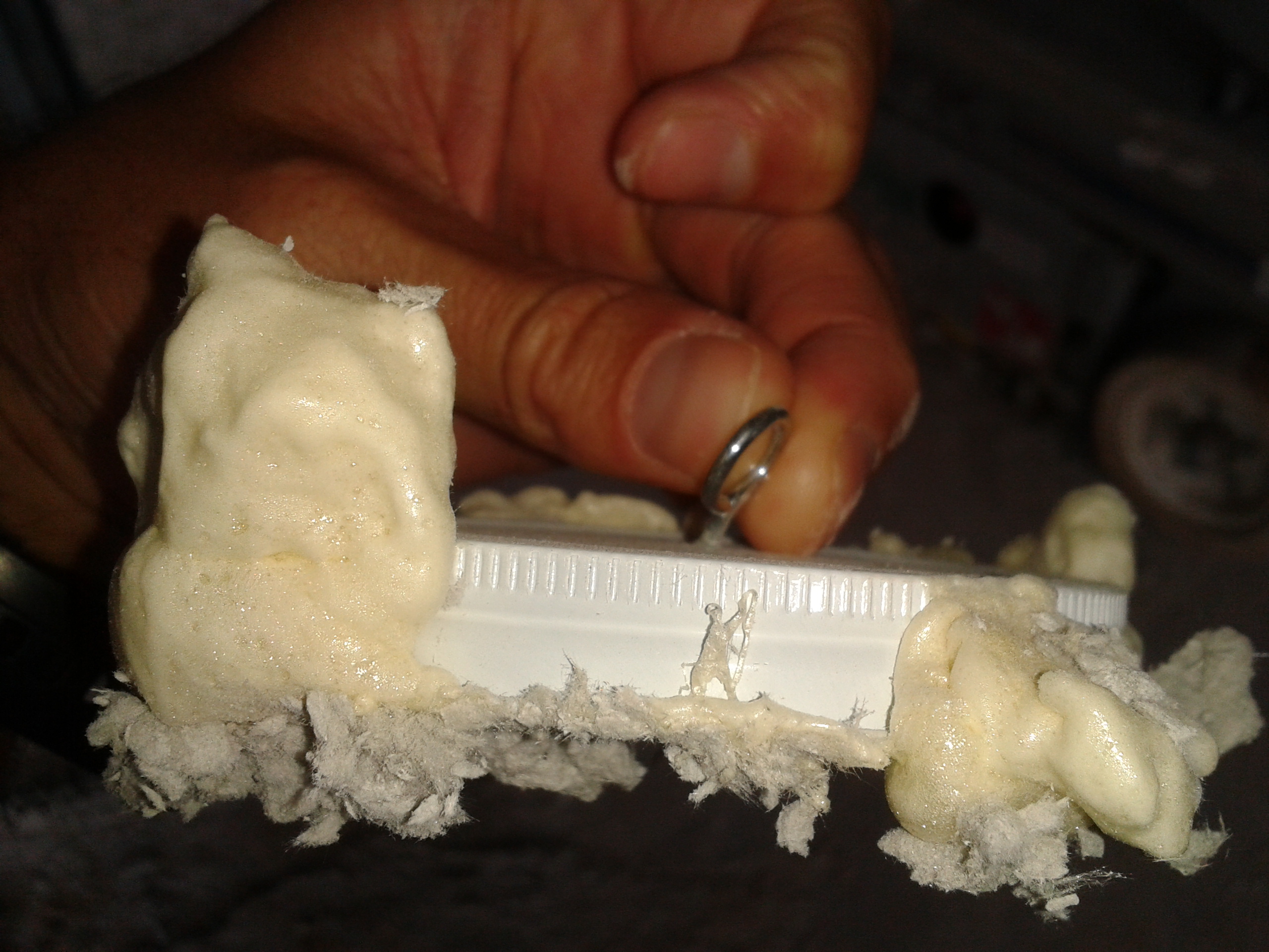
The interesting issue the wall has raised is in the contraction joint detail and there has been much discussion as to what a ‘formed day joint’ (as can be seen on the picture below) entails.
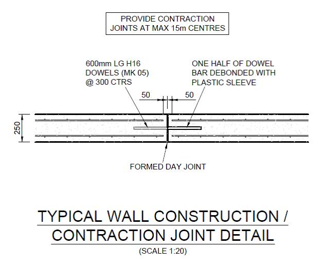
My understanding is that this is a contraction and expansion joint justified by the use of the 600mm half debonded dowels placed at 300mm centres, connecting each wall section. These are a common feature of expansion joints as the sections are tied together by these dowels but the sleeving in one of the sections allows expansion to take place without generating additional stresses within the wall. Expansion joints also feature a definitive gap between the sections to accommodate this potential movement and reduce the risk of potentially damaging forces with the structure. Clearly this gap and dowel also serve to accommodate contraction of the concrete.
To facilitate the gap of the expansion joint I have been placing 10mm sheets of flexi cell inbetween the wall sections to create the gap. These will then have 15-20mm cut away from the exposed edge and a rubber sealant will be used to waterproof the joint. The picture below shows the joint with the flexi cell prior to the sealant. This flexi cell allows contraction and expansion and increases the protection against corrosion of the steel dowels if the gap was not filled. This is the method that the joiners/fixers have used across the site for similar joints.

Questions have been asked (by other engineers) as to why I’m doing this? Their understanding of a formed day joint is simply a construction joint ie you pour up to the end of the section, allow the concrete to cure and simply pour the next section on another day from that surface. Even if a very thin divider was used to ensure clean edges this joint would surely allow only contraction and almost negligible expansion.
The GA does detail a ‘construction / contraction joint’ . A contraction joint only accommodates shrinkage so the correct procedure, by the title, is likely to not involve flexi-cell. However the use of dowel bars to accommodate contraction alone is surely a bit ‘belt and braces’ and indicates the requirement for an expansion capability?
Incidentally the concrete has contracted during the curing process, as can be seen in the flexi cell photo above. This would subsequently leave a more significant gap for future expansion if a simple construction joint was used but surely the dowel bars would be too exposed with a clear gap?
I must add that I have not been flying solo with this and checked the procedure with the MS (which mentions flexi-cell) and my line manager prior to cracking on.
Thoughts?
