Goodbye chapter 13……hello chapter 8.
So I mentioned previously that I’m now running with the construction of a 619.310m cantilever dwarf retaining wall stretching the length of the site separating the coal storage area from the biomass handling facilities. In many ways it’s a breeze compared to the previous thrashing of the C620 foundations (hence my upsurge in blogs!) but I don’t want to tempt fate too much at this early stage.
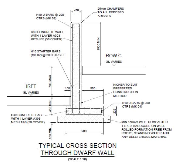
The wall ranges in height from around 1m to over 3m with 2 distinct gradients and a varying footprint profile. The wall itself is 250mm thick, off set 500m from the edge of a 900mm long base forming a cantilever retaining wall. There are ‘Rainbirds’ positioned at regular intervals that are effectively large plinths supporting a water suppression system (to limit the dust) cast into the wall itself and contraction joints every 15m.
As it seems the assist in future discussions (thinking back to numerous piling methodology blogs) this is the construction process:
I mark out the base centre-line with the TS and off set 600mm either side allowing 100mm for a little extra space for the steel fixers to work in. Then set the height on the laser level and get the excavator in to dig to the correct level – usually about 500mm below the prepared ground surface. Compact some type 2 aggregate into the excavation and order some ST1-S3 concrete for blinding and get that in to a depth of 50mm.
I then get out the TS again and set nails in the blinding for edge of concrete at the base and the centreline of the off-set wall for the starter bars.
I’ll check the steel alignment and then order C32/40 S3 concrete and pour the 225mm base. I have been instructed not to place shuttering parallel to the direction of the wall on either side for speed and as the excavation is only 100mm extra either side the additional concrete wasted has been accepted.
As a side issue – the excavation is usually a touch bigger than 100mm either side (operator) so assume 620m of 300mm additional excavation at 225mm depth. A quick time/cost analysis of 620m of 300mm additional excavation at 225mm deep is 42m3 of wasted structural concrete at £65 a m3 = £2730. That’s 68 hours-worth of time for 2 labourers at £20 an hour to fit some reusable shuttering either side. It would take them significantly less time as it would only require single planks and minimal bracing and thus could be a small saving but I suppose it’s a drop in the ocean in the grand scheme of things. The counter argument is the time saved but I have the base slab poured at least 60m+ in advance of the much more time consuming wall construction.
Anyway, I then get out the TS again and set nails in the structural concrete base for the lines of the wall (250mm apart) and the expansion joint positions and hope that the starter bars have not moved during the base pour and appear in the correct position inside the wall makers!
The shuttering is then placed on the rear side of the wall and I use the dumpy level to put nails into the rear shuttering dictating the correct gradient for the top of the wall (1/143). This allows the joiners to place the chamfer filet. Once in place the steel fixers move in and erect the internal wall steel (just mesh) using the filet as there TOC measure to allow 50mm cover.
I then check the steel and horizontal cover prior to the front wall face shuttering being placed and second filet line positioned. Once the shuttering is complete I have been using the TS to check the top alignment of the shuttering which as long as they have used my original nails in the base and kept it vertical it has generally been within 5mm, therefore acceptable. The wall section is then poured using a 2m3 skip and crane.
The interesting issue the wall has raised is in the contraction joint detail and there has been much discussion as to what a ‘formed day joint’ (as can be seen on the picture below) entails.
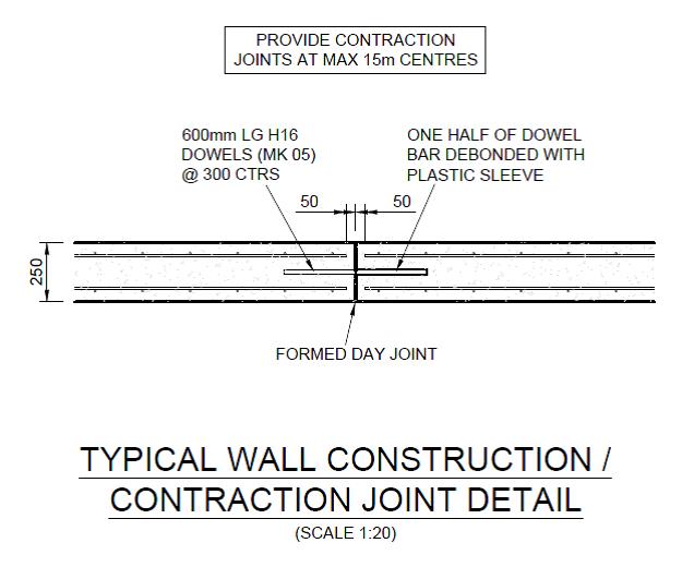
My understanding is that this is a contraction and expansion joint justified by the use of the 600mm half debonded dowels placed at 300mm centres, connecting each wall section. These are a common feature of expansion joints as the sections are tied together by these dowels but the sleeving in one of the sections allows expansion to take place without generating additional stresses within the wall. Expansion joints also feature a definitive gap between the sections to accommodate this potential movement and reduce the risk of potentially damaging forces with the structure. Clearly this gap and dowel also serve to accommodate contraction of the concrete.
To facilitate the gap of the expansion joint I have been placing 10mm sheets of flexi cell inbetween the wall sections to create the gap. These will then have 15-20mm cut away from the exposed edge and a rubber sealant will be used to waterproof the joint. The picture below shows the joint with the flexi cell prior to the sealant. This flexi cell allows contraction and expansion and increases the protection against corrosion of the steel dowels if the gap was not filled. This is the method that the joiners/fixers have used across the site for similar joints.

Questions have been asked (by other engineers) as to why I’m doing this? Their understanding of a formed day joint is simply a construction joint ie you pour up to the end of the section, allow the concrete to cure and simply pour the next section on another day from that surface. Even if a very thin divider was used to ensure clean edges this joint would surely allow only contraction and almost negligible expansion.
The GA does detail a ‘construction / contraction joint’ . A contraction joint only accommodates shrinkage so the correct procedure, by the title, is likely to not involve flexi-cell. However the use of dowel bars to accommodate contraction alone is surely a bit ‘belt and braces’ and indicates the requirement for an expansion capability?
Incidentally the concrete has contracted during the curing process, as can be seen in the flexi cell photo above. This would subsequently leave a more significant gap for future expansion if a simple construction joint was used but surely the dowel bars would be too exposed with a clear gap?
I must add that I have not been flying solo with this and checked the procedure with the MS (which mentions flexi-cell) and my line manager prior to cracking on.
Thoughts?

OK the thermal coeff of expansion for finshed concrete gives you about 5mm movement per 10 m of wall over a thermal range of 40 C ( or thereabouts)
There’s you exapnsion joint with one side of the dowel de-bonded
The day joint is just the limit of the pour – if RMC vehicles are bringing it in about 7cum per pour. Usually the reinforcement is not detailed for this so the pour finsihesd with reinforcement protruding.
Differnt strokes for different blokes
I like to have them form a dado joint by inseting a timber as part stop end. Most like the next day to water jet to roughen the joint or even etch the green concrete with etching fluid and then water clean and continue the pour.
Where the wall is water retaining I would take care on the day joints and place a water bar vertically
John, I think this may highlight the nub of the issue as a day joint, as you describe and as per the GA description, is simply a construction joint allowing continued bonding of the next section to the previous on the next day pour. This process is used elsewhere on site with the addition of a retarder on the stop end to facilitate the roughening of the joint the next day.
I do not believe that this is what is required for this wall. A day joint allows no contraction/expansion at all. The RC drawing does show 50mm end cover to the steel and not a continuation into the next section as required with a day joint and thus leads me to believe it is not the intended joint (in addition to your thermal expansion point above).
The section is poured with the flex cell held inside the end shuttering and the dowels fixed in place through it. The formwork is the shimmied along to the next section and the flexi-cell covered end of the previous section becomes the start end shuttering of the next section.
In essence for a 15m wall section, using your fag packet above, 7.5mm of expansion could be possible, therefore 10mm flexi cell should accommodate this.
I suppose the confusion exists from the terms on the drawing as a ‘day joint / construction joint’ contradicts with a ‘contraction’ joint and has led to me question what I have employed.
Joe,
Think you have the concept of day joint as opposed to movement joint sorted.
John is trying to tell you that the thermal coefficient of concrete will lead to it shirinking as it cures and cools so openning up a joint between two sections which will then allow for expansion. The size is, of course, a little difficult to guarantee because a length of wall will generally shrink inwards towards it’s mid length all things being equal (they never are) so you would see 3-5mm gap openning up at the joint. This on the assumption that the previous section was poured some time ago and has already cooled (normal). Either way, there’s enough space for the wall to warm and cool over a lesser range without issue The next aspect to bear in mind is that concrete is a wet mixed material and so dries and shrinks over it’s life (see concrete shrinkage cals…), hence the need for a contraction joint. The debonded bars act in shear to keep the wall aligned only. The wall is working structurally as a cantilever from it’s base. Weep hools along the base of the wall ensure that the contraction joints do not also perform this function and end up looking very messy, unless, of course, you want to retain water when you get into John’s descriptions of unsing hydrophyllic strips (water bar). No matter how you look at it I don’t really believe the flexi cell is required or lending anything but it will equally do no harm – probably less cost per m than the wasted concrete you discussed up top.