Archive
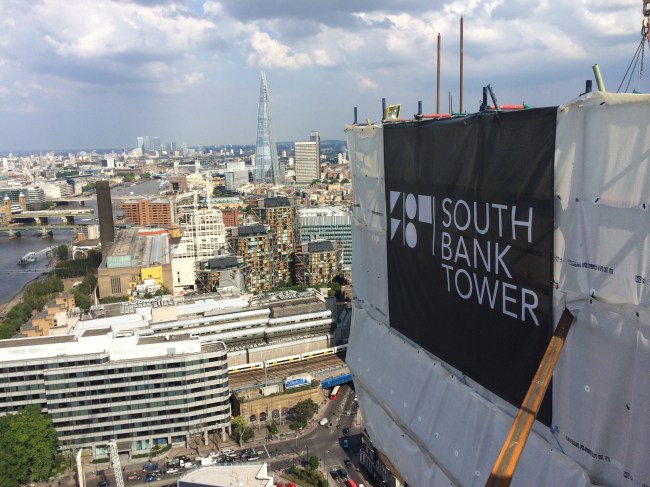
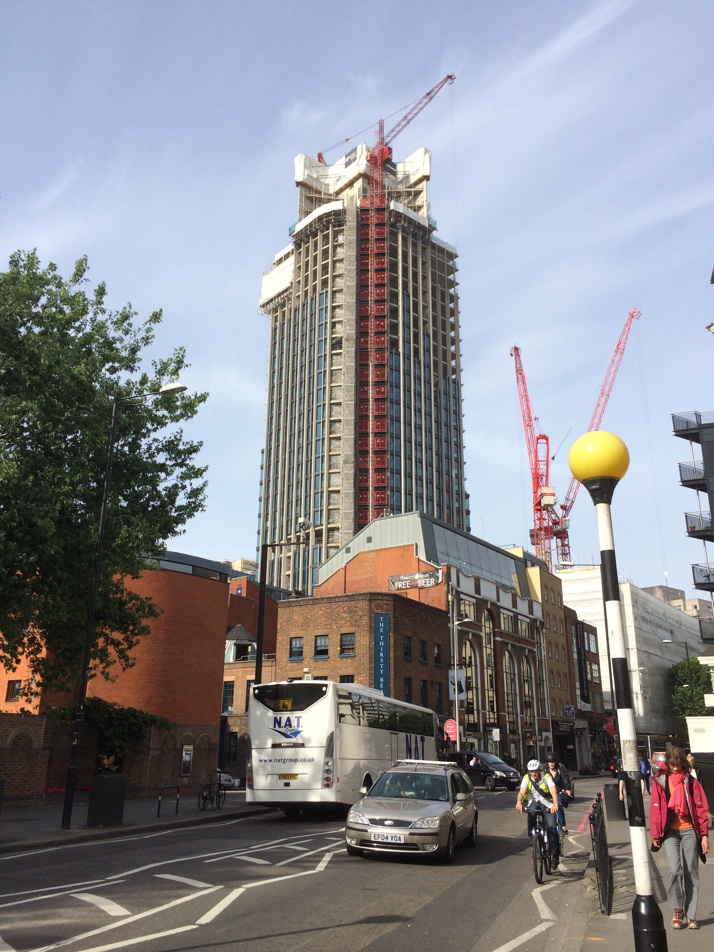
Half way to the top
The tower extension is starting to finally take shape. After a few somewhat stressful weeks getting our sub-contractors temporary works together the slipform finally launched from level 30 of the old tower.
The slipform is somewhat like oil tanker destined to have a near miss with some rocks and then be broken up! Once it is going there is no stopping it easily! And at the end of it journey it becomes redundant and is ripped to bits and cast aside!
The walls of the new tower core are only 200mm thick. This has been causing issues with fitting everything into the wall. Cover, small embed plates, climbing tubes, horizontal and vertical rebar makes for a congested beam. This has meant that whenever the slipform reached a floor level the rig was stopped for two days in order to allow all the reinforcement to be fitted. This pause also allowed us to fit bracing to the wing walls that act as sails in the wind.

The narrow walls also makes it very difficult to stop embed plates from dragging up inside the slip as it is jacked up. The embedment plates allow the exterior steel beams to be connected, with a welded fin plate, back to the core. If anyone finds themselves at a consultancy designing slipform makes the walls thickets and use 16mm vertical rebar.
Now I mentioned the near collision with the rocks and this ship. Well we, Mace, never really thought PC Harrington would deliver this tower core without fault. So surprise surprise on Friday when they informed us that two of the six corner MacAlloy embed plate pockets were in the wrong. This week we have been brainstorming to rectify this problem since there is no longer any free space to introduce the 1.5m x 2.5m embed plate into the core. See corner below.
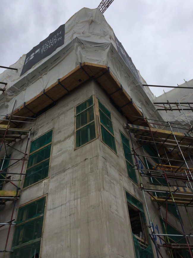
The cost to rectify this sits firmly with PC Harrington. It could, worse case, require significant temporary works to remove 1m of concrete above void such that we can get vertical rebar continuity across the embed. Best case, we can locally break out the wall to get the embed in, but the the vertical rebar won’t tie, which I’m guessing the structural engineers won’t be happy with.
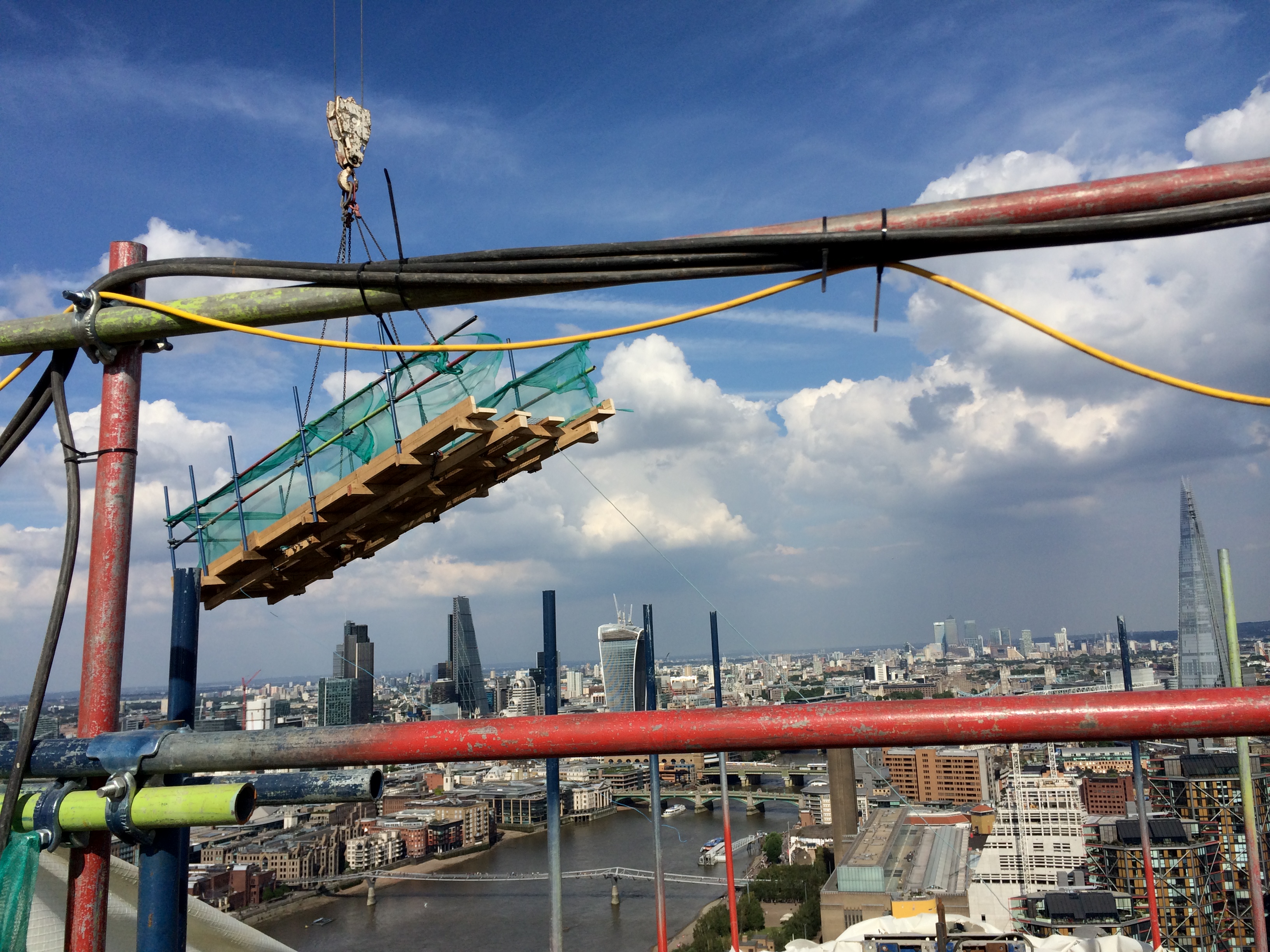
The slipform is now at the 35th SSL level which is where the four outrigger (wing) walls terminate. Therefore the rig has to be temporarily dismantled in order to allow it to continue to level 42.
Here is a picture of the top deck being lifted off. Tomorrow we will be lifting off the working deck and hanging deck together. It is a pretty precious operation since most of the lateral restraint of the slipform has to be cut to lift it down to ground.
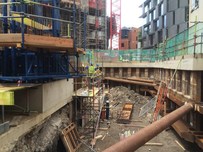
Elsewhere in the project our North Basement excavation is progressing (very slowly). The second waler is now being installed. This retaining wall is along a party wall and deflections must be limited to 10mm. Therefore the propping is very heavy. It has been on my list if ‘interesting TMR’ subjects to study sometime, but time seems to overtake!!
The focus of the project as a whole has developed too in the last two weeks. Whereas we were on a reimbursement style Construction Management Contract with the client, since there was so much outstanding design information at the start of the project, Mace have now signed a fixed price for the rest of the project. It is somewhere in the region of £200 million. However in order to make any money Mace need to accelerate the programme, and this means any major temporary works constraints made are now trying to be changed. It also means all the risk is with us (ground and all). Any sums not considered in the fixed price conversion are our of our profit. Therefore the incentive to find cost savings have significantly increased and the management of risk better managed. I’m currently working in the design of a fifth tie for the the main tower crane. This was never considered so finding a cost effective solution could be interesting.
Come back Mike Burton…all is forgiven!
I am very proud to say that I am following in the footsteps of Mike Burton. I don’t mean drinking too many ‘Quad Vods’ at Jester’s nightclub, telling war stories to impressionable students…I mean in making my mark CrossRail’s Fisher St shaft. Good to finally be on site full time…
Overview
The Fisher St project consists of two distinct sections of works;
Phase 1 was the excavation of a large access and maintenance shaft, 25m in depth running from ground level to running tunnel. Adits on the northern and southern sections of the shaft adjoin the east bound and west bound running tunnels. Mike saw this section of works completed throughout his time here. Its function during concstruction is to act as access and egress for equipment (including the removal of 2x1000tonnes tunnel boring machines), material, spoil and personnel aswell as a mean of escape. In operation it will act as a maintenance shaft and proivide ventilation to the running tunnels
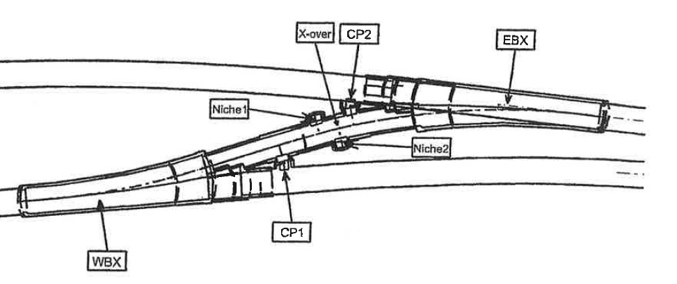
Phase 2 is the construction of the cross over section. The only point throughout the 42km of line that the two tunnels interact, the section will be used for train maintenance, in the event of a breakdown, in order to clear the line. Work is underway to excavate the ‘binocular sections’…essentially the section on each running tunnel where the tunnel divides in two to form the crossover section. My part of ship from here on in…see the overarching plan for the picture to paint my 1000 words.
Ground
I remember the Great Orator mentioning that the ground is actually quite fundamental….he mentioned it once or twice. The nature and engineering behaviour of the ground in tunneling is obviously critical to the design considerations of the underground structures. Crossrail tunnels have been bored at an average depth of 25m along their length, with the odd fluctuation to avoid existing underground structures. The tunnel boring machines and station tunnels and caverns have been bored/dug with relative ease due to the excavations being conducted largely in the London Clay Group. Having looked at some of the ground investigation data, it seems that this consists of stiff or silty clay ranging right through to mudstone. These Palaeogene marine deposits, I’ve been assured, make for an excellent tunnelling medium, due to their relative homogeneity offering some predictability, and their short term stiffness, which allows brief unloading without collapse, ahead of stabilisation with SCL.
However, in the Fisher St/Farringdon area, the base of the London Clay sits at approximately 30m below Ordanance Datum. This area coincides with a ‘busy’ underground infrastructure network (proximity of Central and Piccadilly Lines, aswell as numerous underground services) which constrains the allignment depth. You will see from the Geological section above that just at the point of constructing arguably the most complex section of works in the allignment, we pitch head first in to the Lambeth Group.
At this stage, its probably worth thinking back to the days of the McGuirk Bluffing Face…a slight nod of recognition toward said lecturer as if I was following, when internally I was in a flat spin. Well, the same thing happened when I was told this; as if I understood immediately the implications of it…I didn’t. So I did some reading!! Yea alright, stop laughing….
This is what I learnt….we’re predominantly in the red/brown or green/grey ‘Upper Mottled Beds’, but there is quite a bit of other stuff (technical term); from fine silty sands, shell beds and sandy flint. Bottom line, its a bit of a mess; in contrast to the relative homogeneity of the London Clay belt, this material is vertically and horizontally inconsistent. For tunneling, this presents risks; potentially water bearing, the excavations could cause a flow of material along failure planes as they are uncovered, major face instability prior to concrete spraying, and greater than expected surface settlement with associated damage to surface structures in prime central London real estate.
The Tunnel Boring Machines have passed through the allignment, without reported incident, and as such I have had a few raised eyebrows for asking what the perceived risks are in relation to our excavation. This would be ok…but I since discovered that the TBM has no means of recording the nature of the ground that it passes through, for its properties, contamination or indeed the ground water regime. So essentially, we’re operating solely on a triangulation of two boreholes located 30m and 20m distant from our crossover section, and a baseline statement in the Geotechnical Baseline Report that the lower aquifer on our location is approximately 30m below the excavtion and is therefore of no significance.
Groundwater
I think that the proximity of the borehole data gives us a fair idea of thewhat the enlargement excavation will uncover, so the primary risk will be in the groundwater regime. We are aware that the Lambeth Group is likely to bear isolated pockets of water; so the water is anticipated but the quantity is unknown. So this leads to a number of risks, (based entirely on ripping off Johns notes…)
- Potential for inundation into the tunnel as a pocket of water is uncovered.
- The Lambeth Group is non-cohesive, so this may lead to an increased risk of heave in the tunnel invert if the resistance to this uplift is less than the head created by this water
- Instability in the face due to ground movements caused by pore water pressure.
I must admit, I’m not yet sure what we’re doing about this, if anything, and so I will revisit in future blogs….
What next?
A part of the Phase 2 works, the binocular section on the westbound tunnel (WBX) has been excavated and the primary lining sprayed.
The construction of the cast in situ secondary lining works will now go ahead, with me firmly installed as the section engineer! Blog to follow….
