Archive
Risk Assessments
Risk.
Asked to conduct a survey of a capping beam i looked to install a suitable access via a ladder and then use a harness to secure myself to the outside edge of the capping beam. At this point I was told that this was considered dangerous and that should Crossrail spot me i would be asked to leave site. The Junior engineer told me that we should wait until Saturday when it would be quiet and no one would see me accessing the capping beam. I entered a short argument during which I pointed out. The survey would take a maximum of 5 mins and that the two approaches that the other site engineers wanted to take were wrong.

View of capping beam. Survey required of right edge, acces via broken ground behind orange pipe next to exposed scafold bars
The Options
Overly Safe. The option considered safe was to construct a scaffold tower access to the capping beam area. To which i pointed out:
1. It would take longer to construct the scaffold platform then it would take to conduct the survey
2. The risk that the scaffolders would be exposed too during the construction of the platform were the same as those that I would be exposed to during my survey. However they would be exposed to them for longer, thus increasing the risk.
Unsafe Option. The preferred option by the other engineers was to turn a blind eye and then climb onto the capping beam at the weekend without a RA. This I pointed out was possibly worse. This showed no planning of the task at hand no consideration of the risk and how to mitigate against them.
My solution seemed to be breaking new boundaries of risk acceptance and planning. I simple planned to secure a ladder to the bottom of the capping beam and midway using scaffold bars, thus preventing it from moving and then to wear a work restraint harness to prevent me from working to close to the edge. Risk assessment filled out i then presented my case to the project manager and won the argument. Survey completed and i am still alive to write this rather dull blog.
However the point I later made to my project manager is one that I have made time and time again. The aversion to risk causes engineers and operatives on site to take greater risks without proper planning. The requirement for engineers to write task sheets and method statements for all tasks on site means they are constrained by unnecessary paperwork. Having written a task sheet and risk assessment they then brief the operatives, but then fail to ask question 4 once on site ‘has the situation changed?’. To which can always be answered yes!. Task sheets and risk assessments are never updated and in effect the engineers are then working illegally, should there be an accident the RA would be void and there would be no evidence of a RA to cover the works at the time of the accident despite all the paper work that had gone before.
Has anyone else had issues like this???
Block G Catastophe
Well I escaped the responsibility of Block G as there is still plenty of work to with ensuring that everything gets completed as OIC sewers, water and power. But I thought I would blog about this event from a few weeks ago especially for John and the Phase 1s as this is the part of the cofferdam they might be visiting.
Background
Block G is the most southern section of the building about 25m from the SW corner of the power station. On the thinnest part of land between the building and the railway arches. It is also the deepest part of the basement with the excavation due to be taken down to 8m BGL.
 Block G (Power Station is to the top-left (25m) and railway structure below the drawing (10m))
Problem
As the dig was progressing the banksman noticed a hole in the sheet about 200mm by 200-250mm located at around -2.3m to -2.5m AOD (Ground level is +3.5m AOD). The hole seemed to have had a plate welded over it but the plate had come off. With the ground water level at around 0m AOD so some water was coming in and we had a bit of a puddle forming at the bottom corner.

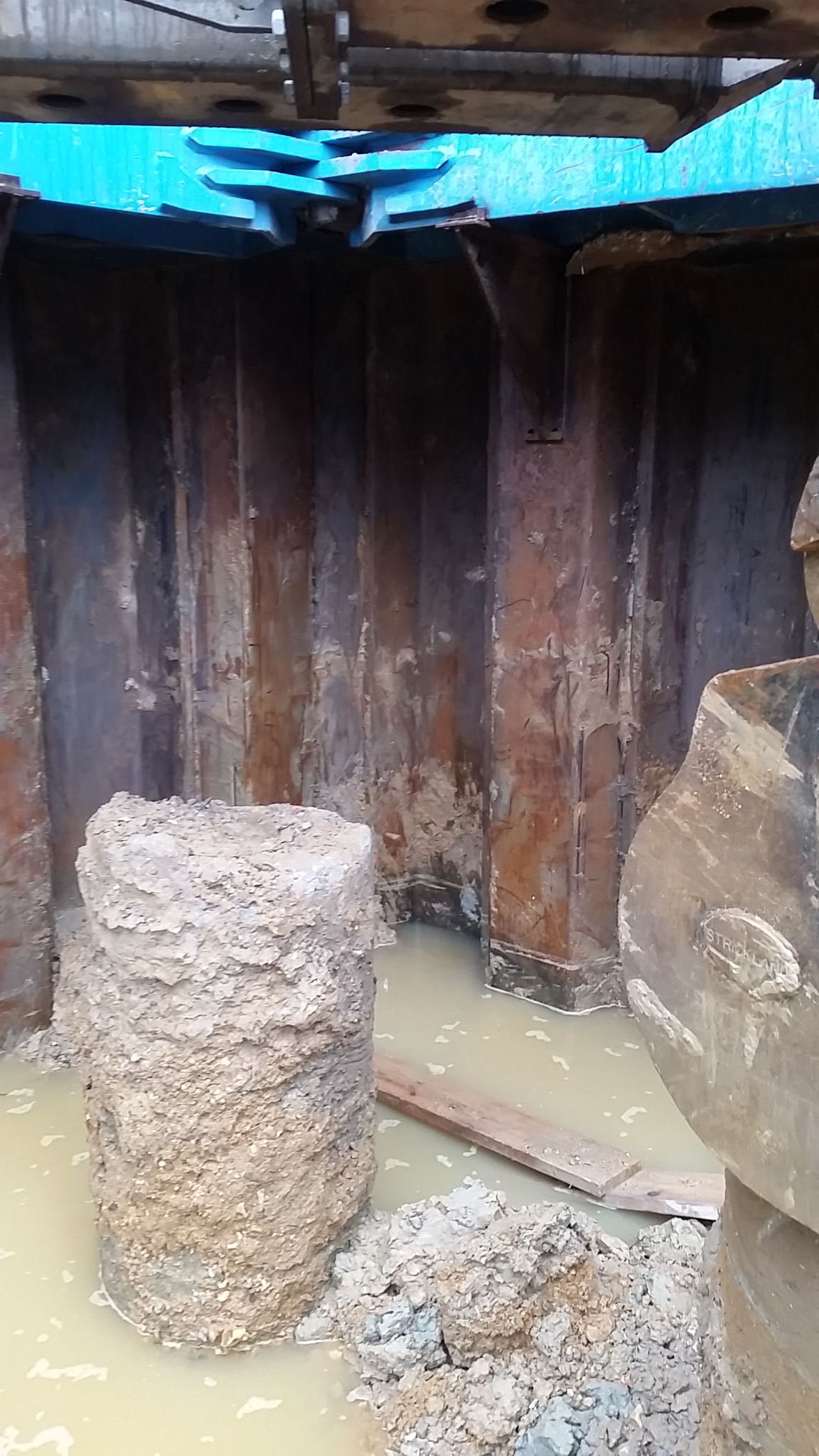
Initially that morning all were very calm, just a bit annoyed that there was a hole in the sheet pile. Apparently the hole had been noticed over the weekend but it wasn’t until the rain on Bank Holiday Monday that the water had risen to 1m high. THe construction staff in the office started to fly a few ideas around about how to seal the hole but with unstable sandy gravels and some clay in the excavation is wasn’t a safe enough surface to work from.
By 1600 hours after more rain things got more interesting and a nice pond feature started to appear:


The excavators had retreated to the highest points they could but the water had risen nearly 1.5m and was now lapping around their tracks. The office then became much more excited and frantic emails were being sent backwards and forwards between the construction manager and the temporary works department. The de-watering well can be seen in the pictures as the blue vertical pipe and this was maintaining the water level but not draining it. They tried to pump the water out with 2 tankers but the high groundwater levels in the terrace gravels above the clay layer just kept coming in. They then noticed another problem hiding behind the sheet piles:
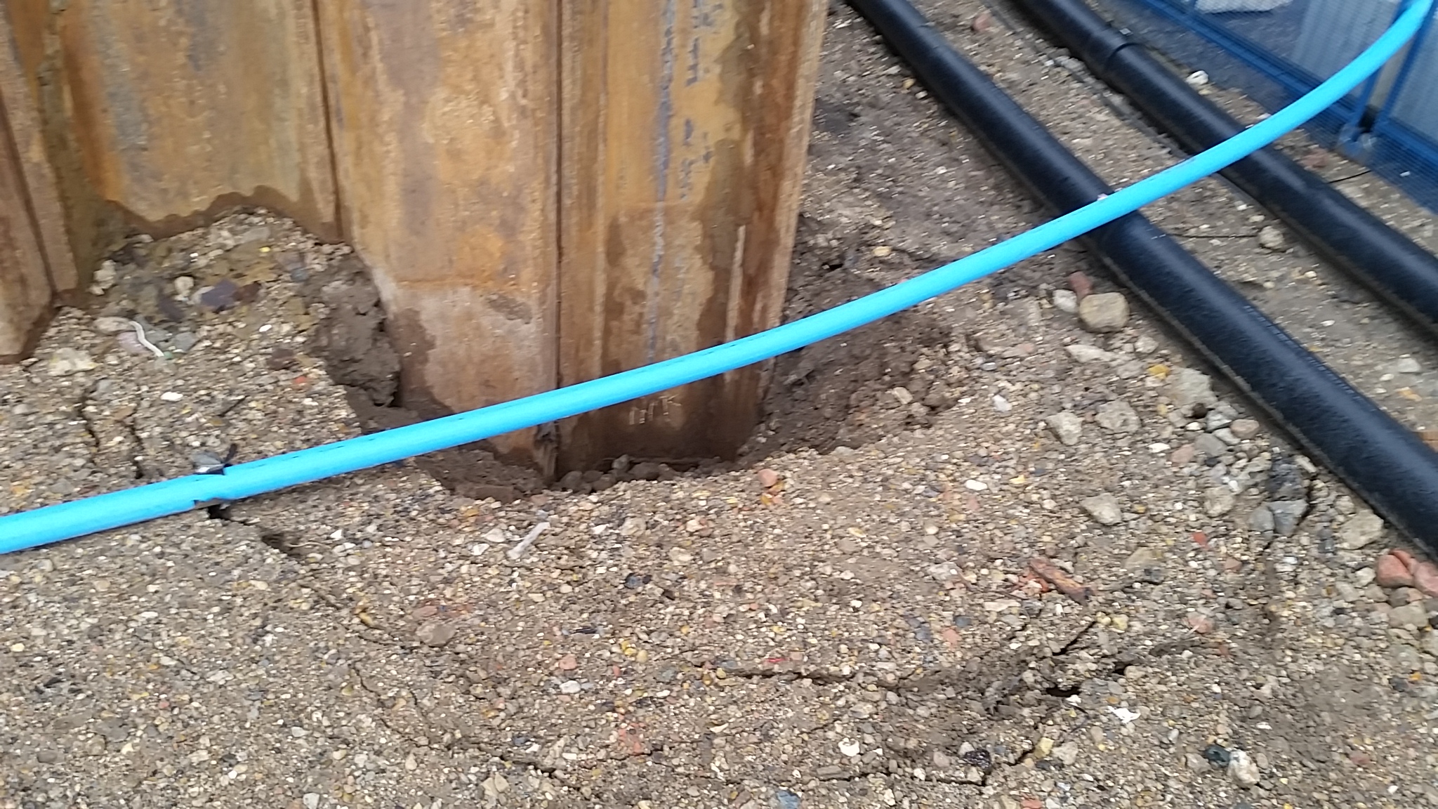
The constant pumping and removal of the water was also washing the fines into the hole creating voids causing ground loss on the surface behind the sheet piles. Luckily this corner isn’t right next to the power station or the railway line!
Solutions
My input to the problem was the suggestion of whacky ideas that could actually work the best being what I learnt on the Royal Navy Damage Repair Instructional Unit:
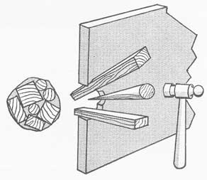
All you needed was to get the water down low enough to hammer some soft wood wedges in the hole or get a diver in! But since we couldn’t get the water levels down enough and a diver would take far too long the idea was liked in theory but not in practice.
The only other option was to block the other side of the sheet pile by driving another sheet pile behind it. All pumping was stopped to allow the water level to equalise and stop the migration of fines and they set about building a piling mat to support the crane required to drive the sheet pile into place. Once completed the water was pumped out and the culprit was uncovered and a plate was welded over the hole:

Lessons Learnt
- Don’t scrimp on second hand sheet piles at the deepest part of the excavation!
- Don’t use sheet piles with holes in or a plate welded on over the hole as they get ripped off during driving!
- If there’s a hole in your sheet pile, plug it immediately, don’t wait for it to flood over the Bank Holiday.
- Pumping water out of an excavation being fed by a months rainwater in the ground probably won’t work.
- RE Divers would have probably fixed it in a day and actually earned their dive pay.
Conclusion
Having caused a 1 week delay on the progress of Block G and incurred the cost of an additional piling mat and sheet pile being driven it will be interesting to see who foots the bill for this one. Carillion will blame the sheet pilers for using defective piles. They will blame Carillion for telling them to use second hand piles (one story is that decision was made to save money as these piles will be cut to join onto the Phase 2 works, the other story is that the job was rushed and only second hand piles were available). Someone will no doubt get the task of digging through numerous Employers Requirements (ERs), Addendum ER and Contractor Proposals to point the finger of blame.
Extra-Curricular Work
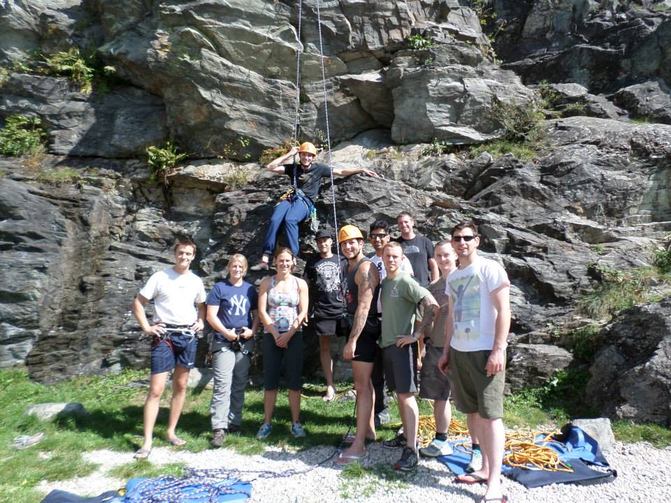
One of the reasons that Neil thought I was dead was that I have been away for a week in France teaching the AAC how to climb. I successfully delivered the new Rock Climbing Single Pitch Foundation (RSF) Course to 8 students on their expedition to a small place just outside Chamonix.

In the last month I have also become the Army Female Mountain Bike Champion and I represented the Army at the Inter-Services yesterday where I became the Inter-Services Champion. Unfortunately as a team we were beaten by the RNRM (who had set a gnarly course that looked like a B3 had got lost in the woods with a piece of mine tape!). I am hoping to race for the Army in National competitions next year and also get a nice bike sponsorship deal (and yes Rich, I am becoming a Stravasshole!).


Fixing mistakes
I’ve mentioned in a few comments there are now getting to be a number of repairs that are needed on parts of the substructure. With a bit of luck what I’ve learnt may help anyone else that ends up with similar issues in the future, or feel free to tell me where I’ve gone wrong!
Problem
They fall into 2 categories – damage after the works and incorrect procedure resulting in remedial action. There are a number of causes for both starting to happen in my opinion. Initially there was a big push to get productivity up, then there was the need to reduce costs. This started with reducing the numbers on site and we are now in the situation of reducing hours for some of the work groups. This means moving people about the site and workers jumping from one crew to another. This leads to procedures not being followed and a new learning period if the crew changes and the new bloke gets left to stay back and finish off the pour. However I digress.
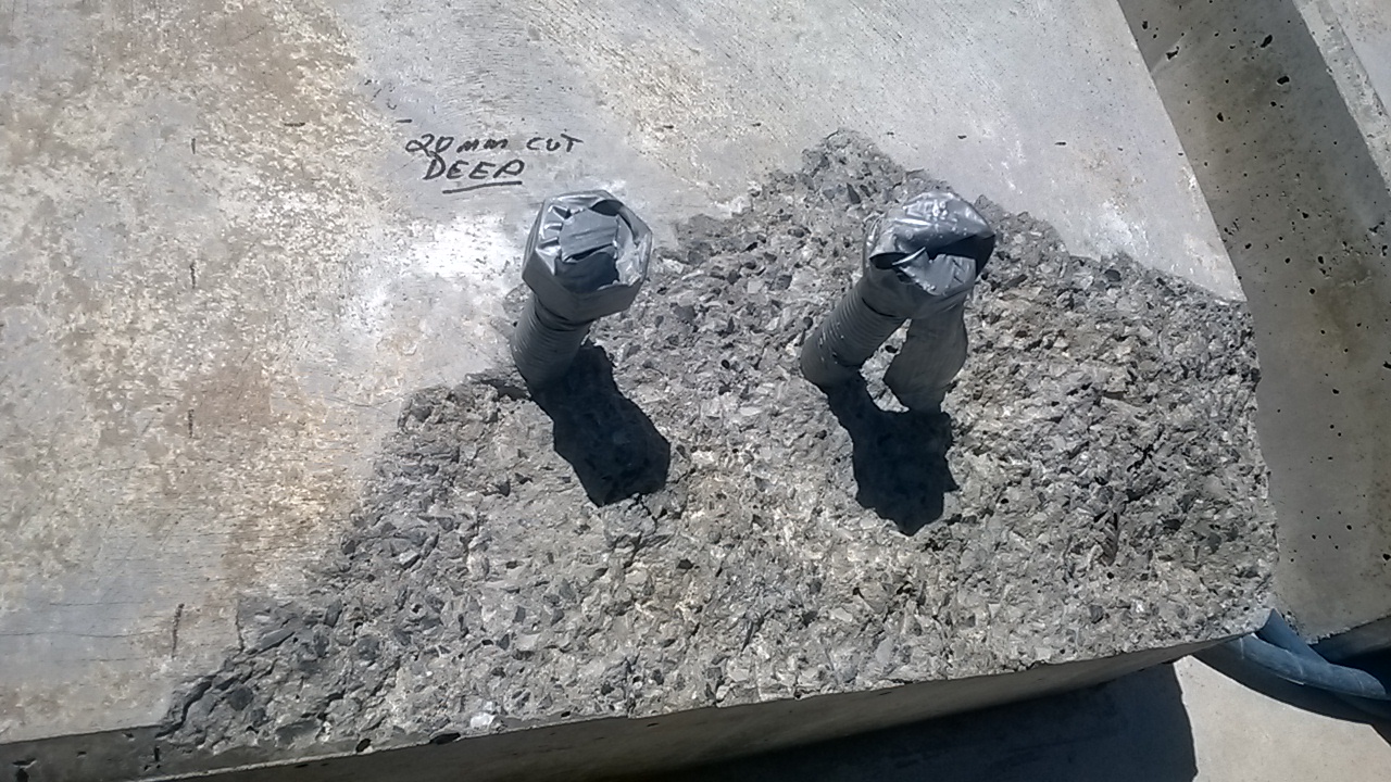
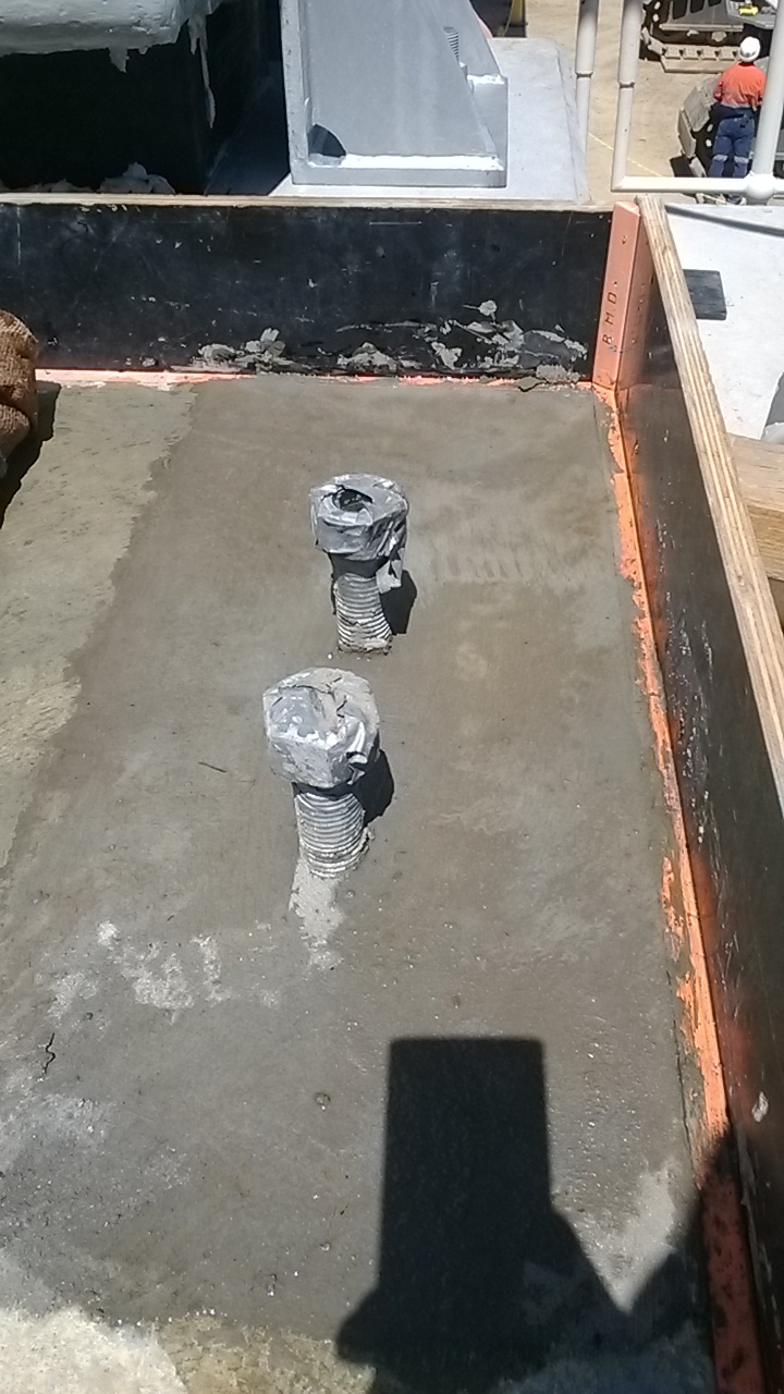
The photo below shows the damage done to one of the pedestals on pier 10. The workers that stripped the formwork said nothing about it happening, and the concrete that broke off is sound, as is the concrete remaining on the pedestal. The formwork could have been removed at an angle, or there could have been a lack of form oil on those sides. I think the most likely cause is that a sledgehammer was used to help persuade the forms off, not that anyone is owning up to that.

Solution
To fix the problem the concure had to be removed, which proved much more difficult than first thought. Most curing membranes on the approved list for transport and Main Roads degrade after a period of 6 to 8 weeks (normally under UV light). However trying to remove the membrane before this isn’t that easy. High pressure water blasting isn’t effective. There are a lot of environmental controls involved with sand blasting (not to mention the cost involved). That only leave mechanical removal, or in this case a man scrubbing it off with a scouring pad fitted to a buffer. The cost of this work now, however is preferable to doing the rework later in the program (after 6-8 weeks) as the girders will have been landed and cross girders poured. While it is still possible, the access is severely restricted and will take much longer to perform.
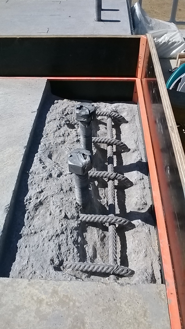
Back to the solution to the breakages. The concrete had to be cut out to a depth of 20mm and then broken out to expose the reinforcement. There needed to be sufficient room behind the bars to ensure that the aggregate flowed behind the bars and made a strong bond. See photo above for what it looked like after being formed up. After this the area was cleaned out and dampened (but no free water on the surface.The next stage was coating the steel and concrete in Nitobond AR. This is a 2 part epoxy that is designed for bonding fresh concrete to old concrete (or concrete that has already set). I did consider using other products such as Renderoc HB70, however the client preferred using a concrete patch for the aggregate component. The other side of the pedestal had no exposed reo and so a small bar of reo was chemset into the pedestal to provide a sound anchor for the new concrete. IT was a different 2 part epoxy used for this – Hiti have RE 500 which is very common, but expensive, we used Power fasteners PF PRO but there is also a chamset series of products by Ramset. The combination of the steel as an anchor and the nitobond should stop any problems of the repair falling out in the future – as due to a different batch of concrete being used there have been instances of repairs just falling out, with the differential thermal expansion of the two mixes.
The Other Problem
The issues with our own procedures not being followed have led to a different set of repairs. On the headstock the construction joints for the pedestals need to be prepared the day after the pour. To make the preparation of these joints easy we apply Rugasol (made by Sika) after the pour is finished, there are other equivalent products by Parchem, Ramset etc that could be used. Using this makes the greencutting the following day much easier and can give a very good clean construction joint. The rugasol should be worked into the area of the joint (it can be sprayed on, but this doesn’t work with the curing method we are using). If it is not worked in then when the damp hessian is placed ontop and flooded with water the Rugasol can spill out over the entire headstock. This has happened a couple of times, and while the impact isn’t dramatic it reduces the quality of finish on the surface. The inspectors have issued an NCR and stated that they want the surface dressed to achieve a class 2 finish – this is well within their rights as that is what is in the contract. They went a step further though (too far in my opinion) and have instructed us to coat the surface with Xypex Modified. This is a waterproofing sealant that is normally used in marine environments, reservoirs/dams and swimming pools. As there is no cracking or reduction in cover depth I think this is excessive, and can’t think of a reason for this being required for what was an aesthetic issue. Thankfully this is a one off problem. With more supervisors now on site the workmanship issues should disappear. (I planned to show some photos of this, but I’m on leave now and have left them back in Oz!)
Cranes alongside railways
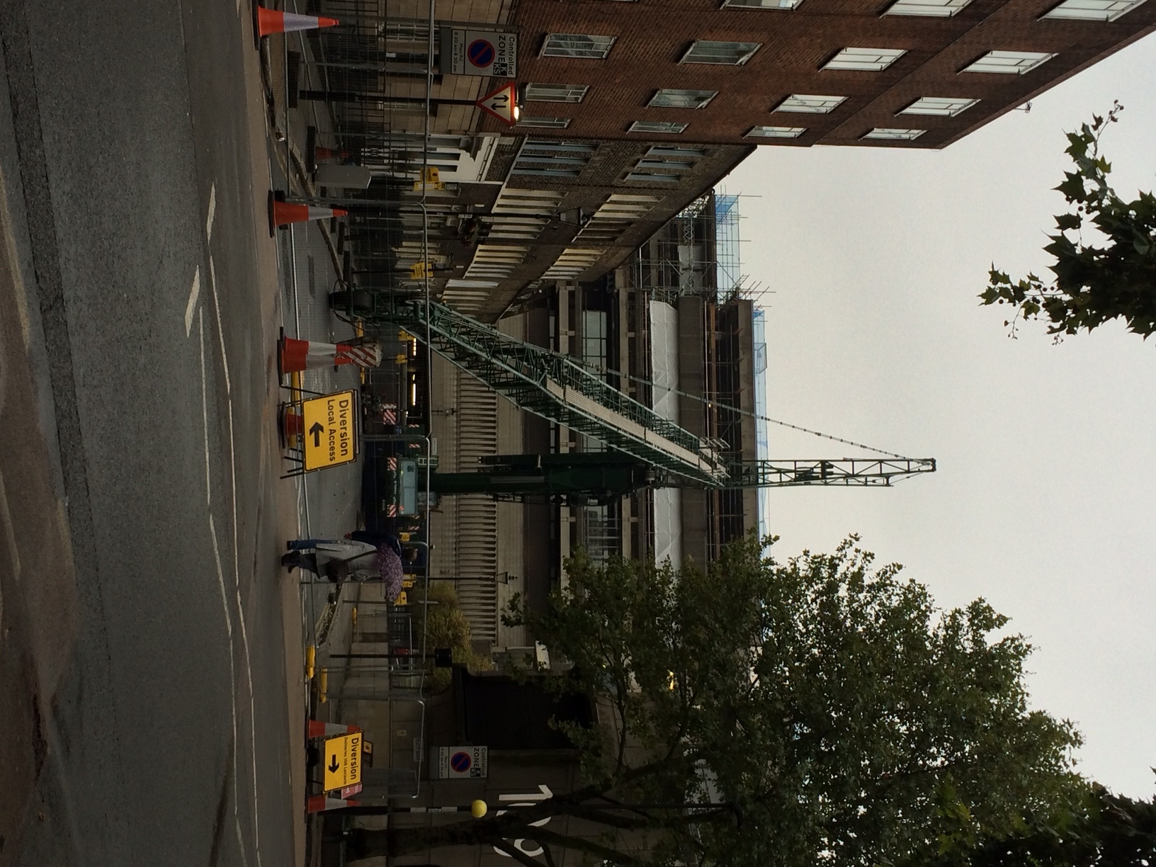
As well as my work on the South Bank Tower I am also the Construction Engineer for Mace at a small site in Lambeth, at a Metropolitan Police Station. This police station is a forensics lab, headquarters for a firearms unit and also a communications HQ for police and fire calls.
Maces scope of works is predominantly M&E. We are relocating the existing plant onto the roof of the existing five storey structure. Originally built in the early 1970s it was first used by the Royal Mail as a sorting office and as such is a very robust structure with 14 and 18inch thick floor slabs, with RC columns in approx. a 10m grid.
In order to relocate the plant onto the roof, a steelwork grillage is to be built in order to allow the high permanent dead loads to be bear directly on top of the existing RC columns, instead of the roof which obviously is not strong enough. Being London the site is particularly constricted. To the east is the rail mainline into Waterloo (the Reading line), to the south a narrow road, to the west there is no access since there is a hotel and to the north there is a small residential street used by the police for access.
The key challenge for me has been to plan how to erect a tower crane on the roof of the existing building, which will lift all the plant into its position. This needed to be achieved with limited access and immediately beside a live railway. Network Rail require anyone working beside the railway to have an agreement in place and any works which could impact the railway to be signed off by their Railway Asset Protection Team. As part of the approval process the principal contractor has to nominate a Designated Project Engineer (my role) and a Contractor Responsible Engineer (min Chartered Engineer).
Network Rail operates in a risk focused manner. They trust nobody and everything that could potentially impact the railway is scrutinised to ensure the risk has been appropriately managed. Obviously using a mobile crane to erect a tower crane on the roof of an existing building and then operating a tower crane to lift pieces of plant, up to 10 tonnes in weight, is relatively risky.
Managing the risk effectively, thereby reducing the level to an acceptable level for Network Rail, required prolonged engagement and forward planning. We had to demonstrate we had explored all alternative options and the chosen option then had to be designed and category III checked. This task was doubled with having to design and check both the mobile crane, and the tower crane.
Tower Crane Grillage
For the tower crane, in order to progress the early design of the tower crane I undertook initial design feasibility to determine the scheme was viable and also give the steel fabricator indicative sizes of beam for pricing. I then gave the detailed design and analysis of the crane grillage (utilising the permanent works steelwork) to a temporary works designer to complete. In order to verify the existing structure was adequate to support the tower crane loads, combined with plant loads, I then undertook a detailed analysis of the building.
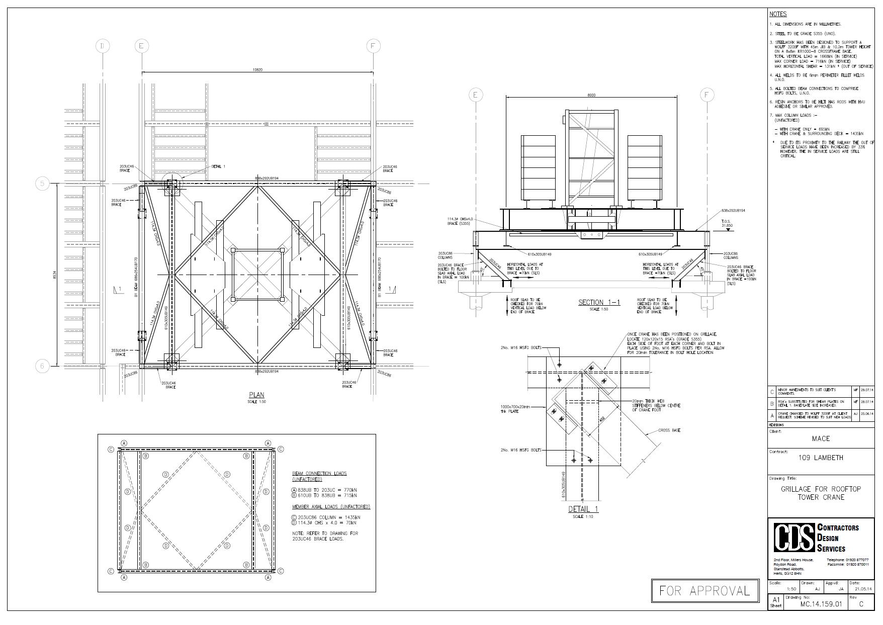
The steelwork grillage design and building verification was then category III checked by an independent engineer.
Mobile Crane
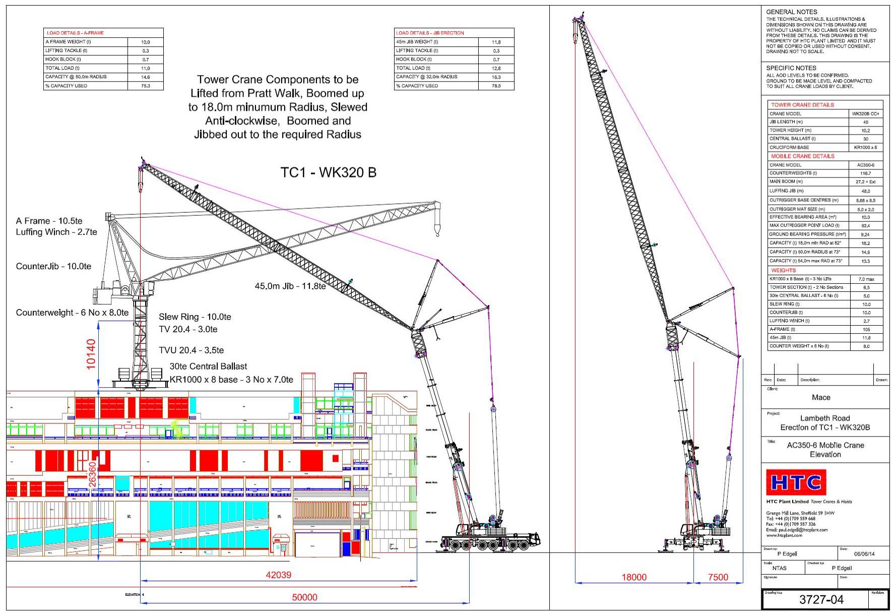
I undertook the design of the mobile crane foundations. The only workable position was for the 320 tonne mobile (a Terex AC350-6) was to situate it in Pratt Walk, an urban road between the police station and a row of occupied residential house (separating the crane and railway).
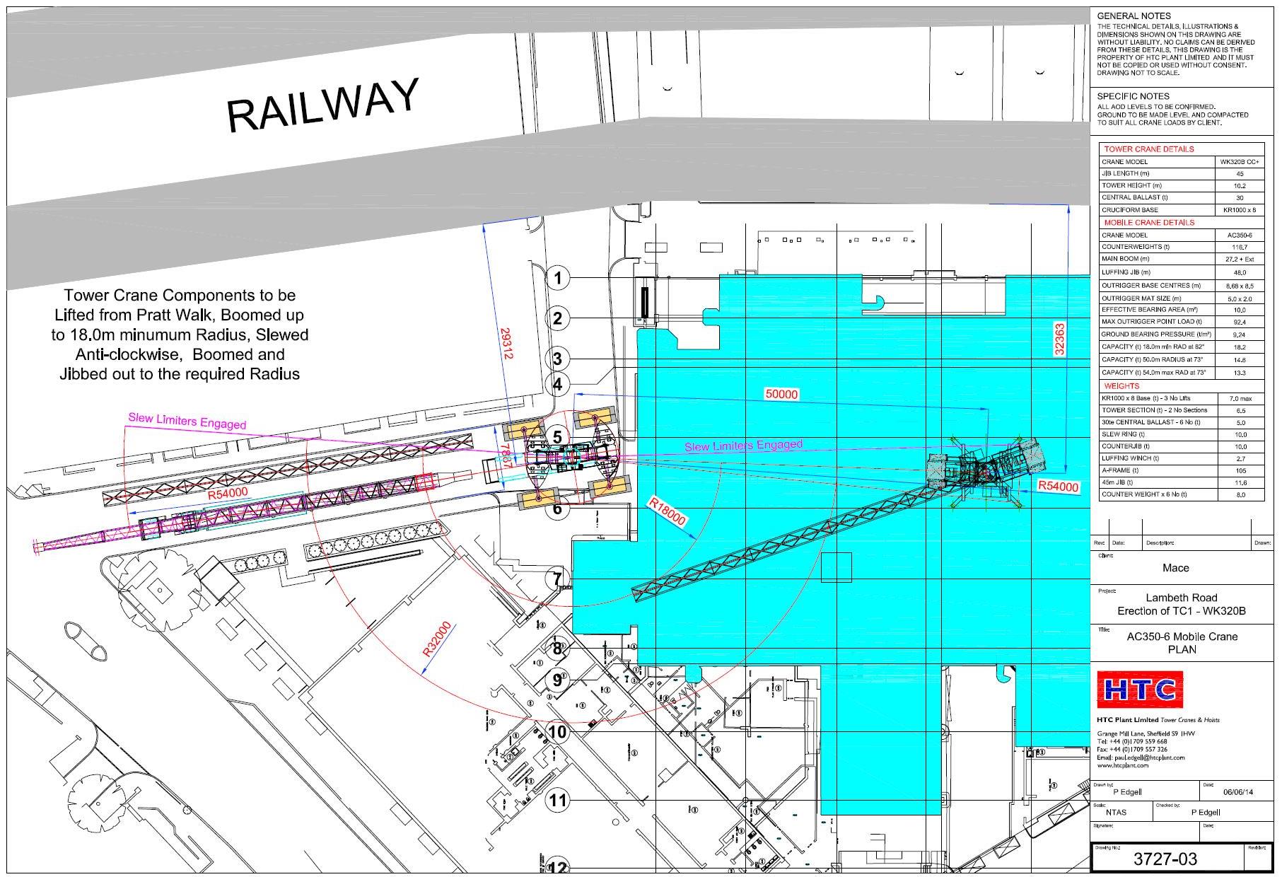
Two of the four mobile crane outriggers I chose to position over basement walls of the existing building. This gave a direct load path of the load into the raft foundation of the building.
The remaining outriggers I had little choice but to position in the road. We conducted a sub-surface survey in order to identify any services near the surface. I verified the pressures from the crane in the same way as designing a foundation using C Nc, Gamma N Gamma …. The cat III checker did similar.
The Issue
Everything was signed off by Network Rail, after much stress and a presentation of our plan the previous week. The mobile crane arrived on the morning of Tuesday 26 Aug 14 and a 60T mobile erected the jib of the AC320-6.
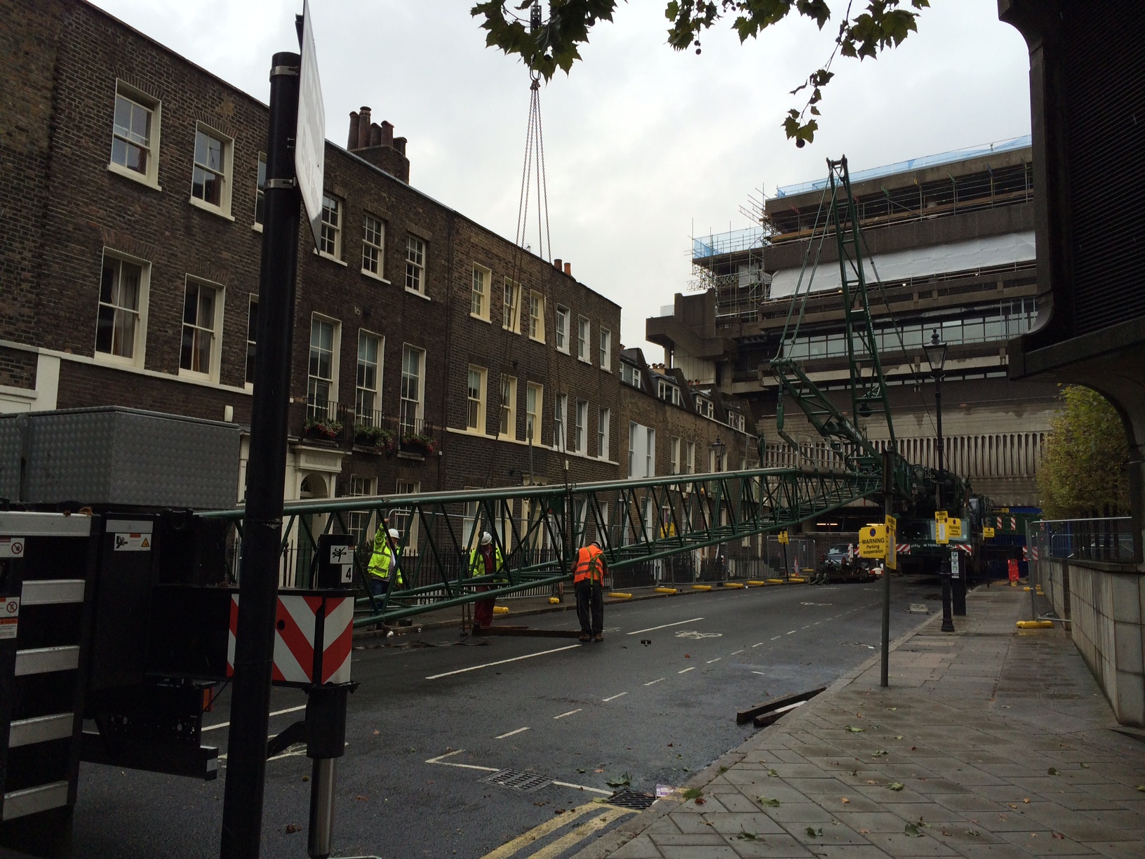
On Wednesday morning we raised the jib of the mobile and the steel wagon arrived.
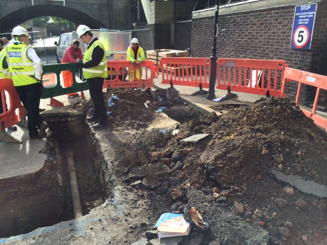
Having realised all 120 tonnes of additional counterweight on the AC-320 the crane, water started to appear from beside one of the four foundations (nearest the railway). I was on site, having earlier signed off the foundations, and lifting operations were stopped immediately. The crane was slewed such that the jib could then be lowered safely back down to the ground. During this time the leak got worse and we discovered that most of the water from the broken water main was making its way from under the road directly into the police station basement, next to the LV switchroom!
We now had a bit of an emergency and potential PR meltdown for Mace! Eventually we managed to isolate the water main and stop the leak. We narrowly avoid shutting down the LV switchroom room and the crane did not de-stabilise in any way.
Immediate Action
Following the event our immediate focus was the safety of the crane in order to ensure it did not collapse and was then the fabric of the building against water. Following this we then had to get Thames Water to site to access the leak and fix it. The Mace project director chose to keep the mobile crane on site (with incurred standing time). We had a backup road closure for the following week so chose to keep the crane on site. Without the backup road closure we would have had a 14 week delay in order to secure another road closure.
Summary
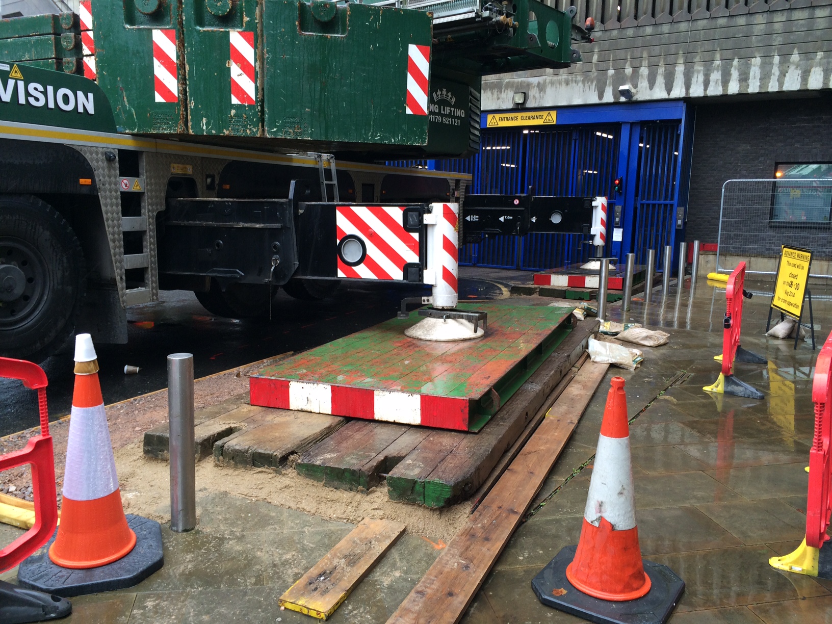
I had identified a water main 1m below one mobile crane outrigger at design stage. I had sought advice from my Mace engineering supervisor who advised that since the average ground pressures were around 100kN per meter square (10tonnes/sq m) this was acceptable and the risk was acceptable.
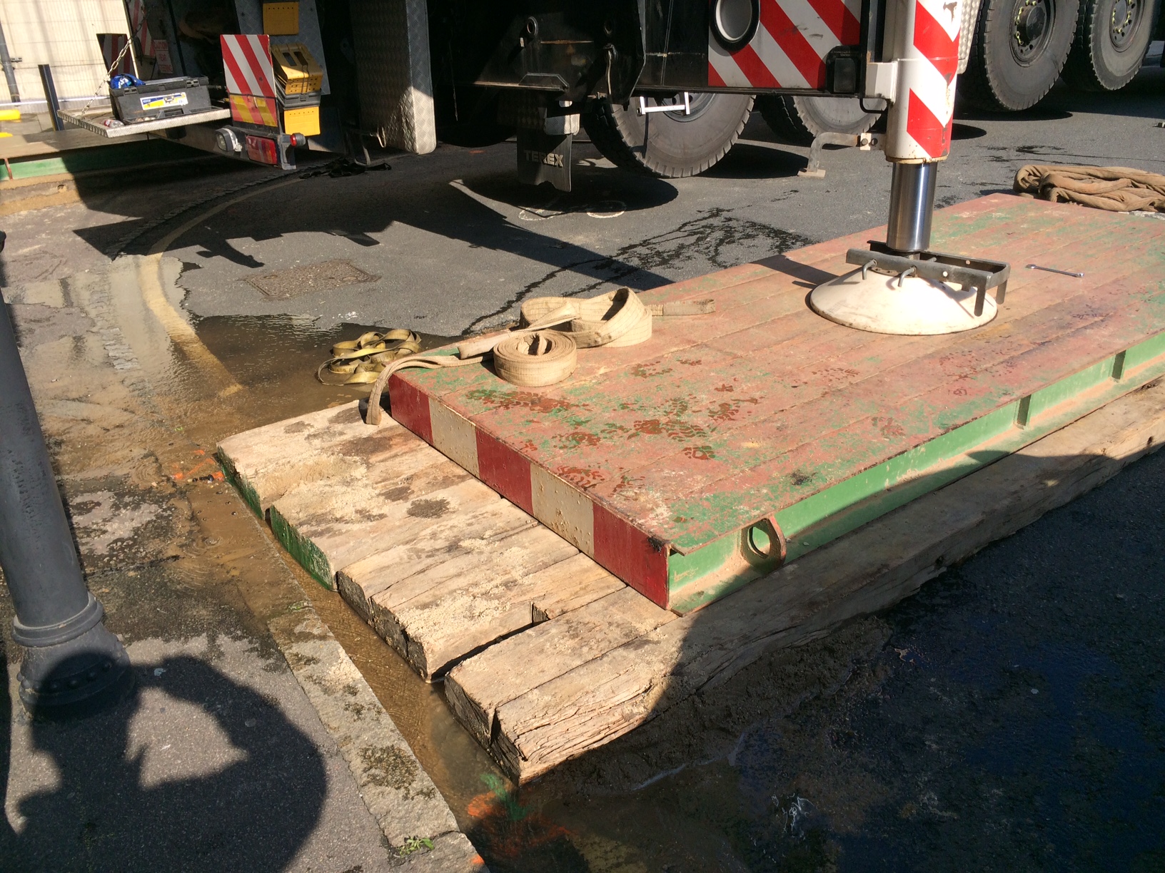
20140827-Mace-109Lambeth-Mobile Crane Outrigger New Matt Configuration
What I didn’t do was communicate this risk adequately. It was not on the mobile crane contractors risk assessment. The police were not aware of the risk. Thames Water were not aware of our plan to position a mobile crane on top of one of their mains.
The leak was caused by a ring fracture. Although Thames Water would not say it the pipe was old but this was no excuse. I re-designed the outrigger foundation with a larger matt and used a deeper layer of sand beneath the matt to ensure pressures were evened out as far as possible. Thames Water replaced the cast iron pipe with a section of HDPE pipe. Network Rail signed off the foundation (again) and the mobile crane was erected successfully. The tower crane grillage was then lifted onto the roof. Erected and then the tower crane was erected and tested. Thankfully all this went seamlessly.
Some significant lessons learnt for me. All part of the experience! Risk registers are key and must be communicated. Get all the stakeholders involved early. If you can reduce risk in any way then do it (ie increase the size of the crane mat).
How long is too long?
This relates to an issue from last month that has now been resolved, but I thought it interesting enough to share and see if anyone would approach the problem differently.
The problem
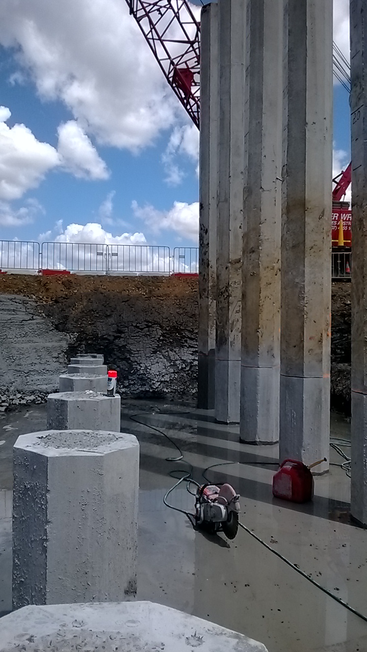
At the start of the project the length of pile that was needing to be cut off was manageable at around the 4m mark. However as progress moved to the middle of the bridge the ground improved and we struggled to reach the underdrive allowance in some piers. This was leaving up to 8m of pile needing to be cut, before breaking down the final metre of pile where the reinforcement is exposed (and then tied into the pilecap).
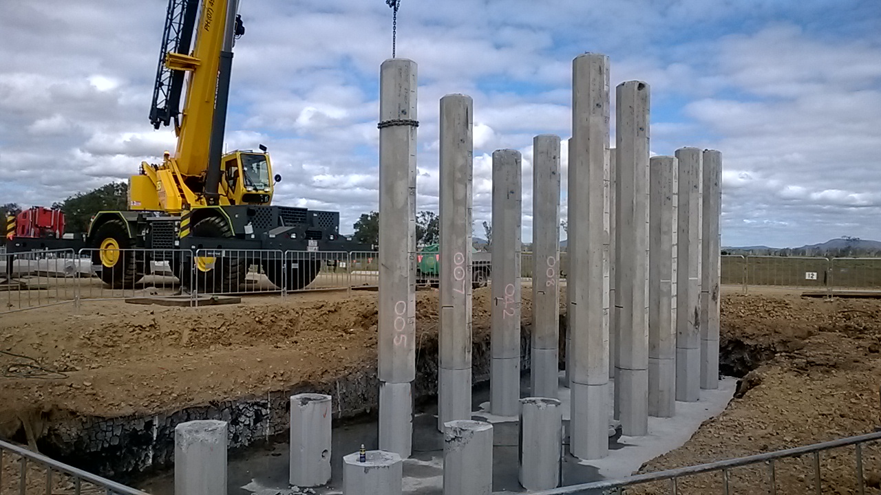
The process for the shorter lengths had been to cut 7 of the 8 sides with a circular saw to a depth of approx. 100mm. This ensured that the strand and reinforcement was cut. A crane would then hook up to the pile and (for some) snap the pile off. For most piles this would not be enough, and the final side would then be cut, or a breaker on a backhoe would tap the pile and it would swing off. With the increase in length the crew cutting the piles became increasingly worried about the stability of the piles prior to the crane hooking onto them. As the pile breakdown was not on the critical path, it happened whenever the crane was not on more critical tasks. – meaning the piles could be cut and sit for a day or two before being snapped off.
The question then came, has anyone checked whether this method is safe? No, the original supervisor was doing what he’d done on other jobs back in the day. He had then handed over to another supervisor and then the length to cut off increased.
The analysis
Safety and the powers would not accept anything that was not signed off by an REPQ (the equivalent of CEng in Queensland). However I still did my own rough check with a free body diagram of the issue to see if I thought it was safe. I took the worst case possible rake on the pile (but still within tolerance – 20mm in 1m) and I assumed a wind loading of 10% of the self weight of the pile. I decided to include the resistance of the reinforcement, even though it was in compression (mainly due to it being confined by the concrete to stop it buckling. Then I negated the concrete in tension and only counted the concrete in compression. Based on my rough calcs I was happy with the situation. The only thing I didn’t consider was accidental loading (in the form of an EWP striking the piles). The piles are made with 50MPa concrete and have 12 x 24mm dia headbars. I did not include the prestressing strand. The diagram below shows my starting point.
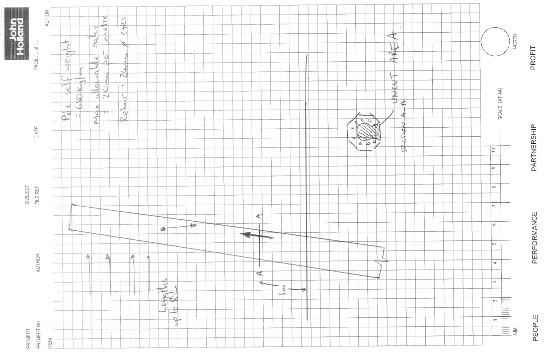
I wanted to see if anyone would approach this a different way to me. I will put my process up after this in a subsequent post (as I don’t want to influence the ideas of others). To give a brief hint there were 2 limits set, one at 4m and the other at 8m with different controls at those points. How would everyone else approach this?
In other news we’ve also started to have a bunch of snakes appearing on site. There were 4 red bellied black snakes on Friday that the catchers had to relocate. Apparently they’re the third deadliest in Australia, might need to put that in my AMS…
BP Placement – for the Phase 1 Students
Morning All,
David recently mentioned that there was a lack of interest in the BP placement for the next turn of the wheel. I am concious that the location doesn’t quite have the same draws as the US/Australia. However, if there are any factor(s) other than geography, e.g. type of work, independance vote, that are holding you back from considering please feel free to pick up the phone. Both Nick and I would be more than happy to speak to any of you about this placement. We will both have different perspectives (I’m a singly and Nick has his young family up here).
It would be a geninue loss if this placement were to fold due to lack of interest.
Cheers,
Brendan
07980 664362
01224 778143
Aberdeen
One of my concerns with coming to BP was that I would have no construction site phase and therefore leave without seeing any tangible results. And whilst the first few months appeared to reinforce this fear, I have seen a reversal this over the last 8 weeks due to an increased pace of life and a number of notable events.
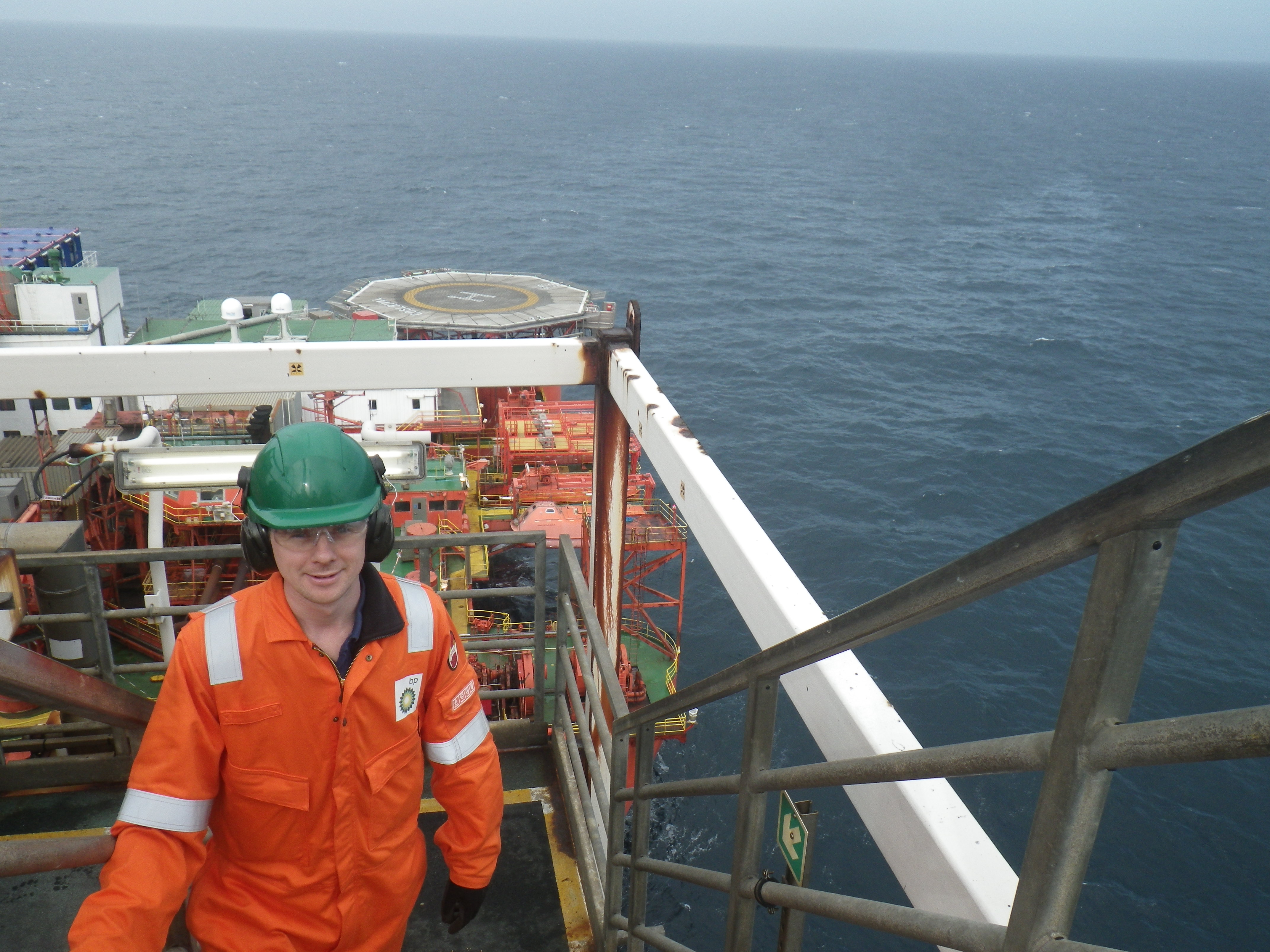
The first notable event was 2 weeks spent off-shore conducting pre-commissioning line walks for the BP Andrew platform. Whilst this had the potential to be very dull, the reality was very different. The main purpose of going offshore was to buddy up with a production technician to trace process systems and confirm that lines as recorded on the P&IDs were in fact in place and that valves and instrumentation was present, serviceable and in the correct position. The fact that there were a number of instances where reality differed from the drawings meant that it was an educational experience, as the line walking team were given the remit to ‘fix’ anything that we could. This involved simple tasks from opening/closing valves to ‘repairing’ instrumentation and safety related devices.
In addition to the line walking activities I was able to engage with the platform management and throughout the course of the two weeks was able to attend the full range of meetings that formed the platform battle rhythm. This ranged from the tool box talks associated with leak testing activities, through production meetings to senior management meetings with onshore. I was also fortunate to be invited to observe an emergency response drill, during which the platform personalities were assessed in their management of a crisis, in this case a helicopter crash. Whilst the language and manner of addressing people was somewhat alien, I believe we would all recognised the activities that were going on.
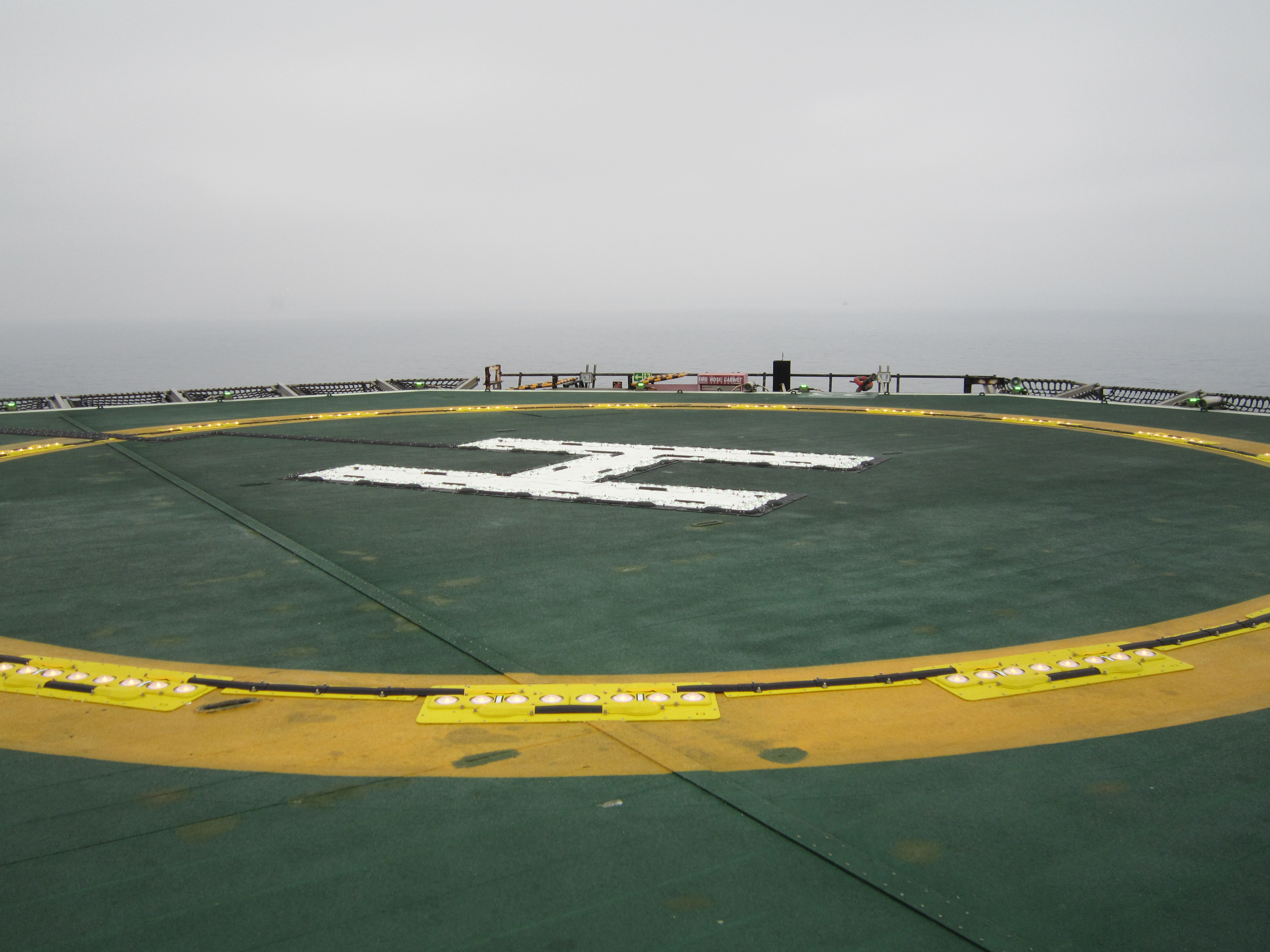
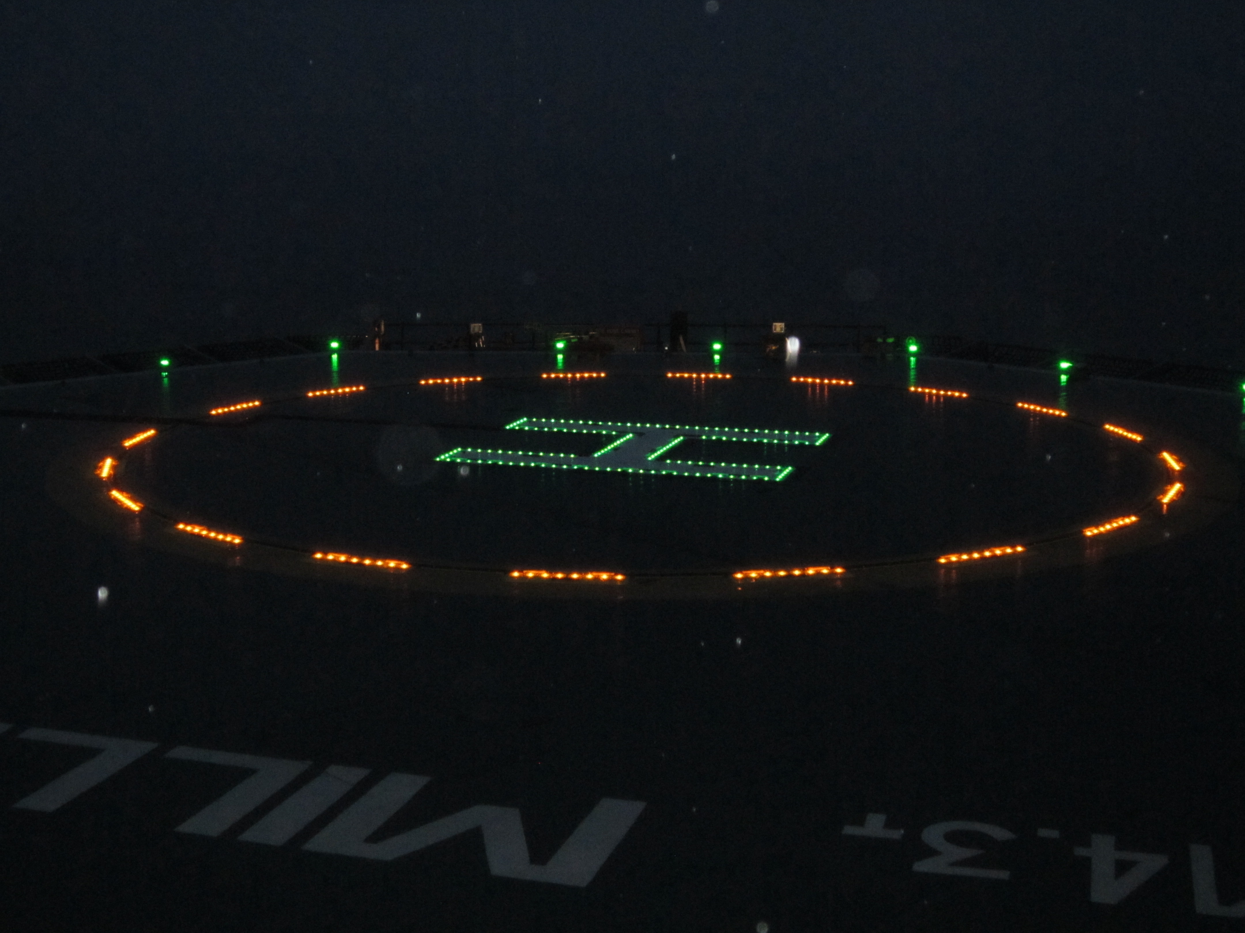
The second notable event was the offshore construction of the helideck lighting trial. Though not an earth shattering achievement and whilst it doesn’t add to the ability of BP to increase production, it was satisfying to take a step forward in aviation safety for the offshore industry. With this activity complete it provides momentum for the regional helideck lighting project which will soon pass to me. I also learnt a huge amount throughout this simple and relatively low value project. I’ll highlight two elements:
-Material tracking. Within the Corp this typically well managed by the G4 chain, not so in industry. Wood Group construction managed to send all the materials for construction offshore except the lights. A fundamental part of the system was missing due to a simple oversight on behalf of the materials coordinator. Because the lights had been gifted to BP by the Civil Aviation Authority there was no purchase order, so no ability to call off the materials. Unfortunately for Wood Group this simple error cost them ~£50,000 in material transport costs and probably the profit on this job.
-Closeout actions. The BP management of change system requires a number of closeout actions to be conducted for even the most simple task. These all appear very simple when sat behind a desk, but the reality of getting individuals to follow through is very different. I have another relatively short turnaround task on the cards, where I will be getting all post-implementation actions closed before the execution if possible and if not a very clear responsibility matrix drawn up.
The photos below show the Orga lighting system installed on the Miller by day and night.
Projects Update
Andrew Helideck Hydrants. I have had sight of this for about 3 weeks. A quick turnaround job that has been labelled by one and all as a ‘hospital pass’. This has to be in offshore execute by the end of November. I have significant concerns with this project for two reasons:
a. The long lead items will not be available until mid-November.
b. A new project execution strategy is being trialled on this job. I know Nick is watching closely as he also has a job that is being trialling the new execution strategy, but the g*t has a little more time in hand and his job isn’t tied to consent to operate.
The two points above effectively means that I’m having to micromanage Costain Upstream on this one and BP are having to provide a lot of support to enable the interface between Costain Upstream and Wood Group for the construction. I think it is achievable but there is very little float in the schedule.
Andrew Hypochlorite Dosing. This is a hangover form the Andrew Area Development (AAD) project that has spent 3 and a half years improving and adding capacity to the Andrew platform. This project was due to deliver a temporary (2 years) chemical dosing skid to deliver sodium hypochlorite into the seawater caissons. This is to replace a faulty electro chlorination package which prevents the built up of organisms in the seawater and firewater system. Projects & Mods will have to take the partially completed design over from the AAD team, which dissolves at the end of September, and complete the onshore detailed design and offshore execute.
The AAD team have identified and purchased a duty/standby pumping skid and designed the pipe run to deliver the solution to the seawater system. The associated challenge is base-lining the progress to date and ensuring that the underpinning engineering is fit for purpose, which will be difficult as there are a number of fundamental documents missing. I expect that it will be necessary to conduct a design review of the available document and retrofit those that are missing/incomplete. The elements of the solution that have been specified appear to be suitable so I expect the this project will move swiftly once the review is complete and corrective actions have been implemented.
Miller Helideck Lighting. Offshore construction complete and now working through the post construction actions. Some of these post construction actions may prove quite difficult to close out, e.g. flickering lights and will require close cooperation with the lighting manufacturer.
Mungo Rescue and Fire Fighting Services. This has now moved into the Define phase and as such the responsibility sits with me as SPA. It has however effectively halted as the business has yet to release funding. Progressing this now sits with my 1-up.
Andrew Sea Water Filter Failure. I was fortunate enough to see the standby in place whilst offshore. The business has taken the decision to refurbish both filters in the near future. The first filter to be refurbished on-shore has now been reinstalled. The second filter will be removed once the platform is back on line. This is being managed by the asset so I will have no further involvement.
ETAP Electrical Controls Upgrade. This project has now reached the end of Select phase, where it is on hold pending a decision from Shell, one of the ETAP partners. Once a decision has been made by Shell to with either retain / dispose of a J-tube (a conduit from the platform topside to the seabed contained within a caisson) the project can complete the Select activities in order to move into Define. This is unlikely to happen until the end of the year and may stretch to early next year as the topside activity is low in value compared to the subsea work and it is not on the critical path.
ETAP Sand Management. Alongside Andrew Helideck Hydrants this project has been consuming a large part of my time. This is a perfect example of scope creep in a job. Unfortunately the scope creep occurred during the Select-Define gate review meeting. (The job should probable have been recycled through Select.) The result was a project that left the Select phase with temporary scope and entered Define a few weeks later with a permanent scope which had doubled in size in terms of packaged plant to be deployed offshore. Whilst the creep has occurred for very good reasons and the prize associated suggests the juice is worth the squeeze, the second and third order implications were not identified. I have spent the last few weeks understanding these effects with my 1-up and communicating this back to the Client (ETAP platform). I have effectively produced a decision brief requiring the asset to commit to a course of action so that this can be driven forward against some challenging scheduled timelines.
In tandem I am reviewing the cost, schedule and scope of work that has been generated by Wood Group for this workscope. The first of four stages, which includes commitments to packaged equipment vendors, has a price tag of £4.2m. The remaining stages are estimated to cost a further £3m, but it is likely that the project will only have to commit a further £0.8m before the end of the 2014/15 financial year. That’s assuming that the partners will agree to the increase in costs from £5m to £9.65m, which will be an interesting conversation later on today.
That’s all for now.
What?? Mass Water In My Shaft & A Little Base Heave
Mass water in the shaft.
Although the UK has had what has been dubbed a mini heatwave the bottom of the shaft has only this week been dried out after a mass water ingress into the site.
Given that I have argued that mass water ingress was not the main risk on site how had nearly 6inches of water entered the site. Well this turned out to be quite a simple. Given that we have open a hole in the ground 25m deep but in a soil with very low permeability the source of the water was in fact the sky in the form of rain. Having not factored Mother Nature’s other elements into my engineers risk assessment we have been faced with removing the water over the height f the shaft. Without having planned for such an incident we did not have a suitable pump in site with sufficient lift to remove the water. In the short term I resorted to using puddle pumps to pump the water in to the depressurisation well heads and using the depressurisation wells to remove the water. This however required negotiations with Crossrail and the monitoring team as the excess water would and did affect the ground water and ground pore pressure readings. After three days of using the depressurisation well system we were able to install a more suitable system that will remain in place over the reminder of the build to deal with future anticipated down pours as we head in to the winter months.
Base heave and a ‘little I told you so’
Issue. After this small embarrassment I was able to redeem myself with sound reasoning for what I recognised as base heave and not incorrect levelling by the junior engineers. The blinding had been poured in sections and over the course of the current basement level (84.60SSL) there were found to be variations in the levels of between 25-100mm and in places severe cracking. The cracking was initial assumed due to the drilling rig moving over the blinding layer and the incorrect levels was blamed on the junior engineers incorrectly setting the level for the concrete. On inspection of the EDMs the levels set were confirmed as correct and consistent at 83.260SSL.
Cause. Given the high pore pressures and the requirement to reduce the pore pressure below the limits set by the design authority (C138, Motts MacDonald) it would seem reasonable that we have experienced a level of base heave. This has shown that the temporary state of the soil in this case can be as little 4 weeks.
Result. The end result has been the removal of the blinding layer and the re-pour of the blinding working platform before construction of the next slab can commence. Having been behind the programme by 2 weeks due to the requirement to install further de-pressurisation the project will now be a further week behind once pouring has been completed.
North Sea Update
Firstly, I apologise that it has been quite some time since my last blog so instead of going into detail on any one subject I will try and write a bullet point list of the things that have been occupying my time and some points of engineering interest:
1) Financial. I technically approved an estimate for £2.5 million and some change. This was for the replacement of the high pressure discharge cooler. This covers the detailed engineering and offshore construction costs for the project and I had to go through and scrutinise each line of the 35 page estimate because there was only £1.8 million left in the budget.
2) Flushing skid Issue One. I had to prove to the process engineer that the formula used by the vendor would work. The vendor had stated in an email the formula they had used to calculate flowrate but the process engineer was unconvinced. Although the query went back to the vendor I thought it was quicker to try and prove it myself. See the attached picture for details and hopefully I’m not wrong because the flushing has now occurred.
3) Offshore. I managed to get offshore again and I did some line walking, which involves trying to decipher process and instrumentation diagrams and then trying to see if what is on the diagram matches what is actually on the asset. I was also involved in an isolation for potable water prior to the issue of a permit.
4) Flushing Skid Issue Two. When there was a problem with the powering the flushing skid it was suggested that the existing hydraulic pressure unit (HPU) may be suitable to flush the system. I did a quick calculation to prove that this wasn’t possible (below):
5) Apart from that, I have been doing all the project engineer stuff for my other projects, which is keeping me busy. Hopefully, my next blog won’t take as long.
What’s wrong with this concrete?
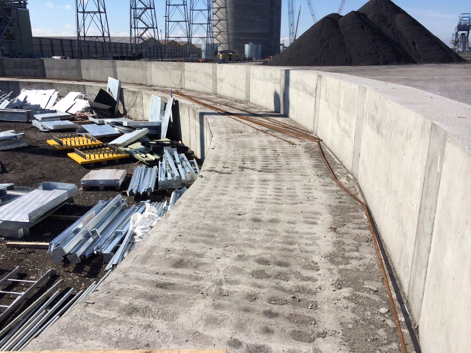
A RC beam for a radial arm coal stacker was recently completed on site as part of a £2M variation order to the original contract. The beam effectively supports a radial arm connected to a conveyor that will distribute coal evenly onto the newly created coal yard slab.
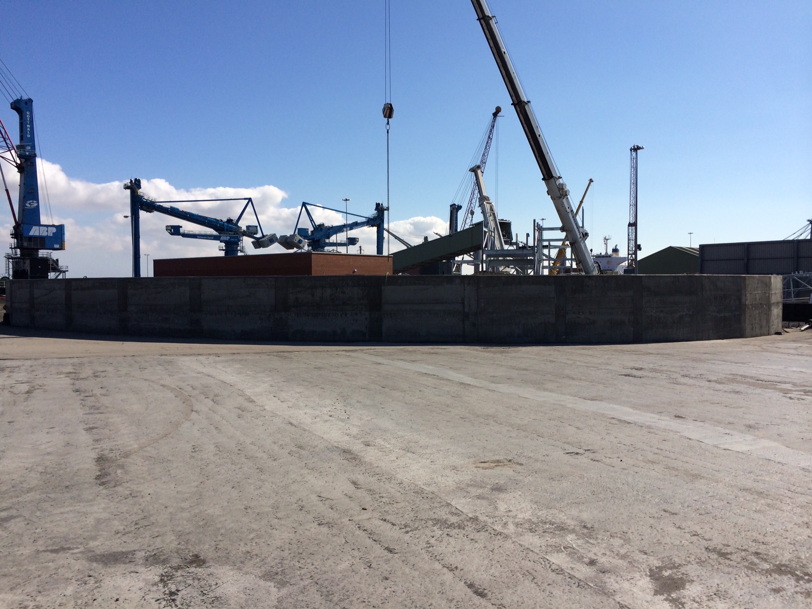
Radial beam for coal yard stacking arm.
The stepped design allows the radial arm to move laterally and distribute the coal. The top concrete surface on the main running section of the radial beam has a series of small cracks tracing the position of the rebar and depressions inbetween as seen in the following photos.
Radial beam top surface.
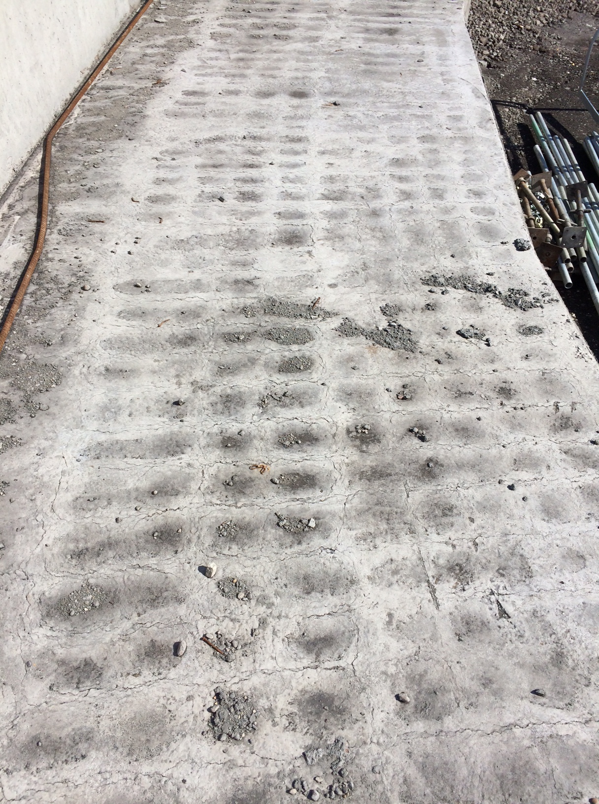
Radial beam top surface in detail.
This has occurred previously across the site (although not as severe) and seems to happen when there is a large volume of concrete poured into reasonably congested rebar.
My initial assumption was that the vertical cover was insufficient (specified 50mm) and the top reinforcement was too close to the surface of the concrete. However I saw the cover being checked prior to the pour and know that it was closer to 60mm than 50mm in most areas.
My next hypothesis was that the concrete was over vibrated creating the problem of segregation where the denser aggregates settle to the bottom while the lighter cement paste tends to move upwards allowing the lattice pattern of the rebar to be seen. This would be further accentuated by the practice of wetting up the concrete pre-pour as I have highlighted on previous blogs.
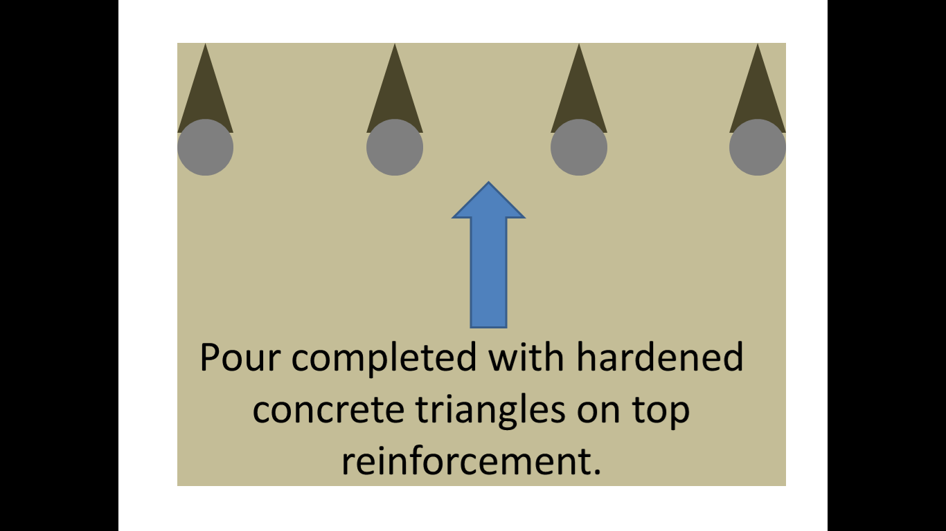
After further thought and reflection after watching the pour I had another theory and have put together a couple of slides to try and explain what I thought was happening. My theory had been that due to the depth of the pour (>2m) concrete was hardening on the top layer of reinforcing bar as it was splashed over it by the pump during the initial stages of the pour. If this was not cleared away it would create an area of hardened concrete above the top rebar that would eventually be covered during the final stages of the pour. As the concrete shrinks during the curing process it would arch over these small triangles of hardened concrete on top of the rebar, creating a surface tension and the eventual cracking and apparent depressions in-between the rebar. I know this was the case in certain areas as I spoke to the engineer in charge and he had to instructed the concreters mid pour to start cleaning off the top rebar as the pour continued due to bad practice from the sub-contractor.
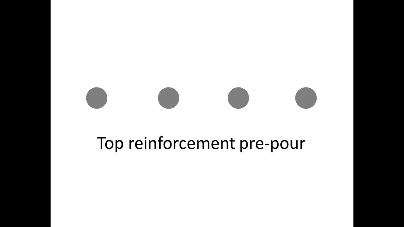
Stage 1.
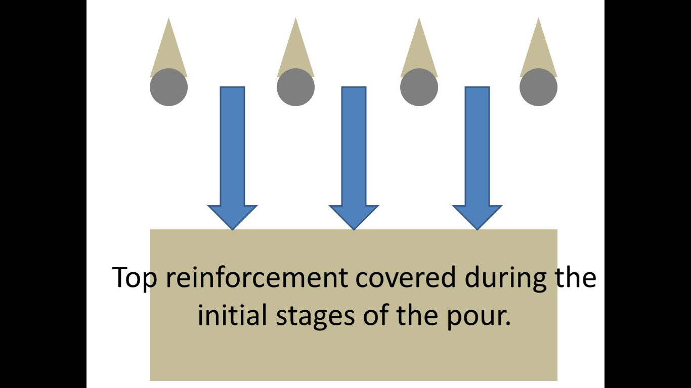
Stage 2.
Stage 3.
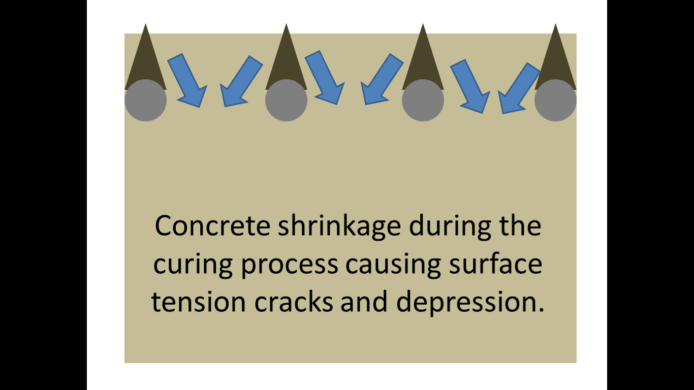
Stage 4.
However I have done some more detailed research and believe that the problem may be plastic settlement cracking. I found the following diagram on the concrete society website.
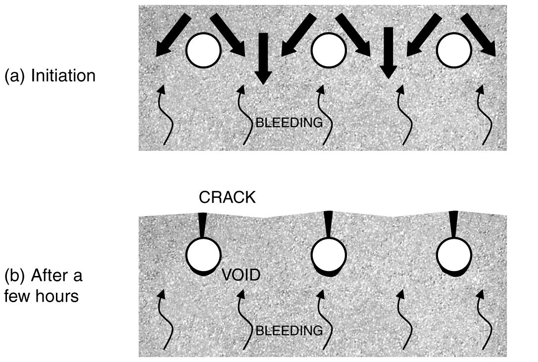
Plastic settlement cracking.
This suggests that the cracks could be caused when the settlement of fresh concrete is restrained by the reinforcement. Plastic settlement cracks can form in young concrete, within the first few hours after placing. As water moves upward through the mixture, the denser constituents move downward accentuated by any over-vibration. This downward movement may be obstructed by the top layer of reinforcement.
The plastic concrete may arch over the top of individual reinforcing bars, bringing the surface into tension. Cracks may develop at regular spacing and usually follow the line of the uppermost bars, giving a series of parallel cracks; there may also be shorter cracks at right angles over the bars running in the opposite direction as seen on the radial beam.
It is sometimes possible for plastic settlement cracks to form on a vertical face where reinforcement has restricted the free flow of concrete within the formwork. In such cases it is possible that the cracks are formed between the lines of the reinforcement.
The concrete can also be supported by the shuttering, causing restraint to the concrete in connected members. This typically happens at mushroom-heads on columns but can also occur at other locations, such as under spacer blocks. Cracks at mushroom heads of columns are generally horizontal. They are also typically 1 mm wide and can cross the full section.
So in conclusion I now believe that a combination of these factors have led to the formation of the cracks.
The radial beam was made up of large (22mm) diameter rebar along the top layer and was reasonably congested (top rebar and links at approx. 150mm spacing). The C32/40 concrete is made using 20mm aggregate and has a slump of consistence S3 100-150mm for use with the pump but is often wetted up even more prior to pouring. The concrete was pumped into place and there was no doubt that some was left on the top rebar due to splashing over it and not cleaned off. It would all be furthered by the tendency to over vibrate during the pour due to the volume.
So what’s the remedial action?
I believe the client is currently unaware of the finish as the beam has been completed well ahead of schedule. This means that remedial action can take place. It is likely that the top layer will be removed by high pressure water (hydro-blasting) down to the top layer of rebar before the surface is re-applied and finished correctly. Contractually I am unsure of where the liability currently lies, I suspect with the concrete subcontractor but I will try and dig into the subcontract to find out.
Why am I concerned?
The reason I have investigated this particular issue, that is outside of my section and responsibility, is 2-fold. Firstly it has happened on site before, including the previous sub-station ground slab and although it was not as severe when I enquired as to why it was occurring, no-one offered a solution.
Secondly, and most importantly, as I am likely to be building a significantly larger substation I do not want the same to happen to the slab I will be required to pour. Therefore any mitigation measures I can take during the pour will hopefully limit my blushes.
So what’s the preventative action?
The tendency for plastic settlement cracks to form may be reduced by adjusting the concrete mix, for example by avoiding gap-graded fine aggregate and reducing the water content, and by appropriate workmanship and control of vibration. Particular care will be required for tall elements especially the 2m+ concrete cable pits required in the sub-station base. In some cases, plastic settlement cracks can be eliminated, rather than prevented, by careful re-vibration of the concrete after they have formed. However, it is important to ensure that the concrete is not over-vibrated as may have been the case in the radial beam.
Are my conclusions correct? Thoughts???
