Archive
Depressurisation Wells
Depressurisation Wells.
During the course of the week I have been overseeing the installation of 16 depressurisation wells. From my previous blog the purpose of depressurisation wells as appose to dewatering wells is to reduce the pore water pressure, rather than stop mass water ingress into the excavation.
Situation. Although open to debate the exact reason for not completing a full depressurisation system prior to starting the excavation is not entirely clear. However the design authority (C138 Mott MacDonald) had stated the required pore pressure required before excavating below each level. From my last blog C502 (primary contractor Laing O’Rourke) are now having to install the depressurisation system 25m below the surface with only 6m clearance between the working platform and the bottom of the 89 slab level. To make the drilling more complicated, 12 of the 16 wells need the well tip outside of the contiguous pile wall, but avoiding the new crossrail tunnels running adjacent to the Blomfield Box being constructed by C510.
Soil. The soil characteristics are typical of London Clay and the Lambeth Group, over consolidated fine grain soil with laminations of course grain soils. Primarily a low permeability soil with a low voids ratio the soil is very stiff with high shear strength as a result it is extremely difficult to excavate. Added to this it is believed that at 25-30m below the current slab level (83 SSL) are the chalk and silt layers of the Lambeth Group. The risk here is the believed 40m head of the artisan water below within the chalk. Penetrating this would result in a mass water ingress and flooding of the Blomfield box, a potential risk to the project and to life.
Drilling Rig. The drilling rig being used is a Berretta T 57 Geo, which usually has a 10.5 m fixed mast. Given the high strength of the soil, the possibility of pile overspill the drill and the restricted head room the drill was modified rather than use smaller drilling rig with insufficient power to penetrate the soil efficiently. In addition the drilling rig would need to be articulated in order that it could drill at an angle to allow the well tips to be outside of the pile wall. As a result the drilling rig had a smaller mast at 5.5m and hydraulic rams to adjust the drilling angle fitted, all of this was completed in Italy at the expense of C502.
Depressurisation Wells
The well system being used is an ejector system that uses a vacuum to reduce the pressure within the well to set up a artificial low pressure and hydraulic gradient which is intended to draw the porewater from the soil and reduce the pore pressure. The low permeability of the soil means that the seepage rate of the soil is not sufficient to lower the porewater pressure to the required levels set by C138. Unlike an air induced vacuum as used on deep well systems the ejector system induces a vacuum by pumping water into the ejector well tip which sets up a venturi vacuum. The amount of water that is extracted must account for the water pump through the ejector to set up the ventral vacuum.
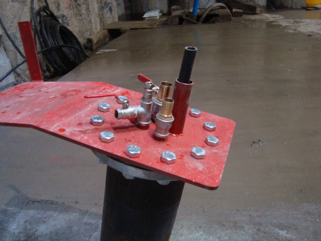
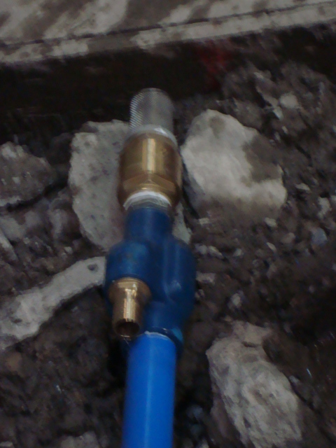
Pictures Right to Left, Well head showoing water inlet and outlet, ejector pump head, water injected through left connection, water removed from main blue pipe.
Drilling Operation.
Angle of Attack. In order to place the wells outside of the pile wall we determined the end location of the wells at 65m, and the location of the C510 running tunnels at 72/73m. This gave us a angle of between 15-20o and at a distance of 2.2m from the pile face.
Drill Setup. As the engineer overseeing the drilling I have been setting up the drilling points and then confirming the drill is at the correct angle prior to drilling. This has been done by using the EDM to determine the Easting and Height of two points on the mast, then using Trig to determine the angle of the mast.
Drilling speed . The speed of drilling is governed not by how fast the drill can be forced through the soil but how quickly the cuttings can be cleared from the well. The drill uses a drilling tip and drilling rods using drilling mud to bring the cuttings to the surface, not an auger.
Drilling Mud. Drilling mud is a mixture of water and additive to create watery slurry. The type of additive used is dependent on the soil type. The drilling mud acts as; a lubricant for the drilling tip, as a well filler similar to bentonite to maintain horizontal pressure to keep the well open and as medium to carry the cuttings clear of the well. Drilling mud is pumped through the centre of the drilling string to the tip, it then picks up cuttings and is forced to the surface. The drilling mud then passes through a series of settlement tanks and then recycled. The types of addictive for different soil types are not an area that I have a great deal of information at this time.
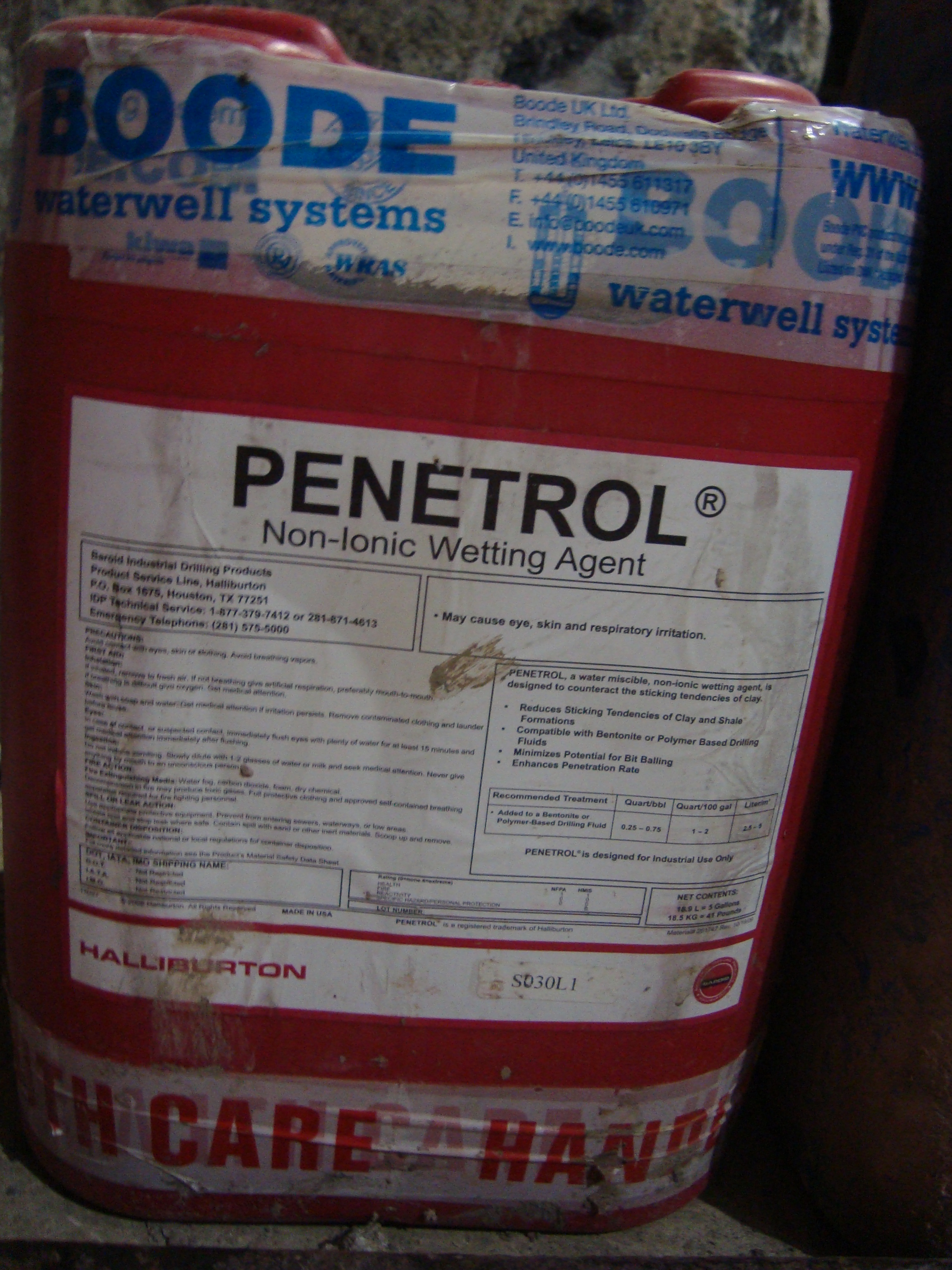

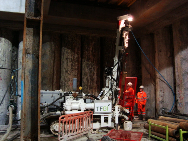
Pictures Right to Left, Drililng mud additive, Drilling rig set at 15 degrees, drilling rig
