Archive
Fixing mistakes
I’ve mentioned in a few comments there are now getting to be a number of repairs that are needed on parts of the substructure. With a bit of luck what I’ve learnt may help anyone else that ends up with similar issues in the future, or feel free to tell me where I’ve gone wrong!
Problem
They fall into 2 categories – damage after the works and incorrect procedure resulting in remedial action. There are a number of causes for both starting to happen in my opinion. Initially there was a big push to get productivity up, then there was the need to reduce costs. This started with reducing the numbers on site and we are now in the situation of reducing hours for some of the work groups. This means moving people about the site and workers jumping from one crew to another. This leads to procedures not being followed and a new learning period if the crew changes and the new bloke gets left to stay back and finish off the pour. However I digress.
The photo below shows the damage done to one of the pedestals on pier 10. The workers that stripped the formwork said nothing about it happening, and the concrete that broke off is sound, as is the concrete remaining on the pedestal. The formwork could have been removed at an angle, or there could have been a lack of form oil on those sides. I think the most likely cause is that a sledgehammer was used to help persuade the forms off, not that anyone is owning up to that.

Solution
To fix the problem the concure had to be removed, which proved much more difficult than first thought. Most curing membranes on the approved list for transport and Main Roads degrade after a period of 6 to 8 weeks (normally under UV light). However trying to remove the membrane before this isn’t that easy. High pressure water blasting isn’t effective. There are a lot of environmental controls involved with sand blasting (not to mention the cost involved). That only leave mechanical removal, or in this case a man scrubbing it off with a scouring pad fitted to a buffer. The cost of this work now, however is preferable to doing the rework later in the program (after 6-8 weeks) as the girders will have been landed and cross girders poured. While it is still possible, the access is severely restricted and will take much longer to perform.
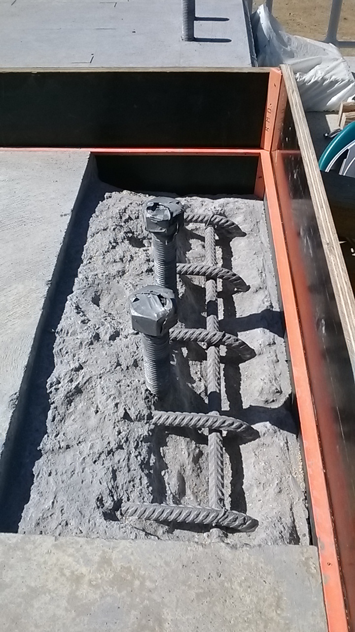
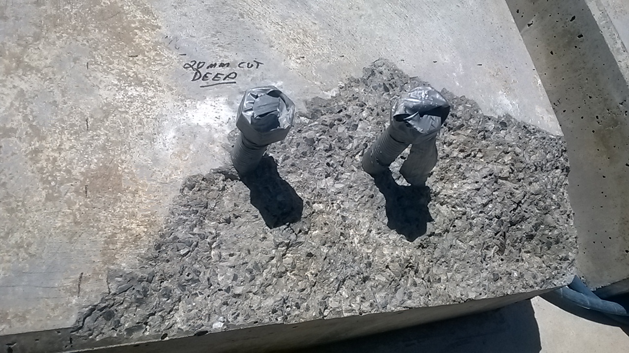
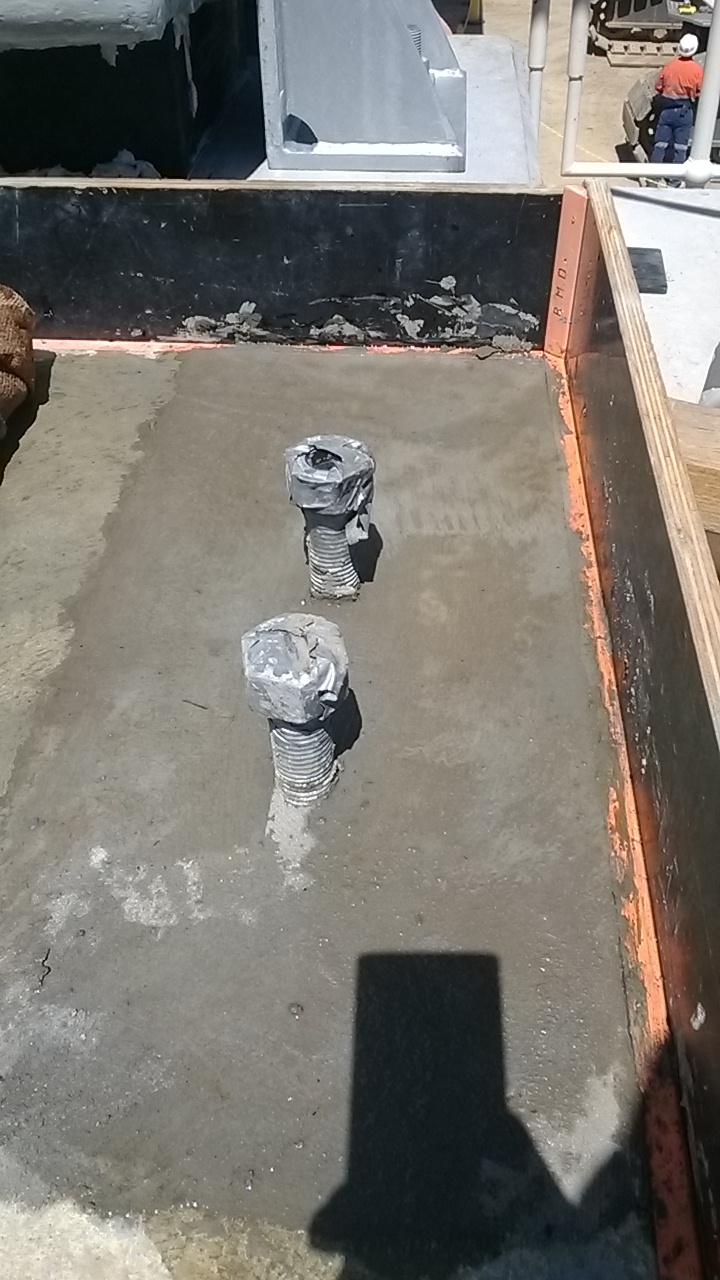
Back to the solution to the breakages. The concrete had to be cut out to a depth of 20mm and then broken out to expose the reinforcement. There needed to be sufficient room behind the bars to ensure that the aggregate flowed behind the bars and made a strong bond. See photo above for what it looked like after being formed up. After this the area was cleaned out and dampened (but no free water on the surface.The next stage was coating the steel and concrete in Nitobond AR. This is a 2 part epoxy that is designed for bonding fresh concrete to old concrete (or concrete that has already set). I did consider using other products such as Renderoc HB70, however the client preferred using a concrete patch for the aggregate component. The other side of the pedestal had no exposed reo and so a small bar of reo was chemset into the pedestal to provide a sound anchor for the new concrete. IT was a different 2 part epoxy used for this – Hiti have RE 500 which is very common, but expensive, we used Power fasteners PF PRO but there is also a chamset series of products by Ramset. The combination of the steel as an anchor and the nitobond should stop any problems of the repair falling out in the future – as due to a different batch of concrete being used there have been instances of repairs just falling out, with the differential thermal expansion of the two mixes.
The Other Problem
The issues with our own procedures not being followed have led to a different set of repairs. On the headstock the construction joints for the pedestals need to be prepared the day after the pour. To make the preparation of these joints easy we apply Rugasol (made by Sika) after the pour is finished, there are other equivalent products by Parchem, Ramset etc that could be used. Using this makes the greencutting the following day much easier and can give a very good clean construction joint. The rugasol should be worked into the area of the joint (it can be sprayed on, but this doesn’t work with the curing method we are using). If it is not worked in then when the damp hessian is placed ontop and flooded with water the Rugasol can spill out over the entire headstock. This has happened a couple of times, and while the impact isn’t dramatic it reduces the quality of finish on the surface. The inspectors have issued an NCR and stated that they want the surface dressed to achieve a class 2 finish – this is well within their rights as that is what is in the contract. They went a step further though (too far in my opinion) and have instructed us to coat the surface with Xypex Modified. This is a waterproofing sealant that is normally used in marine environments, reservoirs/dams and swimming pools. As there is no cracking or reduction in cover depth I think this is excessive, and can’t think of a reason for this being required for what was an aesthetic issue. Thankfully this is a one off problem. With more supervisors now on site the workmanship issues should disappear. (I planned to show some photos of this, but I’m on leave now and have left them back in Oz!)
Cranes alongside railways
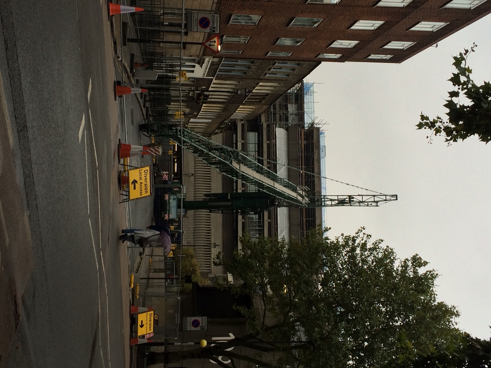
As well as my work on the South Bank Tower I am also the Construction Engineer for Mace at a small site in Lambeth, at a Metropolitan Police Station. This police station is a forensics lab, headquarters for a firearms unit and also a communications HQ for police and fire calls.
Maces scope of works is predominantly M&E. We are relocating the existing plant onto the roof of the existing five storey structure. Originally built in the early 1970s it was first used by the Royal Mail as a sorting office and as such is a very robust structure with 14 and 18inch thick floor slabs, with RC columns in approx. a 10m grid.
In order to relocate the plant onto the roof, a steelwork grillage is to be built in order to allow the high permanent dead loads to be bear directly on top of the existing RC columns, instead of the roof which obviously is not strong enough. Being London the site is particularly constricted. To the east is the rail mainline into Waterloo (the Reading line), to the south a narrow road, to the west there is no access since there is a hotel and to the north there is a small residential street used by the police for access.
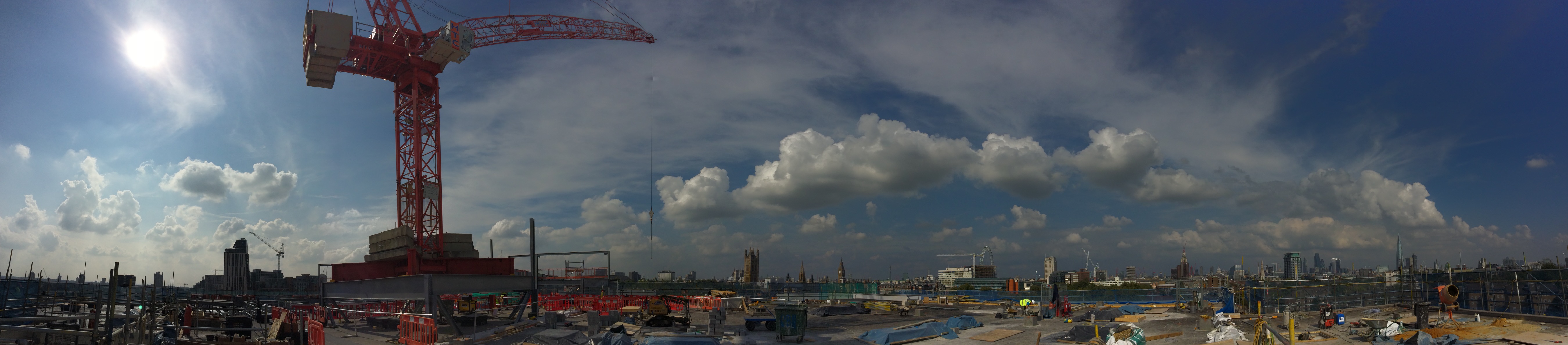
The key challenge for me has been to plan how to erect a tower crane on the roof of the existing building, which will lift all the plant into its position. This needed to be achieved with limited access and immediately beside a live railway. Network Rail require anyone working beside the railway to have an agreement in place and any works which could impact the railway to be signed off by their Railway Asset Protection Team. As part of the approval process the principal contractor has to nominate a Designated Project Engineer (my role) and a Contractor Responsible Engineer (min Chartered Engineer).
Network Rail operates in a risk focused manner. They trust nobody and everything that could potentially impact the railway is scrutinised to ensure the risk has been appropriately managed. Obviously using a mobile crane to erect a tower crane on the roof of an existing building and then operating a tower crane to lift pieces of plant, up to 10 tonnes in weight, is relatively risky.
Managing the risk effectively, thereby reducing the level to an acceptable level for Network Rail, required prolonged engagement and forward planning. We had to demonstrate we had explored all alternative options and the chosen option then had to be designed and category III checked. This task was doubled with having to design and check both the mobile crane, and the tower crane.
Tower Crane Grillage
For the tower crane, in order to progress the early design of the tower crane I undertook initial design feasibility to determine the scheme was viable and also give the steel fabricator indicative sizes of beam for pricing. I then gave the detailed design and analysis of the crane grillage (utilising the permanent works steelwork) to a temporary works designer to complete. In order to verify the existing structure was adequate to support the tower crane loads, combined with plant loads, I then undertook a detailed analysis of the building.
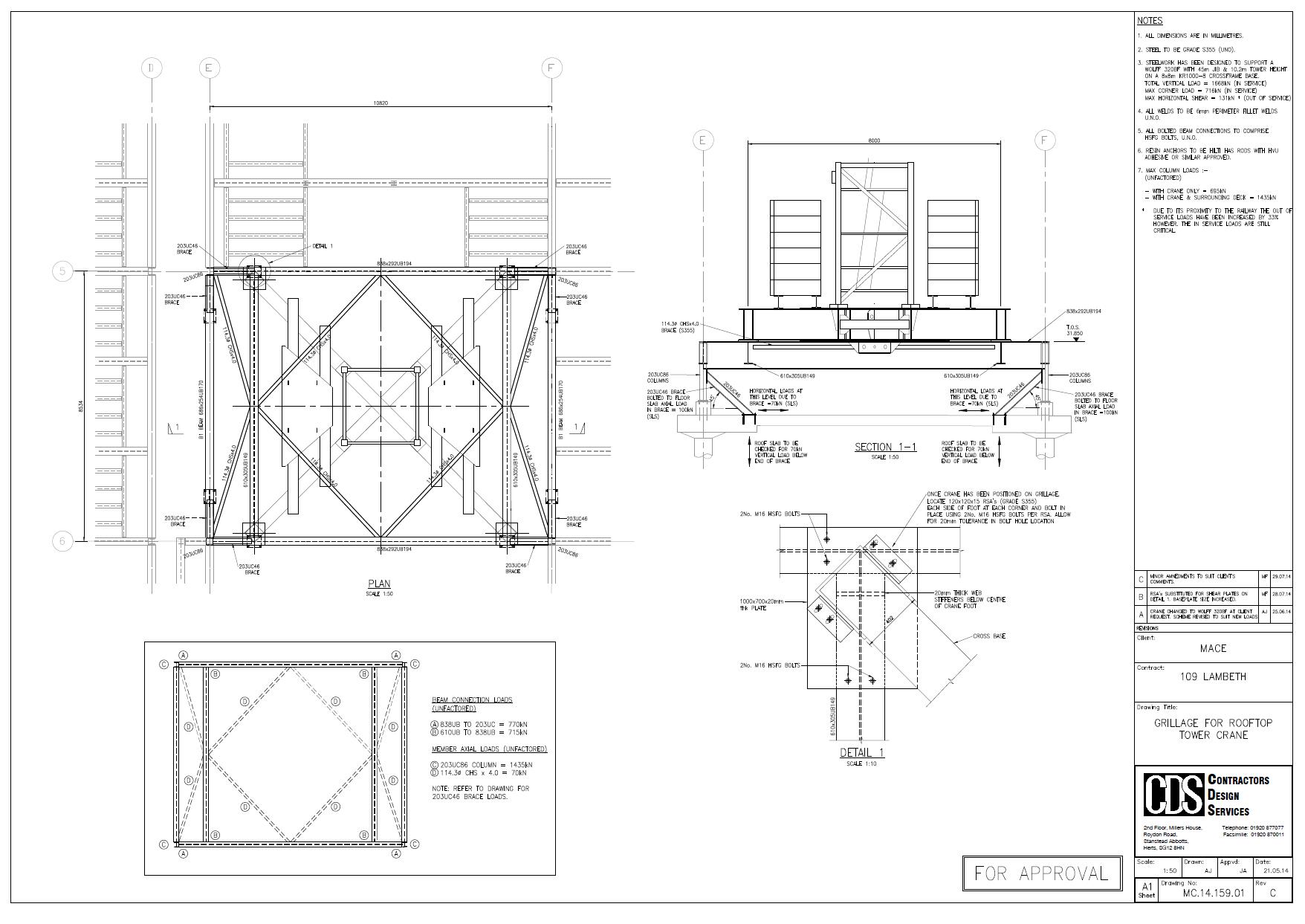
The steelwork grillage design and building verification was then category III checked by an independent engineer.
Mobile Crane
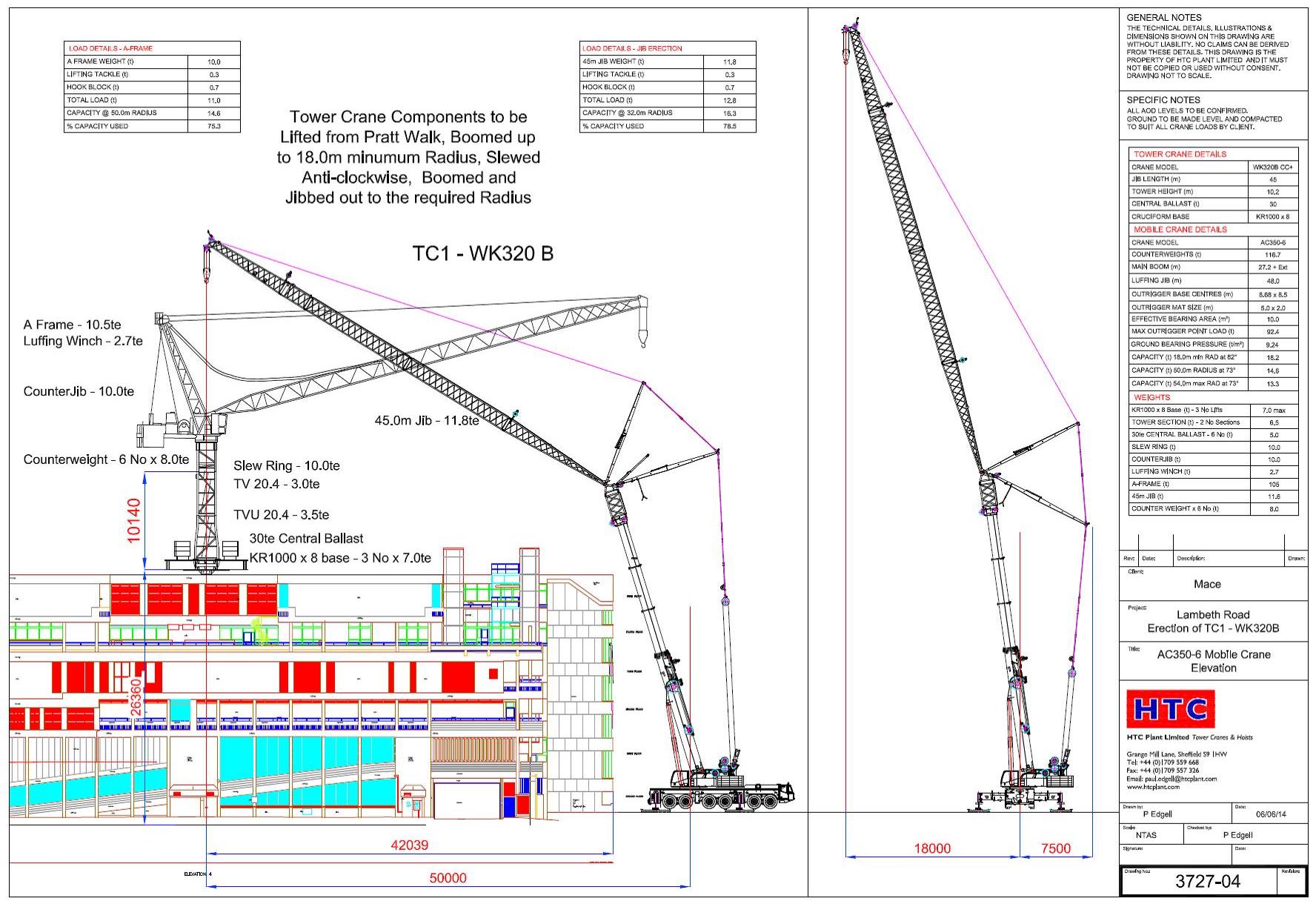
I undertook the design of the mobile crane foundations. The only workable position was for the 320 tonne mobile (a Terex AC350-6) was to situate it in Pratt Walk, an urban road between the police station and a row of occupied residential house (separating the crane and railway).
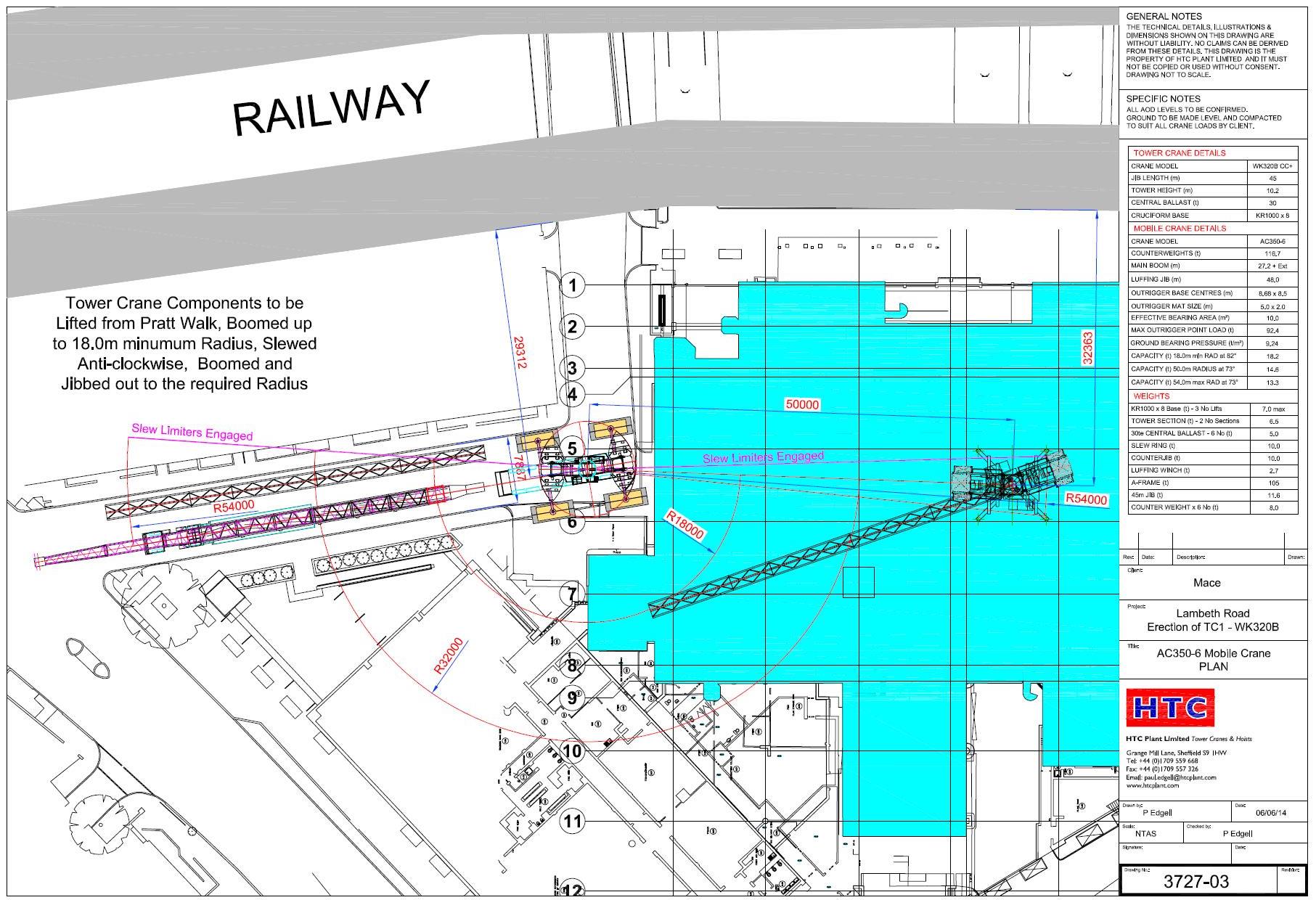
Two of the four mobile crane outriggers I chose to position over basement walls of the existing building. This gave a direct load path of the load into the raft foundation of the building.
The remaining outriggers I had little choice but to position in the road. We conducted a sub-surface survey in order to identify any services near the surface. I verified the pressures from the crane in the same way as designing a foundation using C Nc, Gamma N Gamma …. The cat III checker did similar.
The Issue
Everything was signed off by Network Rail, after much stress and a presentation of our plan the previous week. The mobile crane arrived on the morning of Tuesday 26 Aug 14 and a 60T mobile erected the jib of the AC320-6.
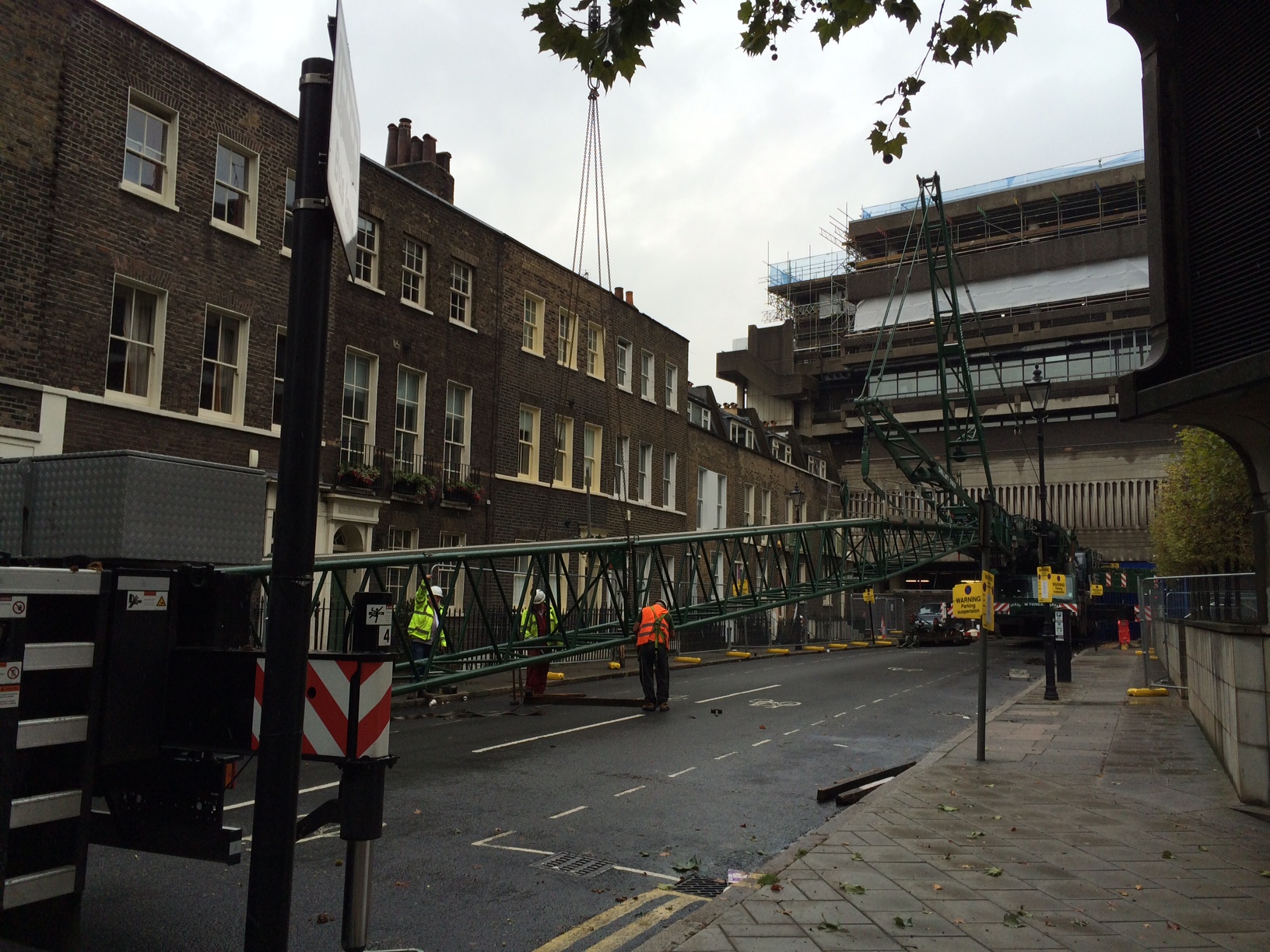
On Wednesday morning we raised the jib of the mobile and the steel wagon arrived.
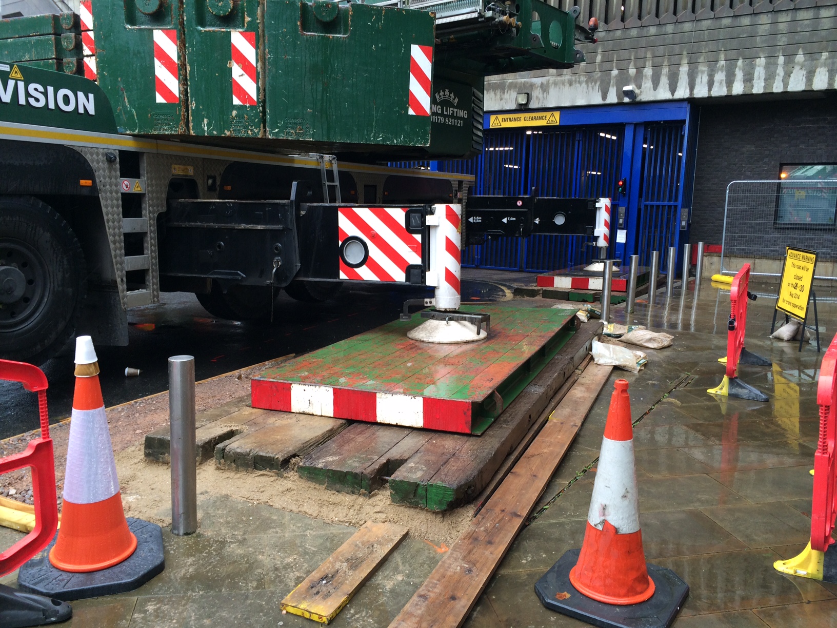
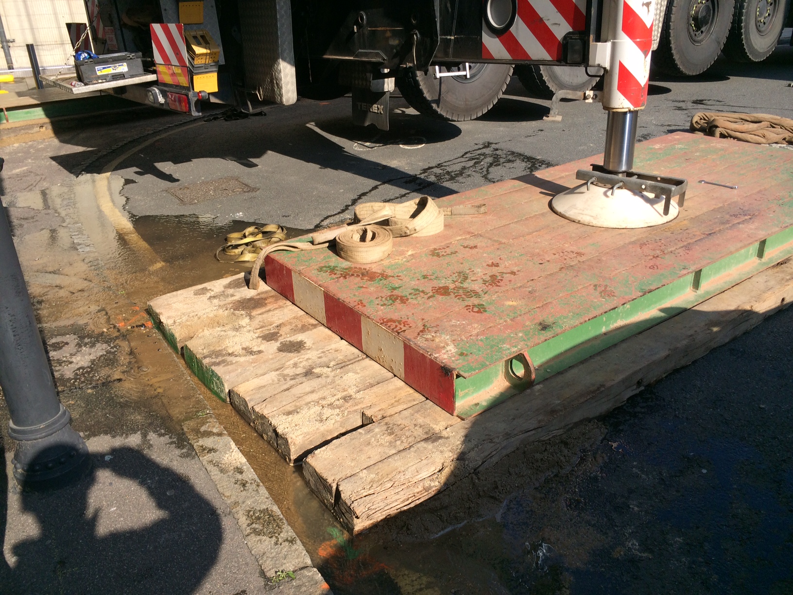
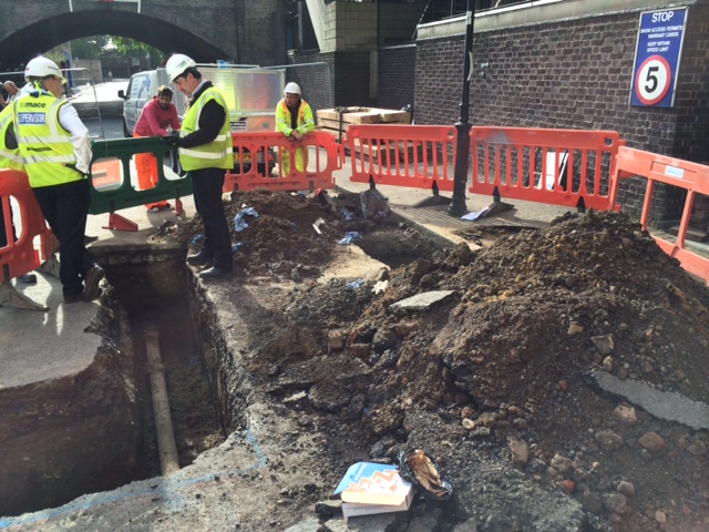
Having realised all 120 tonnes of additional counterweight on the AC-320 the crane, water started to appear from beside one of the four foundations (nearest the railway). I was on site, having earlier signed off the foundations, and lifting operations were stopped immediately. The crane was slewed such that the jib could then be lowered safely back down to the ground. During this time the leak got worse and we discovered that most of the water from the broken water main was making its way from under the road directly into the police station basement, next to the LV switchroom!
We now had a bit of an emergency and potential PR meltdown for Mace! Eventually we managed to isolate the water main and stop the leak. We narrowly avoid shutting down the LV switchroom room and the crane did not de-stabilise in any way.
Immediate Action
Following the event our immediate focus was the safety of the crane in order to ensure it did not collapse and was then the fabric of the building against water. Following this we then had to get Thames Water to site to access the leak and fix it. The Mace project director chose to keep the mobile crane on site (with incurred standing time). We had a backup road closure for the following week so chose to keep the crane on site. Without the backup road closure we would have had a 14 week delay in order to secure another road closure.
Summary
I had identified a water main 1m below one mobile crane outrigger at design stage. I had sought advice from my Mace engineering supervisor who advised that since the average ground pressures were around 100kN per meter square (10tonnes/sq m) this was acceptable and the risk was acceptable.
20140827-Mace-109Lambeth-Mobile Crane Outrigger New Matt Configuration
What I didn’t do was communicate this risk adequately. It was not on the mobile crane contractors risk assessment. The police were not aware of the risk. Thames Water were not aware of our plan to position a mobile crane on top of one of their mains.
The leak was caused by a ring fracture. Although Thames Water would not say it the pipe was old but this was no excuse. I re-designed the outrigger foundation with a larger matt and used a deeper layer of sand beneath the matt to ensure pressures were evened out as far as possible. Thames Water replaced the cast iron pipe with a section of HDPE pipe. Network Rail signed off the foundation (again) and the mobile crane was erected successfully. The tower crane grillage was then lifted onto the roof. Erected and then the tower crane was erected and tested. Thankfully all this went seamlessly.
Some significant lessons learnt for me. All part of the experience! Risk registers are key and must be communicated. Get all the stakeholders involved early. If you can reduce risk in any way then do it (ie increase the size of the crane mat).
How long is too long?
This relates to an issue from last month that has now been resolved, but I thought it interesting enough to share and see if anyone would approach the problem differently.
The problem
At the start of the project the length of pile that was needing to be cut off was manageable at around the 4m mark. However as progress moved to the middle of the bridge the ground improved and we struggled to reach the underdrive allowance in some piers. This was leaving up to 8m of pile needing to be cut, before breaking down the final metre of pile where the reinforcement is exposed (and then tied into the pilecap).
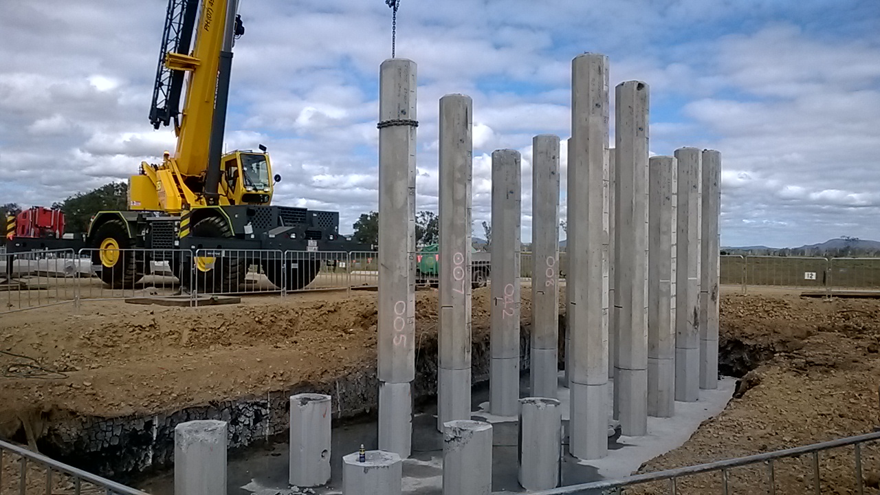
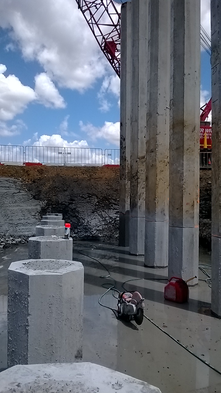
The process for the shorter lengths had been to cut 7 of the 8 sides with a circular saw to a depth of approx. 100mm. This ensured that the strand and reinforcement was cut. A crane would then hook up to the pile and (for some) snap the pile off. For most piles this would not be enough, and the final side would then be cut, or a breaker on a backhoe would tap the pile and it would swing off. With the increase in length the crew cutting the piles became increasingly worried about the stability of the piles prior to the crane hooking onto them. As the pile breakdown was not on the critical path, it happened whenever the crane was not on more critical tasks. – meaning the piles could be cut and sit for a day or two before being snapped off.
The question then came, has anyone checked whether this method is safe? No, the original supervisor was doing what he’d done on other jobs back in the day. He had then handed over to another supervisor and then the length to cut off increased.
The analysis
Safety and the powers would not accept anything that was not signed off by an REPQ (the equivalent of CEng in Queensland). However I still did my own rough check with a free body diagram of the issue to see if I thought it was safe. I took the worst case possible rake on the pile (but still within tolerance – 20mm in 1m) and I assumed a wind loading of 10% of the self weight of the pile. I decided to include the resistance of the reinforcement, even though it was in compression (mainly due to it being confined by the concrete to stop it buckling. Then I negated the concrete in tension and only counted the concrete in compression. Based on my rough calcs I was happy with the situation. The only thing I didn’t consider was accidental loading (in the form of an EWP striking the piles). The piles are made with 50MPa concrete and have 12 x 24mm dia headbars. I did not include the prestressing strand. The diagram below shows my starting point.
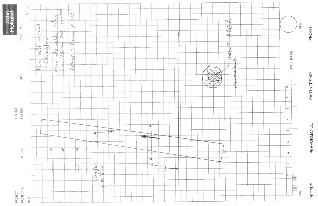
I wanted to see if anyone would approach this a different way to me. I will put my process up after this in a subsequent post (as I don’t want to influence the ideas of others). To give a brief hint there were 2 limits set, one at 4m and the other at 8m with different controls at those points. How would everyone else approach this?
In other news we’ve also started to have a bunch of snakes appearing on site. There were 4 red bellied black snakes on Friday that the catchers had to relocate. Apparently they’re the third deadliest in Australia, might need to put that in my AMS…
