Archive
Water, water, everywhere
It’s been a hectic couple of weeks, with several issues occurring as we excavate further but I try to remind myself that its all great experience!!
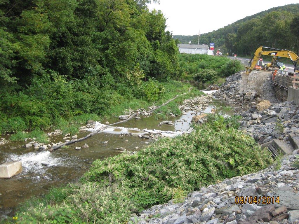
Looking north; river flowing towards the viewer. Dewatering partly in place – dammed upstream and down, with water being pumped around site.
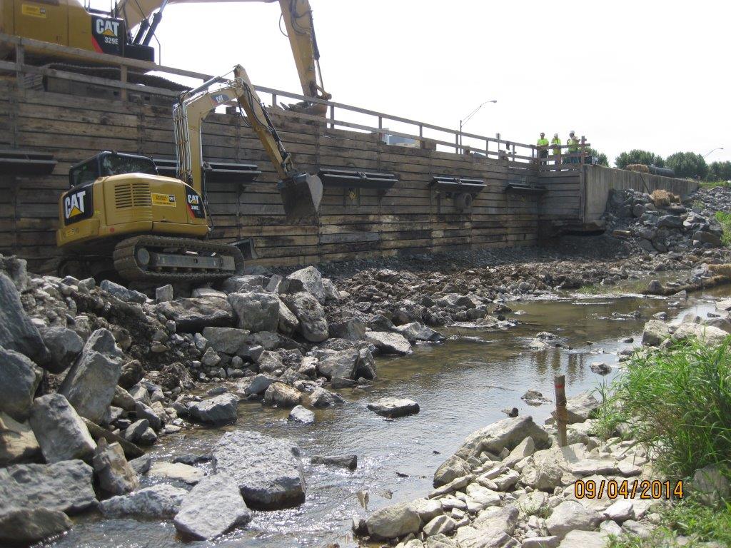
Looking at site from across the river, supposedly mostly dewatered. Note stake in foreground shows limit of excavation for the dug-toe.
As usual, pretty much everything problematic has been a result of water! Upon reaching the limit of excavation at the base of the shoring (13ft) and reviewing submittals for the structural fill I had some major concerns:
- The excavation was starting to get wet underfoot, plus I could see (in concert with some local knowledge) that the visible river at 1-2ft deep was actually running several feet deeper and was flowing under our site following its original path under the retaining wall and the highway. This tied into the issue that was raised by the tie-back drillers that they were hitting water at 15-20ft. Annoyingly the original borehole logs down to 28ft do not show any indication of water on them – not helpful!
- The dewatering was having minimal effect; there was more pumping to occur within the two dammed walls (pic top left) but it was evident that it would be nigh on impossible to dry the area in order to excavate the ‘dug-toe’, and then lay the proposed structural fill (lean clay) and compact it to 98% of lab dry density. (Readers may see the system as somewhat Heath-Robinson but we are ham-strung by the Env Agency design manual, and the inability to have any plant in the water – it was too late in the day to design a causeway and build a by-channel, plus see notes at para 1)
- As mentioned above, the submittal for the structural fill was a low-plasticity clay – the purpose was to produce an impervious layer across the site. However, if you have a look at Sheet C-303 below you will notice that the clay extends from the base of the toe all the way up to the edge of the shoring; more concerning is that the concrete wall sits on it. How on earth is a wall going to be structurally stable sitting on clay which will continually be dried out and saturated (note the mark of ‘normal water level’ – 5ft above where it is at present)???
- The damaged wall in 3 x 30ft sections had fallen at different angles. I managed to work out what was where by measuring what was poking out, and what was embedded and at what angle. The concern was the amount still embedded below the limit of excavation, and that a huge amount of sediment was entering the river downstream of the site whenever the wall was being broken up (additional evidence that the river is flowing under the site).
- A void was visible on the south side of the site underneath the existing wall – clearly caused by erosion once the wall had fallen. Rebar was also exposed and the water joins were ripped (see pic).
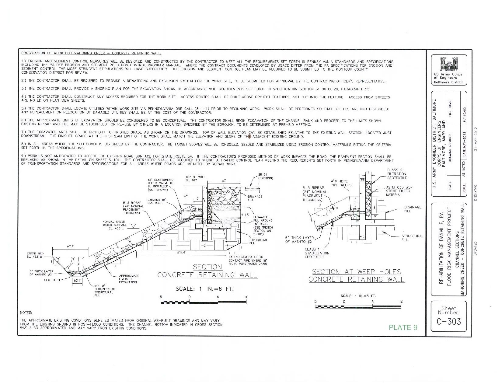
Original design
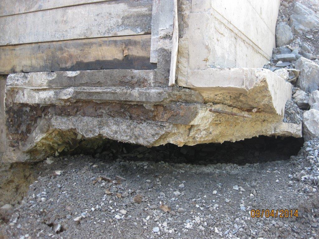
Void underneath existing wall to the south of the site
Additional limitations. Predominantly timelines…
- The Environmental Dept informed the contractor that wild trout egg stocking was to take place on 1 Oct thus the river will be in lockdown for any in-water works from 1 Oct – 23 Dec..that leaves us 3.5 weeks! Annoying that we didn’t know this as a limitation at the start (why not? I beg the question, have we got ourselves to blame?)
- The Env Dept stipulates that the dewatering scheme chosen must have a maximum lifespan of 2 weeks otherwise a new bypass system was to be designed. The contractor, without me knowing, essentially pushed himself into a corner by installing it as soon as we had approved it assuming that the E&S approval would follow shortly behind…it didn’t, it was disapproved and needed significant redesign. This put extra pressure in making any changes; some may say that is their issue/ fault – it is but we all want to get a solution in place, if we sat back, the project would fail, no funding was in place for next year and we’d be left with an open excavation, so we were all pushed into a corner somewhat!
Several conference calls later and many hours of brain-racking through options with the USACE depts of geo-tech, civil works and structures we came up with a multi-faceted solution (see pic below). The embedded original wall would be left in-situ for fear of incurring additional sedimentation, plus enabling staying on track with timelines and the consensus that it may actually help in preventing scour. The dug-toe would be removed and a new design incorporating an ‘anchor stone’ and additional reinforcing rock armour would be used (see pic), while the structural fill specification would be hastily changed from clay to a coarse gravel; this would negate the need for major dewatering and speed up time of construction. We all now have to be on the ball with processing submittals asap to meet the 1 Oct 14 hardstop. This now leaves the painful part of change orders and/or REAs but needs-must.

Slope redesign
I am pleased to say that the H&S and QC has made a dramatic turn following the insertion of the 3rd party assessor by the contractor. It is clear that morale has dived a little amongst those on site following some serious whippings, but I have no doubt they will take it on the chin and move on. It is good news, and the assessor confirmed with me that things were far from where they should be! He’ll be on site until things reach my stipulated levels per USACE specs, and then a bit longer to ensure it is maintained. He even phoned the county sheriff direct raising his concern the morning I arrived on site that some drivers were driving past at 70mph in a work zone and 35mph limit. Cue a cop-car with speed gun on site within an hour and some great viewing of law enforcement US-style in action!
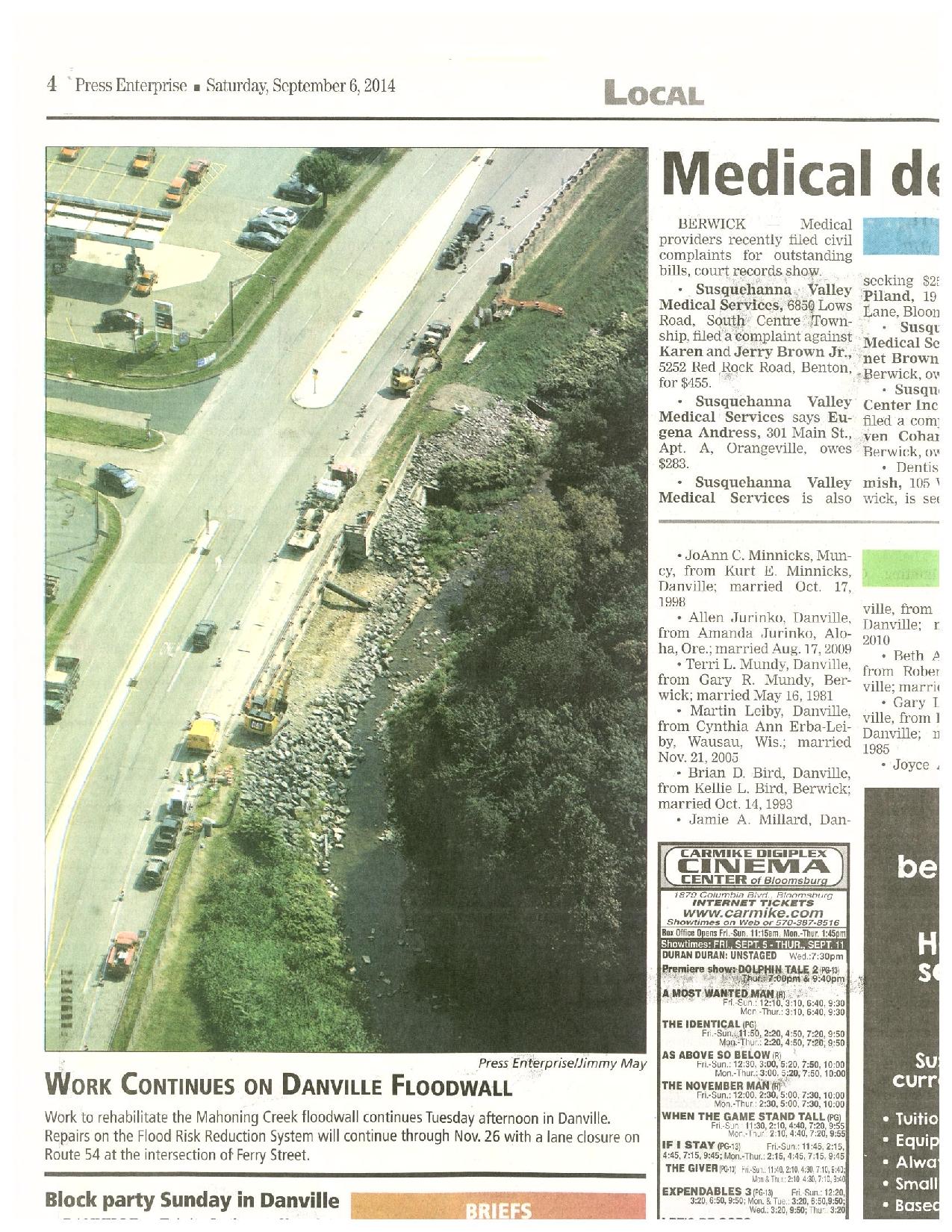
We also had a ‘congressional tasker’ (akin to the Complaints Commissioner writing directly to the CO!) …cue flapping all round. The ‘tasker’ stemmed from a Danville local writing to the Congressman on the back of a fag-packet his concerns that the project was a ‘waste of money’, because we are building the wall the same as was originally placed, and that the original wall collapsed as a result of scour to its rear. He was quite correct, but federal law (PL84) has tied our hands and dictates that disaster relief work on hydraulic related projects are done on an as-built basis. Several conference calls later, the attached letter was produced.

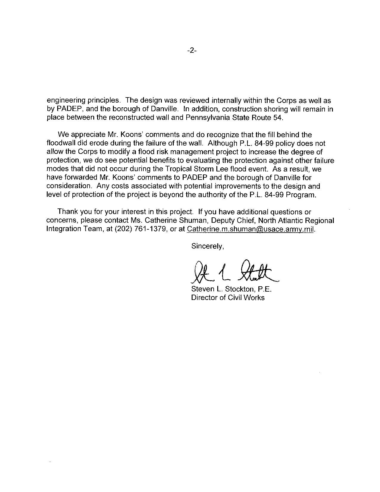
Plus, a bit of media publicity…
Also, this weekend sees the national ‘Star Spangled Banner’ celebration taking place in Baltimore’s inner harbour…100s of tall ships, Blue Angels flying displays etc – all to celebrate the 20oth year to the day from which the USA hangs its history…the first location to withstand bombardment from the Royal Navy, raising the stars and stripes for the first time, and providing the backdrop from which to write the national anthem! We will of course be attending…in a disguise of dodgy stars and stripes sunglasses and a Dunkin’ Doughnuts coffee permanently clasped in our hand; no-one will guess we’re British!? In other news, and not that we’re competing with the other HRH but maintaining the tradition of Phase 3, Emily is pregnant with our 3rd!
Depressurisation Wells
Depressurisation Wells.
During the course of the week I have been overseeing the installation of 16 depressurisation wells. From my previous blog the purpose of depressurisation wells as appose to dewatering wells is to reduce the pore water pressure, rather than stop mass water ingress into the excavation.
Situation. Although open to debate the exact reason for not completing a full depressurisation system prior to starting the excavation is not entirely clear. However the design authority (C138 Mott MacDonald) had stated the required pore pressure required before excavating below each level. From my last blog C502 (primary contractor Laing O’Rourke) are now having to install the depressurisation system 25m below the surface with only 6m clearance between the working platform and the bottom of the 89 slab level. To make the drilling more complicated, 12 of the 16 wells need the well tip outside of the contiguous pile wall, but avoiding the new crossrail tunnels running adjacent to the Blomfield Box being constructed by C510.
Soil. The soil characteristics are typical of London Clay and the Lambeth Group, over consolidated fine grain soil with laminations of course grain soils. Primarily a low permeability soil with a low voids ratio the soil is very stiff with high shear strength as a result it is extremely difficult to excavate. Added to this it is believed that at 25-30m below the current slab level (83 SSL) are the chalk and silt layers of the Lambeth Group. The risk here is the believed 40m head of the artisan water below within the chalk. Penetrating this would result in a mass water ingress and flooding of the Blomfield box, a potential risk to the project and to life.
Drilling Rig. The drilling rig being used is a Berretta T 57 Geo, which usually has a 10.5 m fixed mast. Given the high strength of the soil, the possibility of pile overspill the drill and the restricted head room the drill was modified rather than use smaller drilling rig with insufficient power to penetrate the soil efficiently. In addition the drilling rig would need to be articulated in order that it could drill at an angle to allow the well tips to be outside of the pile wall. As a result the drilling rig had a smaller mast at 5.5m and hydraulic rams to adjust the drilling angle fitted, all of this was completed in Italy at the expense of C502.
Depressurisation Wells
The well system being used is an ejector system that uses a vacuum to reduce the pressure within the well to set up a artificial low pressure and hydraulic gradient which is intended to draw the porewater from the soil and reduce the pore pressure. The low permeability of the soil means that the seepage rate of the soil is not sufficient to lower the porewater pressure to the required levels set by C138. Unlike an air induced vacuum as used on deep well systems the ejector system induces a vacuum by pumping water into the ejector well tip which sets up a venturi vacuum. The amount of water that is extracted must account for the water pump through the ejector to set up the ventral vacuum.
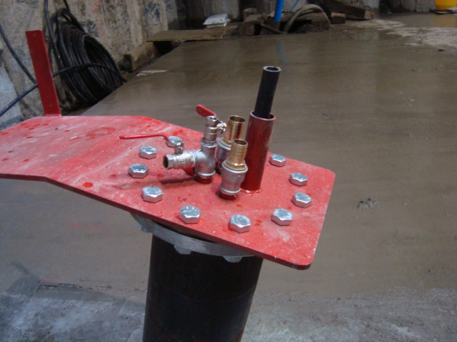
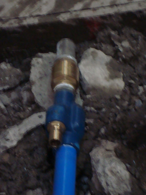
Pictures Right to Left, Well head showoing water inlet and outlet, ejector pump head, water injected through left connection, water removed from main blue pipe.
Drilling Operation.
Angle of Attack. In order to place the wells outside of the pile wall we determined the end location of the wells at 65m, and the location of the C510 running tunnels at 72/73m. This gave us a angle of between 15-20o and at a distance of 2.2m from the pile face.
Drill Setup. As the engineer overseeing the drilling I have been setting up the drilling points and then confirming the drill is at the correct angle prior to drilling. This has been done by using the EDM to determine the Easting and Height of two points on the mast, then using Trig to determine the angle of the mast.
Drilling speed . The speed of drilling is governed not by how fast the drill can be forced through the soil but how quickly the cuttings can be cleared from the well. The drill uses a drilling tip and drilling rods using drilling mud to bring the cuttings to the surface, not an auger.
Drilling Mud. Drilling mud is a mixture of water and additive to create watery slurry. The type of additive used is dependent on the soil type. The drilling mud acts as; a lubricant for the drilling tip, as a well filler similar to bentonite to maintain horizontal pressure to keep the well open and as medium to carry the cuttings clear of the well. Drilling mud is pumped through the centre of the drilling string to the tip, it then picks up cuttings and is forced to the surface. The drilling mud then passes through a series of settlement tanks and then recycled. The types of addictive for different soil types are not an area that I have a great deal of information at this time.
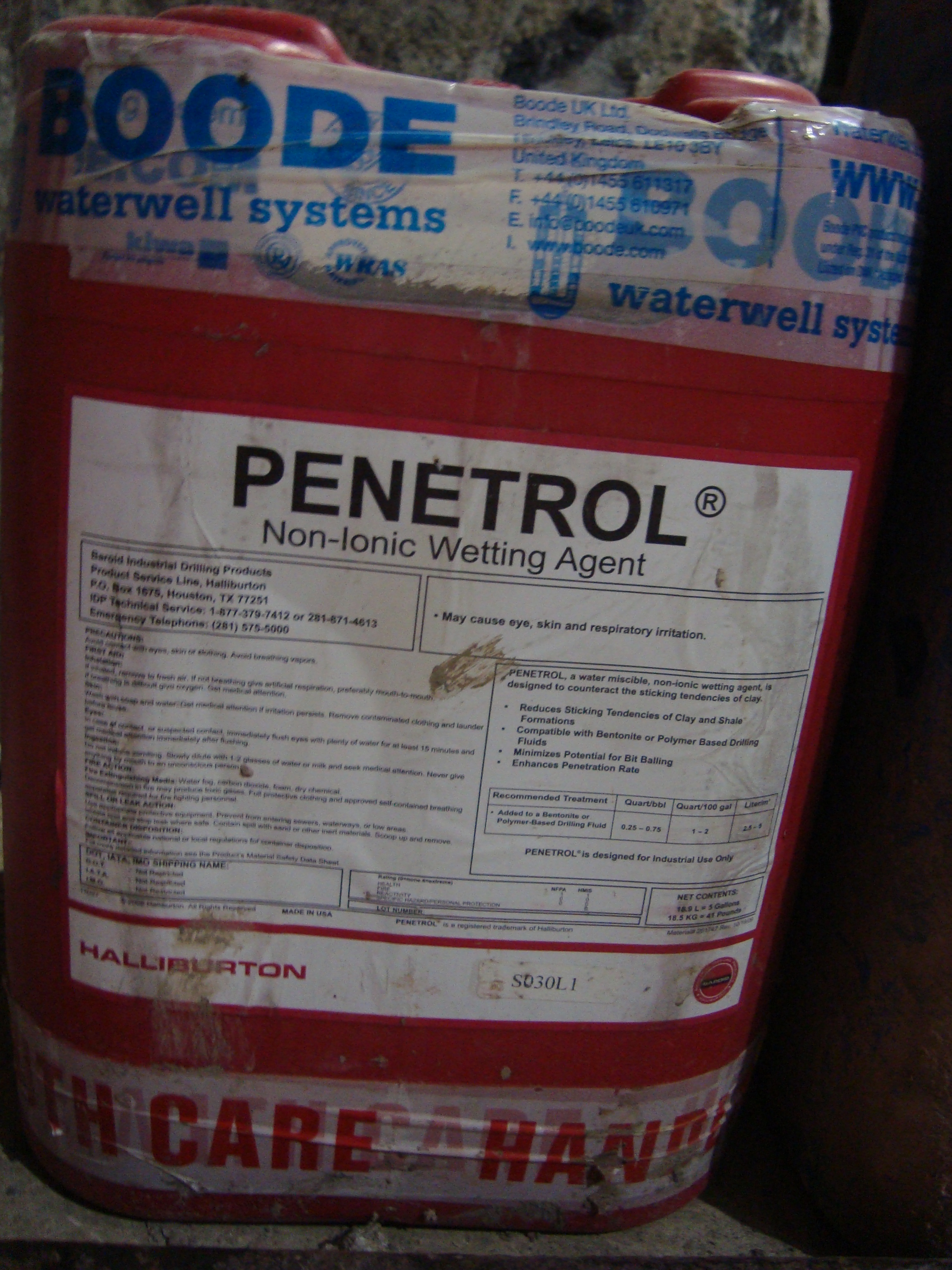

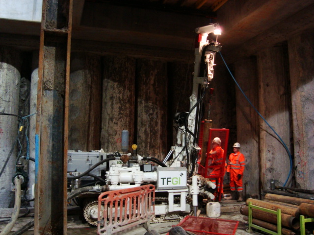
Pictures Right to Left, Drililng mud additive, Drilling rig set at 15 degrees, drilling rig
Another Big Lift
This blog will not add any value by recording reflections but it is one I thought might be reasonably interesting given Peter’s enthusiastic reaction to my last big lift photo in blog 7, DO heaven.
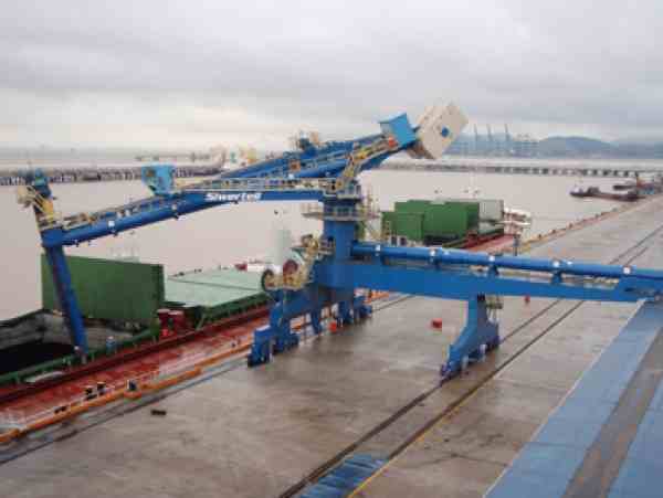
This is one of two 600T £7M Siwertell Container Ship Unloader’s (CSU’s) designed in Sweden, constructed in Italy and delivered to Immingham last week, being lifted off the transport ship by the two on-board 400T cranes. The whole operation went well and the ship off loaded the 2 systems and all ancillary parts in 3 days before departing a day ahead of schedule to Amsterdam (who wouldn’t?!).
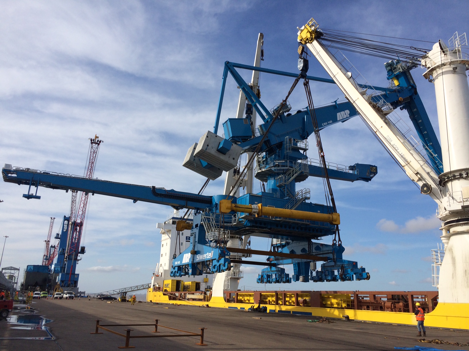
CSU No 1 is lifted from the hold.
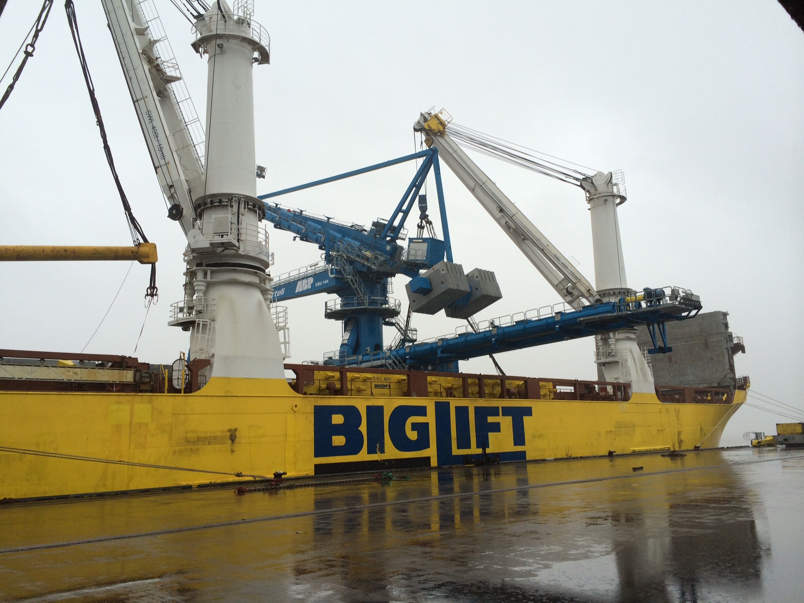
CSU No 2 is prepared for lifting.
These are quite interesting pieces of engineering and are based on the Archimedes Screw principle designed in the 3rd century BC. The rail mounted screw conveyor is an Archimedes screw contained within a tube and turned by a motor so as to deliver the biomass wood pellets from the ships hold to the conveyor system leading to the RC storage silos. This dramatically reduces the amount of labour, energy, spillage, explosive dust and importantly discharge time when compared to the conventional cranes. Whilst initially expensive the discharge time is effectively halved meaning double the amount of biomass ships can be unloaded in a given time increasing ABP’s profit. I expect that they will pay for themselves in a reasonably short space of time. Whilst the image below from Siwertells website is not the greatest quality it shows exactly how the system works.
Due to my discoveries during the trail hole excavations at the sub-station there has been a delay whilst the redesign takes place and thus the CSUs have become my focus for the last week or so. This has involved a number of snagging type tasks from clearance and inspections of the rail lines that the CSUs will travel on through to the positioning, drilling and placing of the storm locks and rail clamps that guide the CSU and secure them during a North Sea battering.
