Archive
A job with a view!
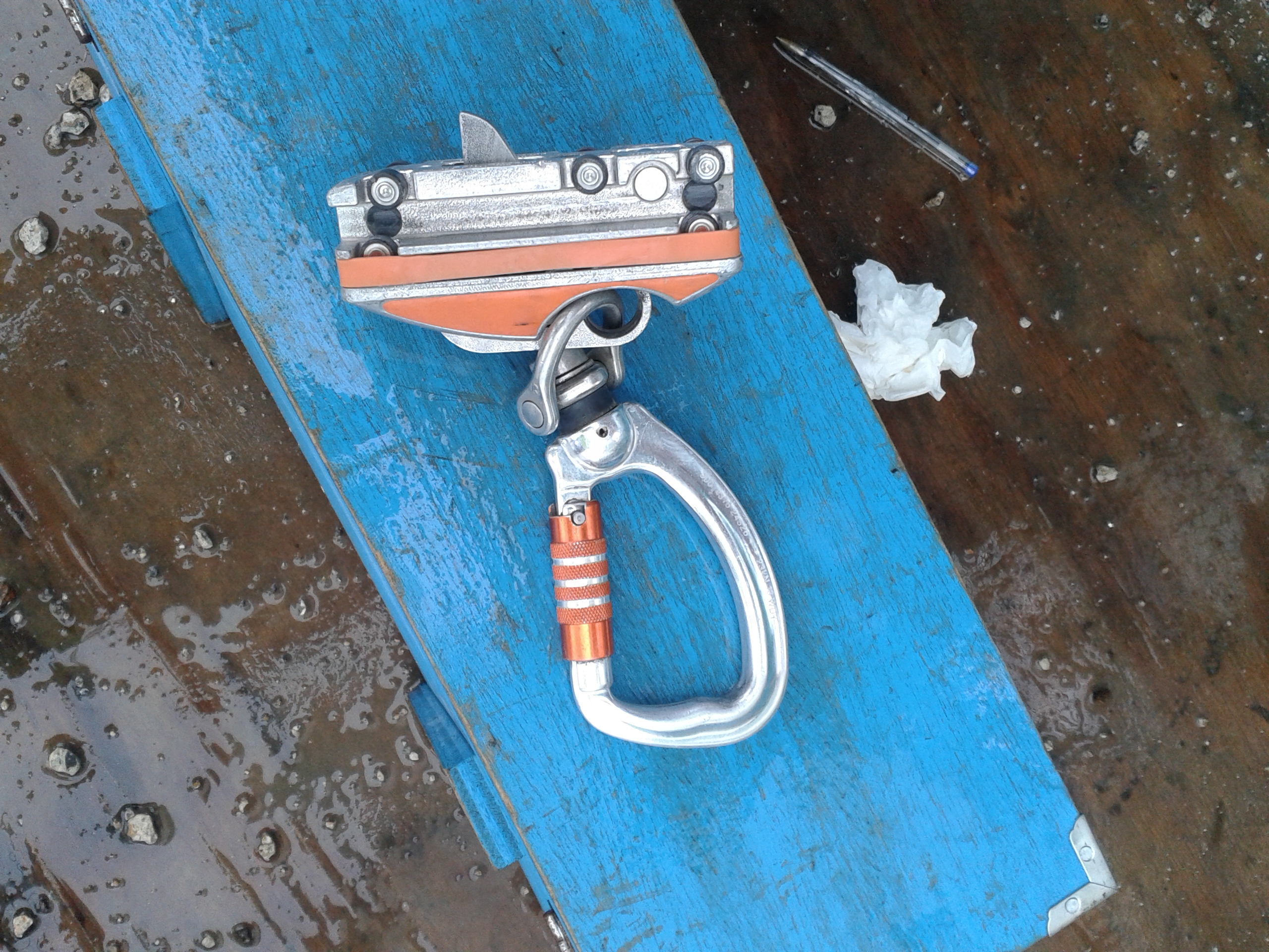
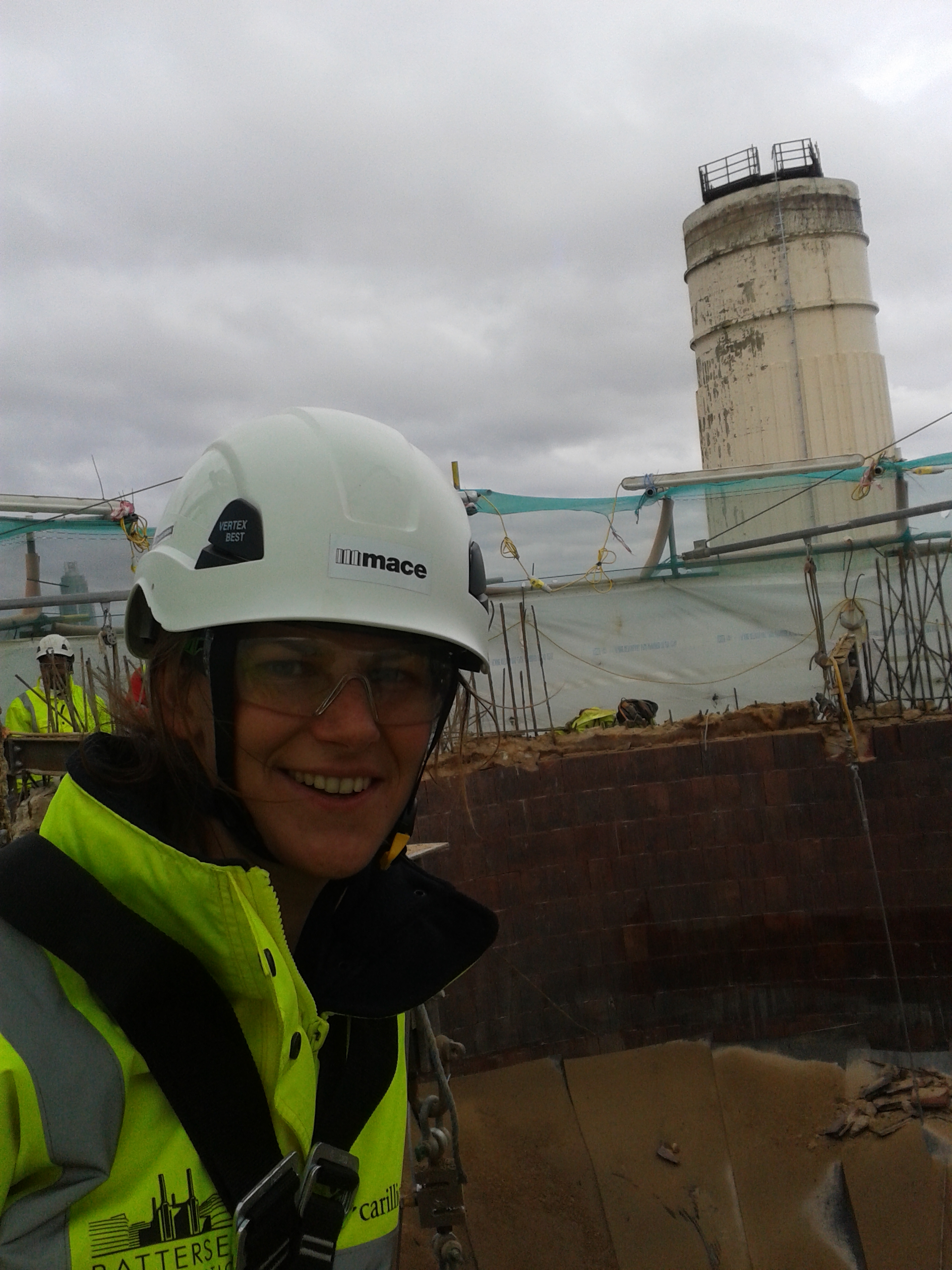
I finally managed to make a contact over in Mace by randomly chatting to the Project Director on the walk to site. He put me in touch with one of the engineers to chat about some of the technical issues who then put me in touch with a construction manager to organise my trip up a chimney! Having told him that I was a climbing instructor he quite happily gave me a full body harness and a glide-lock fall arrester off we went on a nice windy day!
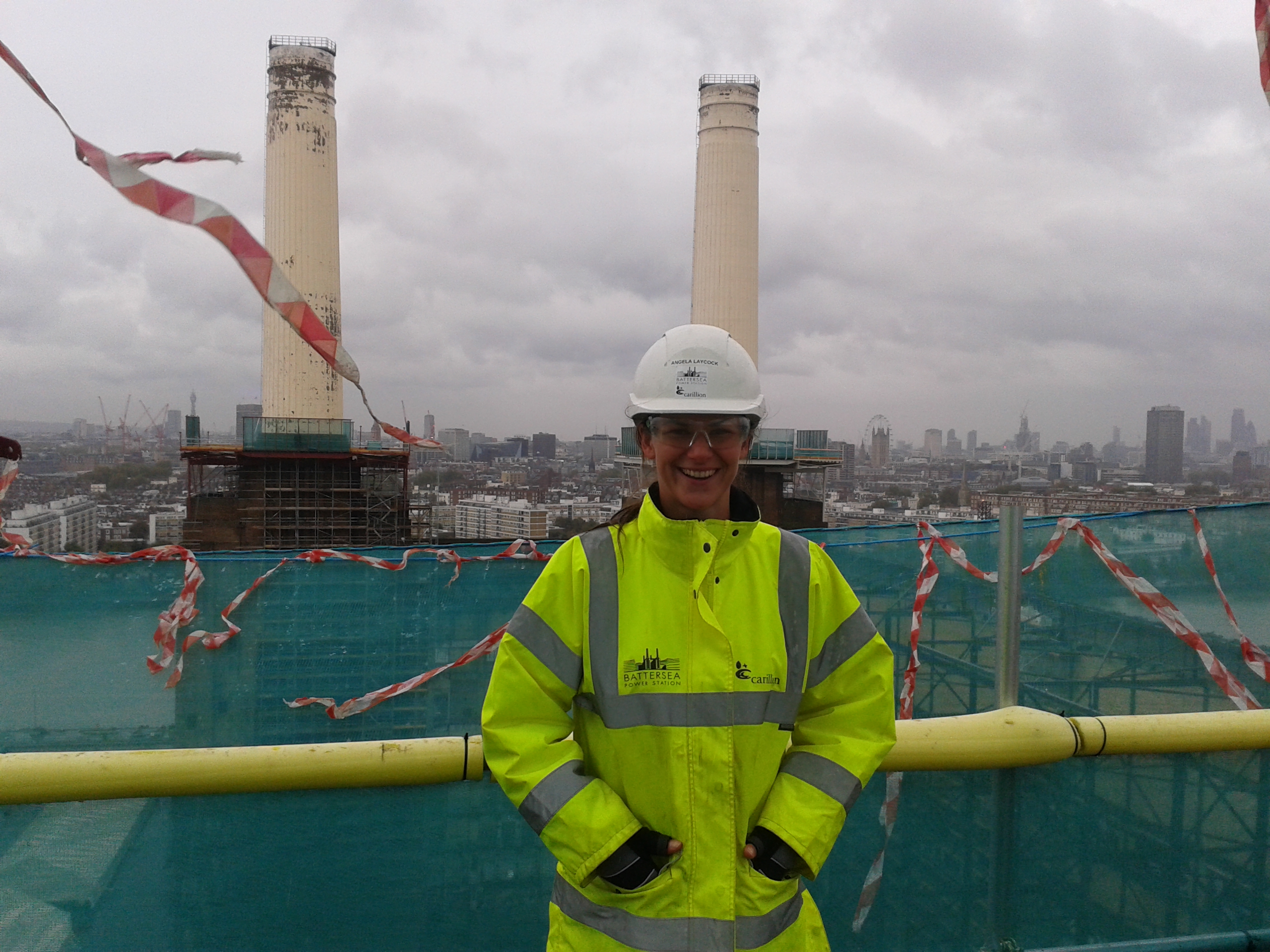
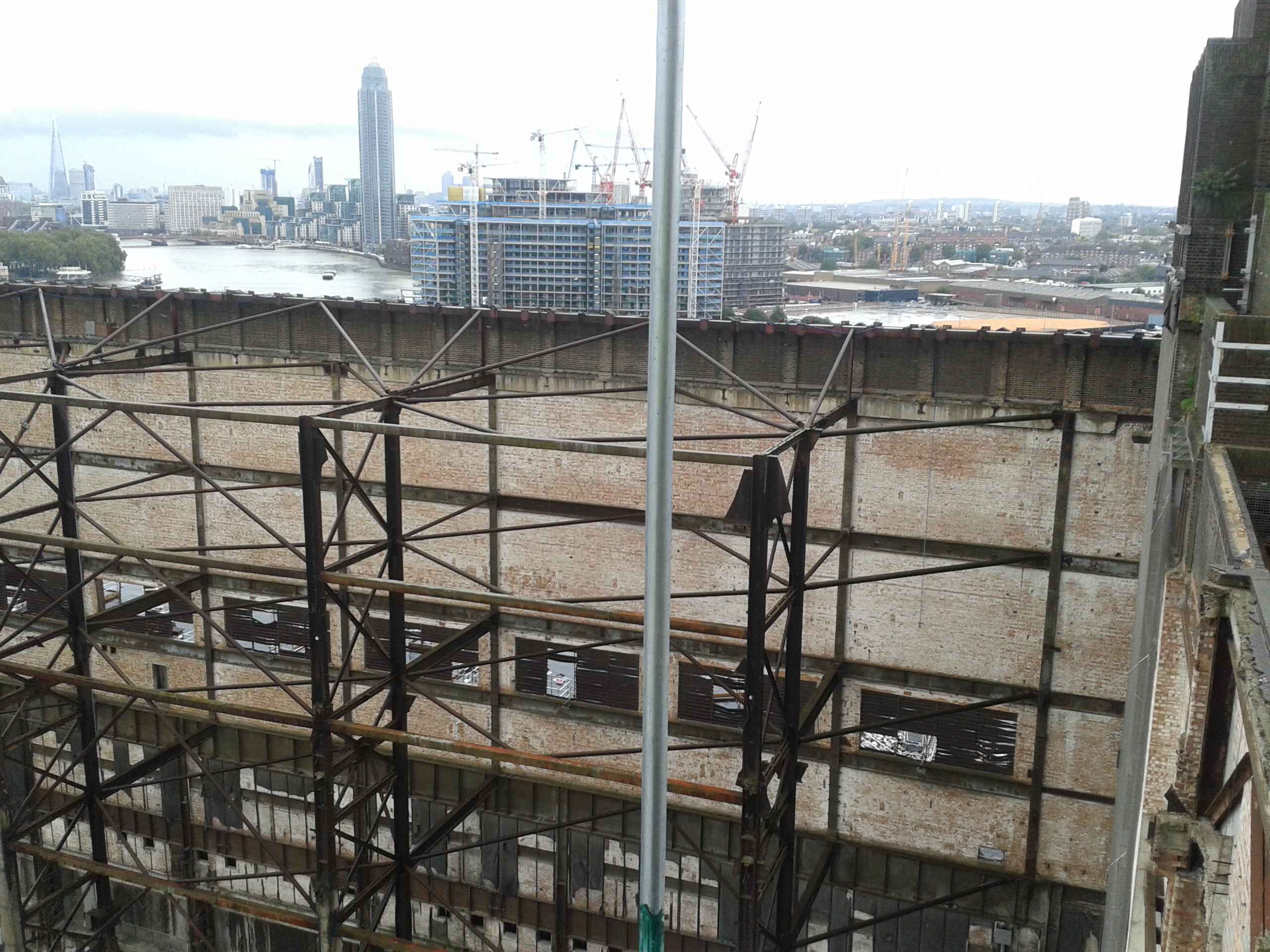
To get up the chimney you first catch the hoist up to the 14th stop which takes you to a level of scaffolding around the top of the brick wash tower. From there you climb up a couple of platforms via ladders until you are on the large protective platform that is designed to contain any spoil which falls from the demolition of the chimney. Even from there the view is pretty good and you can see what remains of interior of the steel framed-brick clad building.
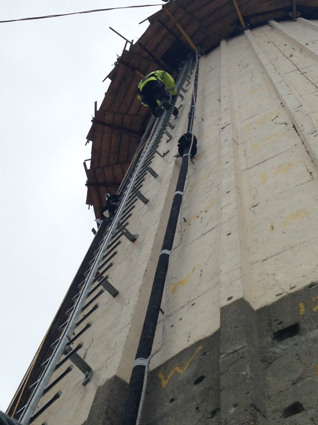
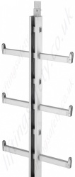
If that wasn’t enough to trigger a bit of vertigo, the really exciting part comes next with the ladder of doom. The only access to the top of the chimneys is by a “Y-spar” ladder that has been bolted into the good bits of concrete. It wasn’t quite as hairy as the Via Ferratta on the Camino del Rey in Spain but it certainly got the adrenalin going!
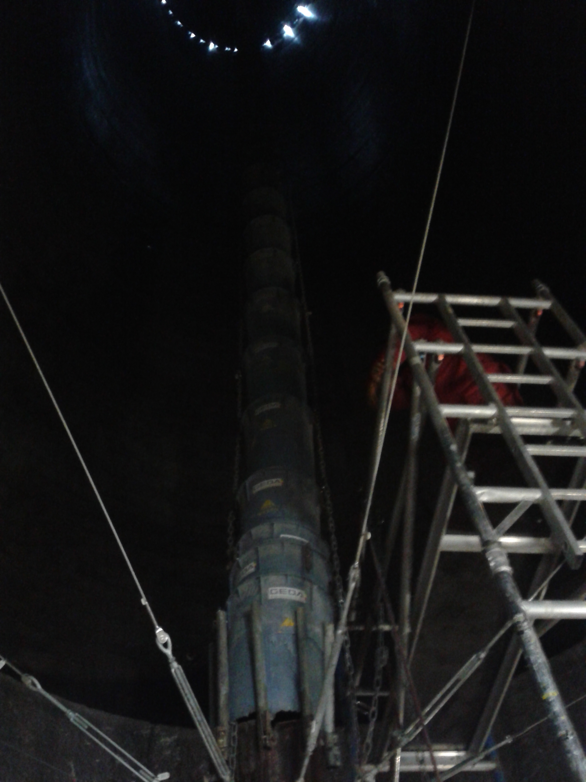
At the top of the chimney they have two circular platforms which can ‘climb’ up and down the chimney using hydraulic actuators on the bottom platform. They act as compressive bands around the chimney providing support keeping the concrete in compression. Hoists and other access methods were not used as vibration and differential loading could cause the 80 year old concrete to continue to crack and spall. Prior to the breaking of the concrete the interior of the chimneys was sprayed with a sealant to prevent the tiles which line each chimney falling off and to seal in any contaminated particles. The original plan was to use hydrualic concrete breakers on Davit arms on the top platform to crush the concrete and the reinforcement was to be cut using hand tools. The broken pieces were caught in the centre of the chimney in a collection funnel which then travelled down the centre of the chimney into the building. The pictures below show: 1) the breakers, 2) the chimney rebar, tiles inside the chimney and top of the collection funnel, 3+4) the funnel chute inside the chimney.

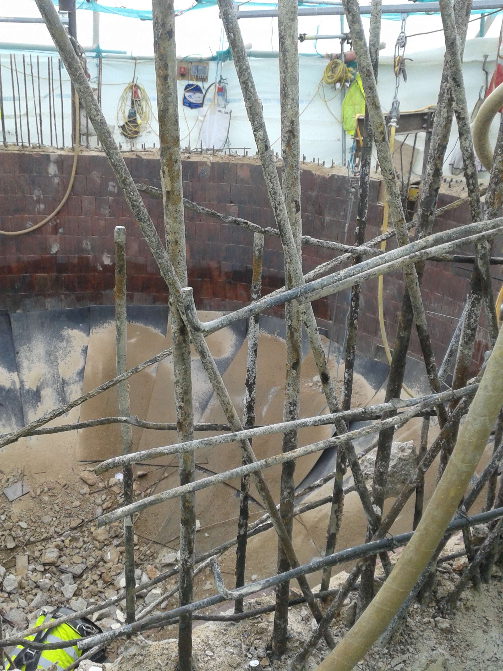
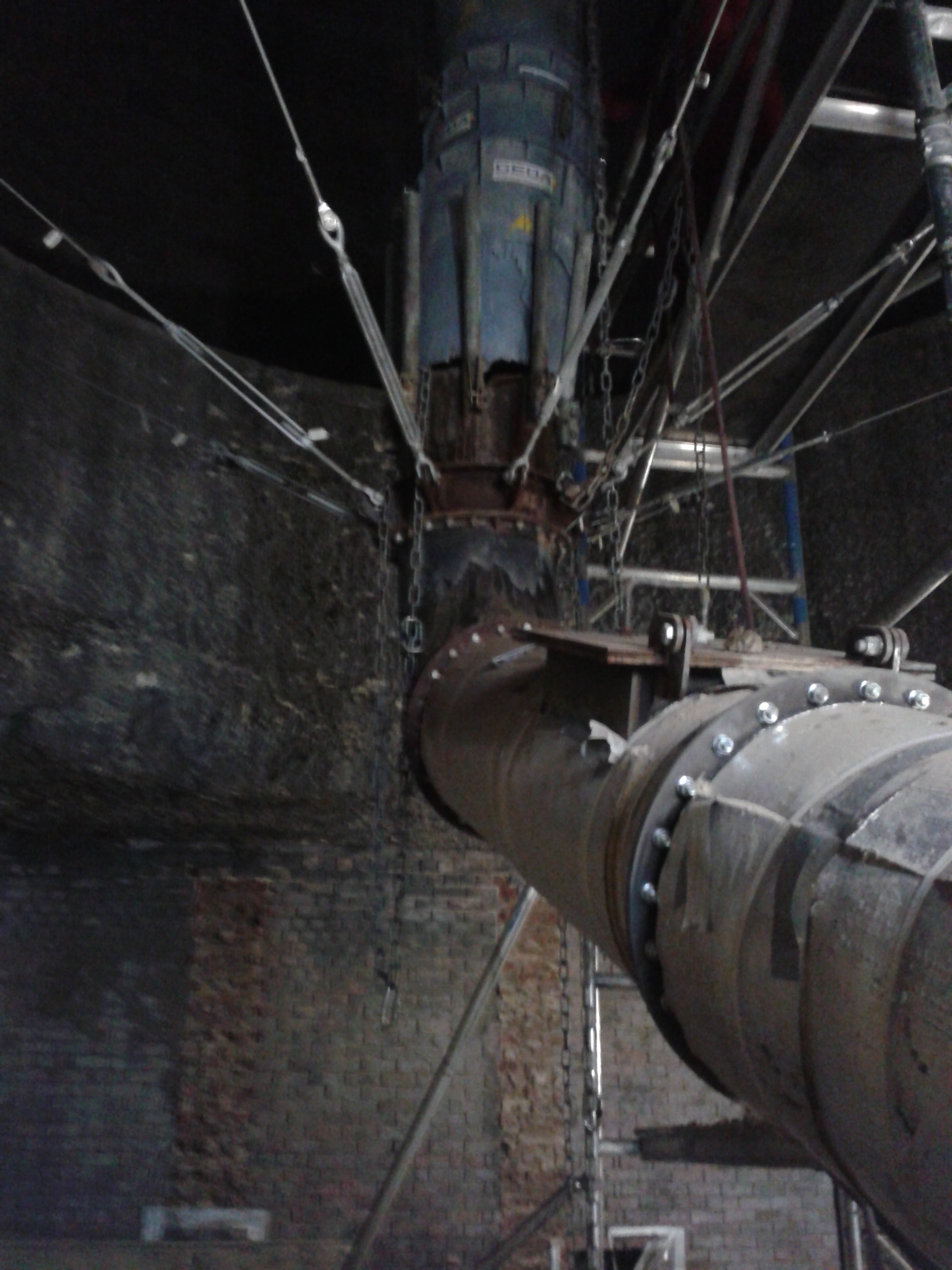
The dense lattice reinforcement meant that the breakers did not work effectively and the concrete did not separate from the rebar easily. The process was proving to be too slow so they switched to using pneumatic hand breakers and circular saws to break the concrete and cut the rebar. The process is quicker but more operatives are required due to the time limitations on the equipment due to the risk of HAVS.
The chimney will be demolished until the final section where the client want to keep a full section for display. It is yet to be decided how this will be achieved! The chimney will then be rebuilt using the jump form technique in 1.2m (4ft) sections to achieve the same ‘day lines’ as the original chimneys. The paint has already been matched and a small concrete batching plant inside the building will be used to produce their own concrete. Once they have built 25m of the first chimney, they will have the planning permission to continue with all 3 of the other chimneys concurrently as the cost and methodology will be proven. They are already looking into other forms of mechanical breaking rigs for use on the other chimneys to speed up the process and reduce the use of hand held equipment.
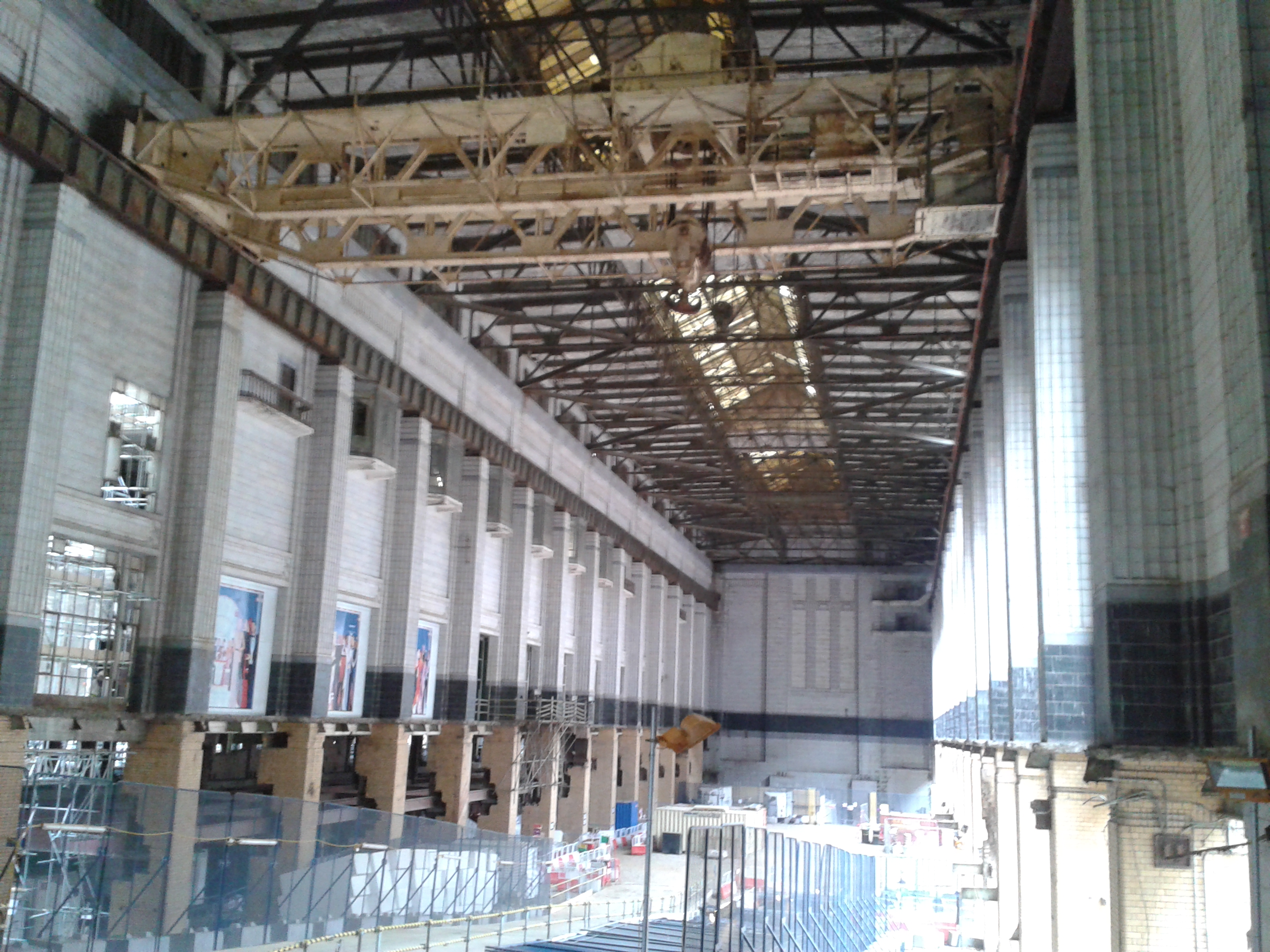
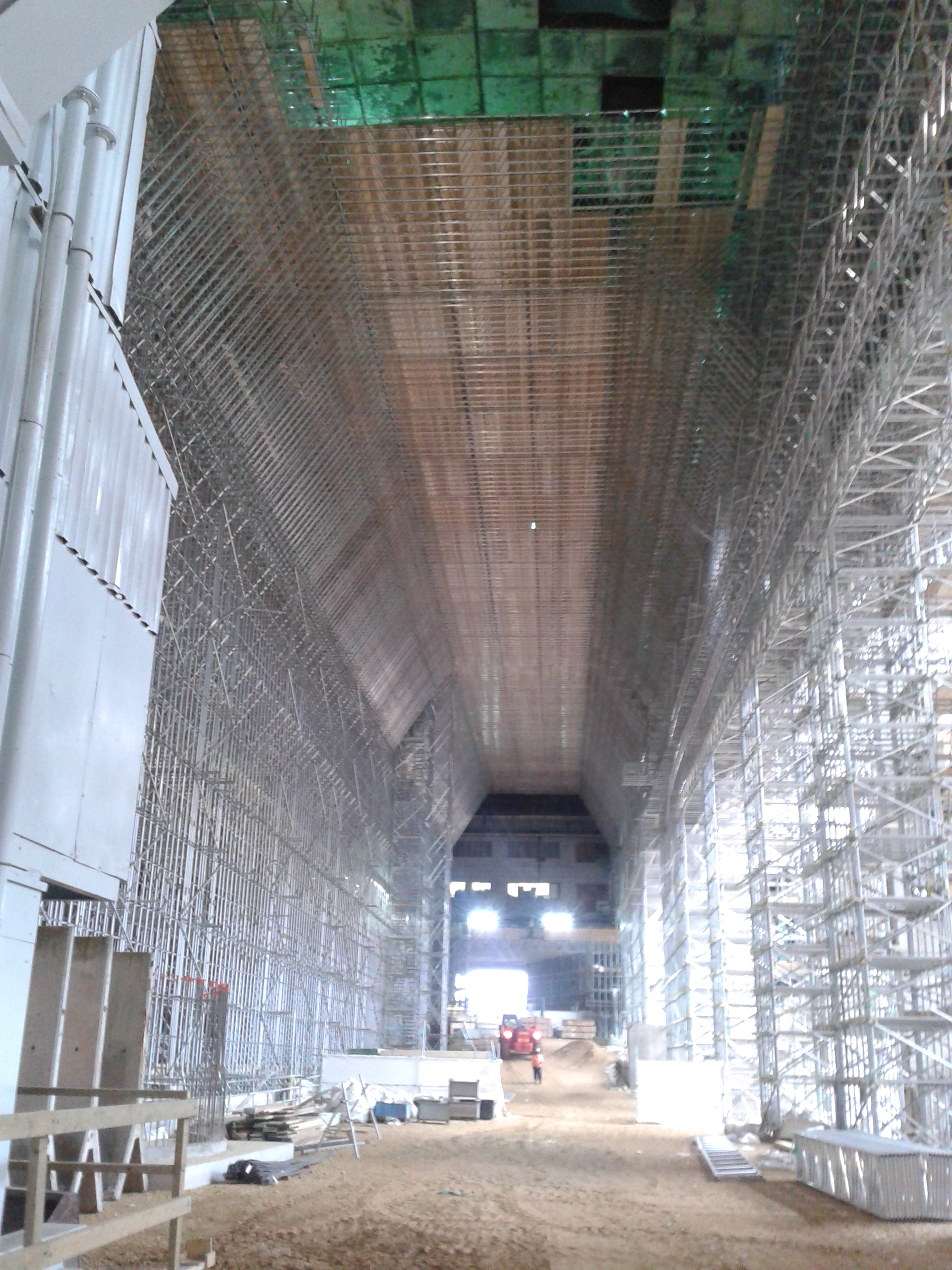
I was also shown around the main turbine halls which will be being refurbished. The asbestos has been removed and work has started on erecting the scaffolding to repair the roof. Even that is an impressive structure that I would not like to do the temporary works design on!
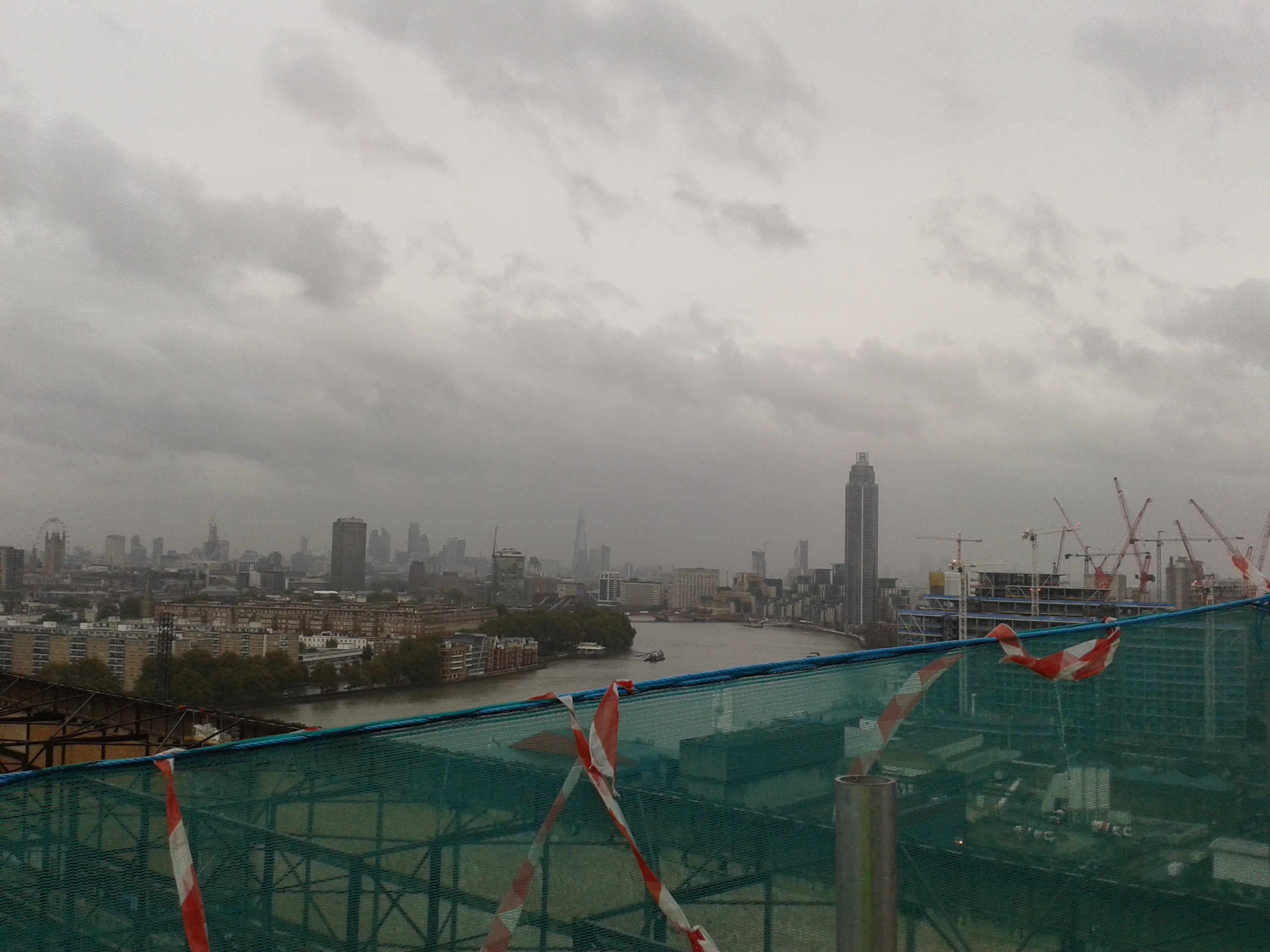
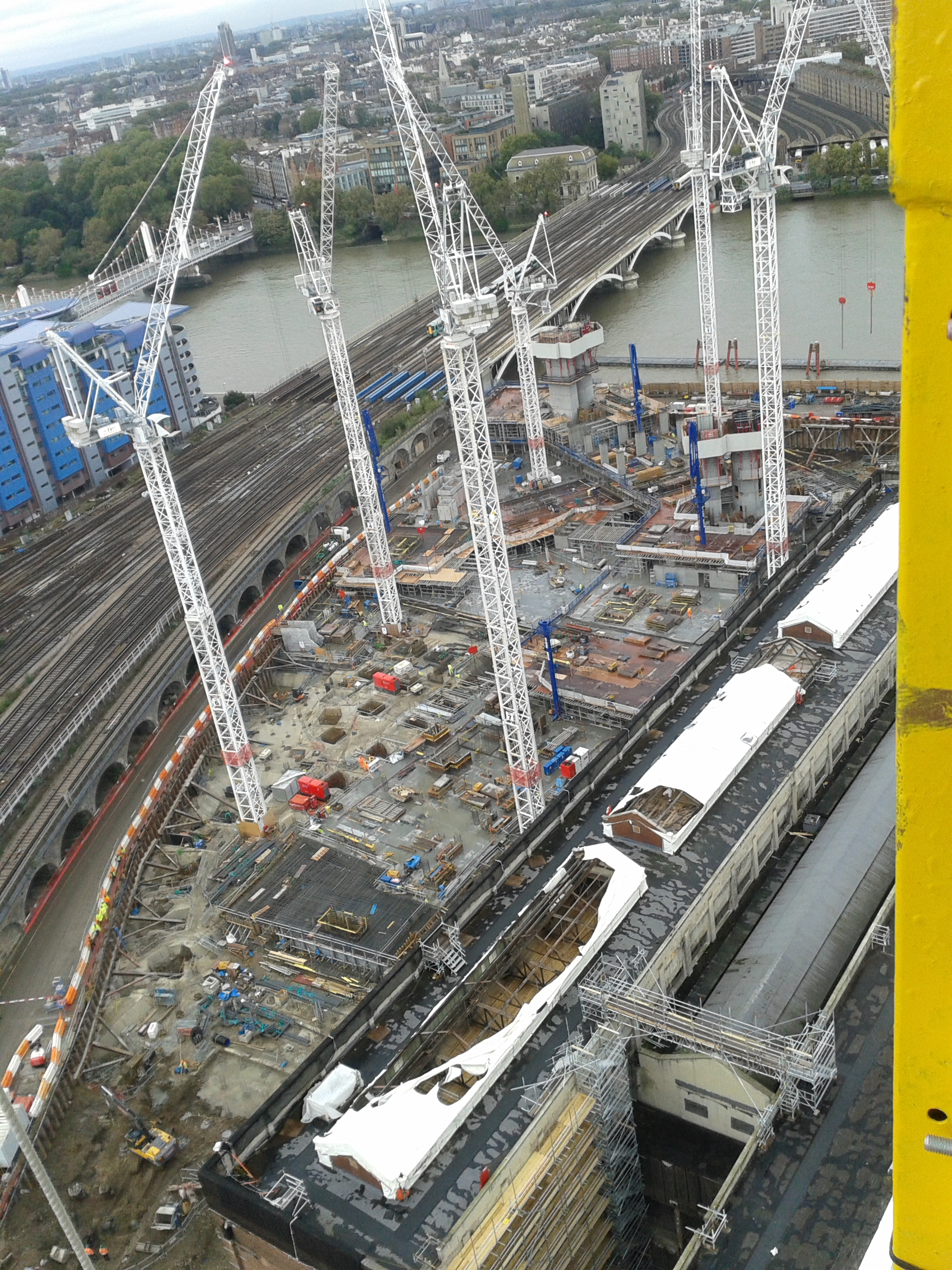
The trip up the chimneys also provided a good vantage point to view our construction site with Block G looking like Ex Cofferdam and my Network Rail Road standing proud along the main site.

Back to the real world and my construction site. Well we hit a major milestone with the HV being switched on the other week-only 6 months later than planned! We are also near to getting the approvals for the microboring so work is likely to commence in the next couple of weeks. We also found out today that the Northern Line Extension contract has been signed by Laing O’Rourke and they have designed their escalator shaft to go straight through our HV cables, water supply and comms ducts despite them being a constraints drawing showing them! I think this project will be trying to dig up as much of the previous phases as they can as co-ordinated design doesn’t seem to be their strong point!
JHG learning from others!!
Information Communications and Technology (ICT)
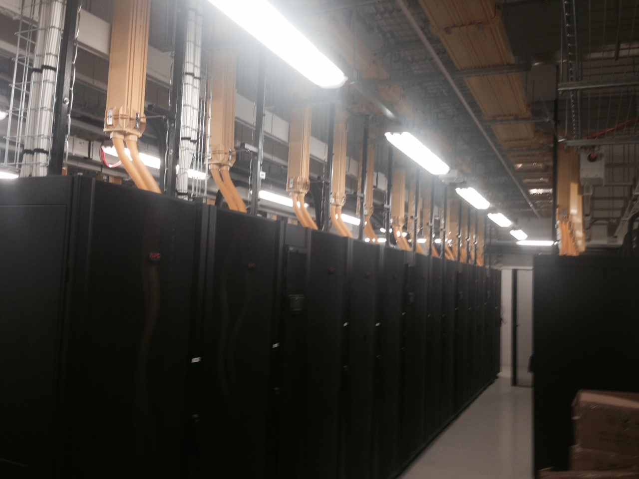
The Fiona Stanley Hospital which is also a hospital built in Perth was completed in December 2013, it still has not open due to the ICT packages a State deliverable not functioning properly. This has been one of my major focuses for the past 6 to 8 weeks, ensuring we (JHG) deliver the ICT package early enough to the State to enable the State to have sufficient time to make Perth Children’s hospital (PCH) work. My main focus has been on the Central Communications Room 2 (CCR 2) and having it ready for commissioning on the 25th November 2014, which has involved all subcontractors from looking at UPS power, Critical Essential power, in row cooling, leak detection, fibre optics, copper cabling, earthing system and quite interestingly a carbon based anti static flooring. Which is has is a black carbon based primer which is the medium to conduct electrical current through it with a number of specific earthing points.
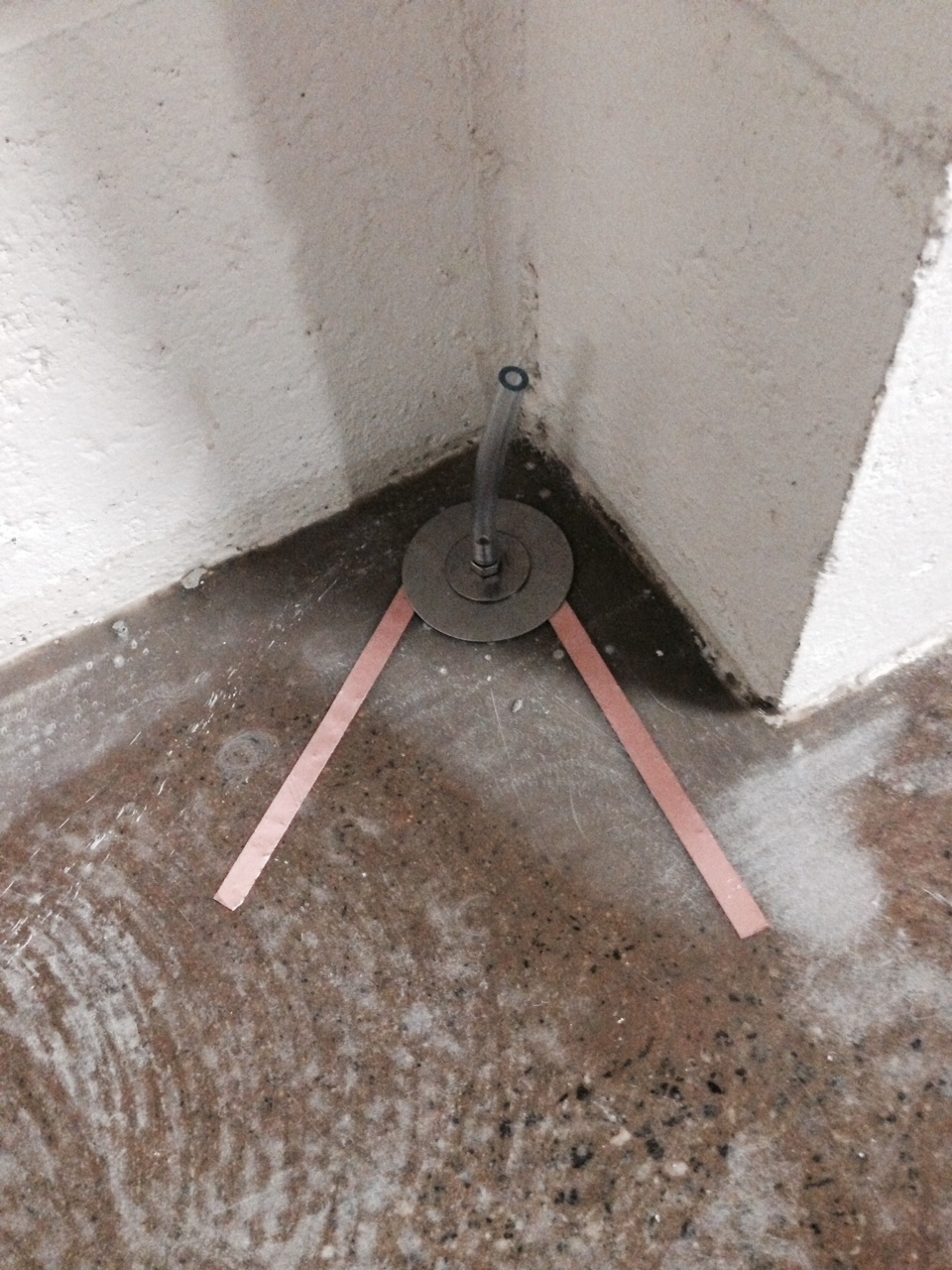
This system uses small copper strips and a conductive flooring which is a new system, compared to that of the existing systems which involved a full grid matrix of copper foil to interlink all the floor. The next phase is then pour and rolling the carbon based conductive flooring which is roughly 2-3mm thick and then do a physical test which is meant to represent the pressure of a foot and ensure the floor is conductive see photo below.
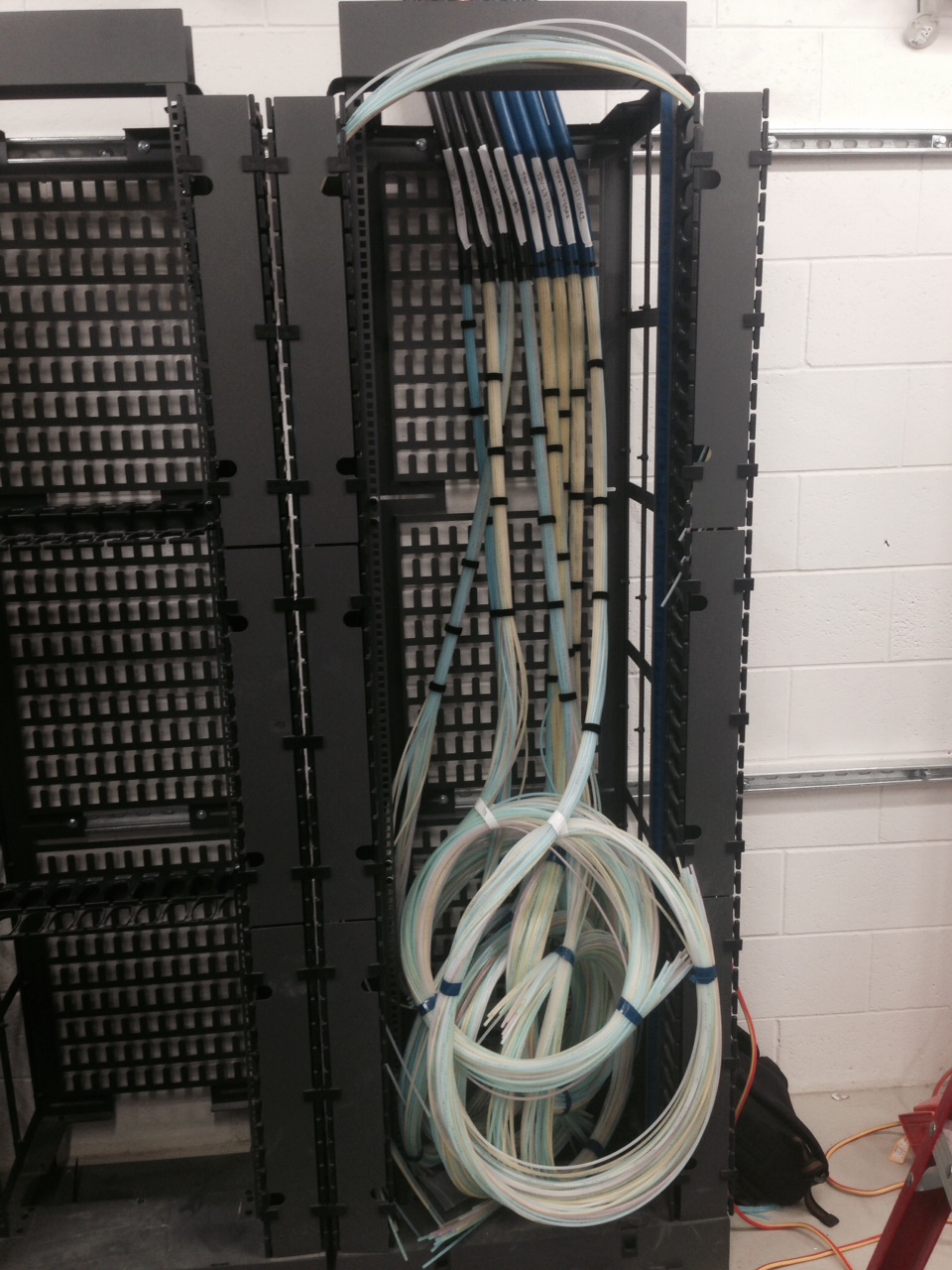
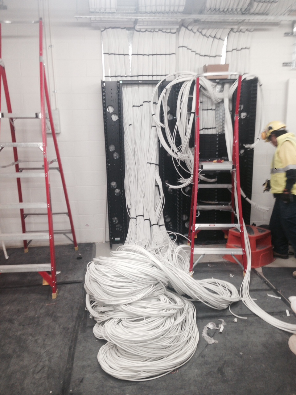
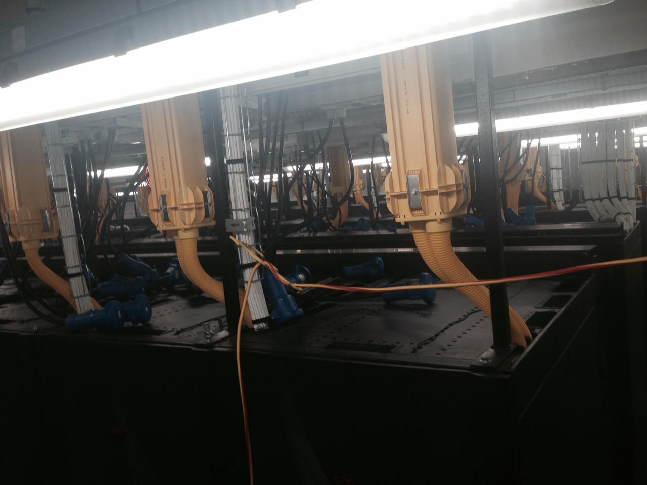
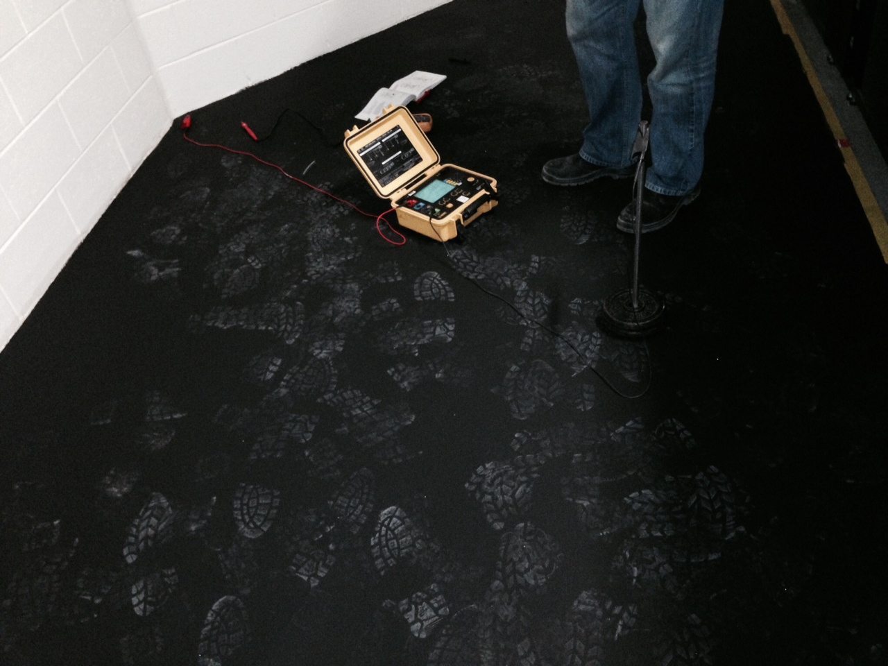 Quite an amazing product made by Sika the German paint company, I conducted the testing with Tercel the earthing company and it was an interesting experience. Below are a number of photo’s of CCR 2 including blown fibre tubing, copper interconnect cabling and all the electrical works to power the racks.
We have Power!!
On the 15th of September HV power was connected from the Central Energy Plant to the hospital a huge and extremely significant milestone for the project, this was the first piece of work which I worked on when starting the project. It involved a weekly meeting, factory acceptance tests of all LV main switch boards, air freighting equipment in from China and lots of hard work. It was delivered only two days after programme so a huge achievement by all involved. I have learnt a great deal about HV and the switching process and also Australian Standards on safety equipment and earthing.
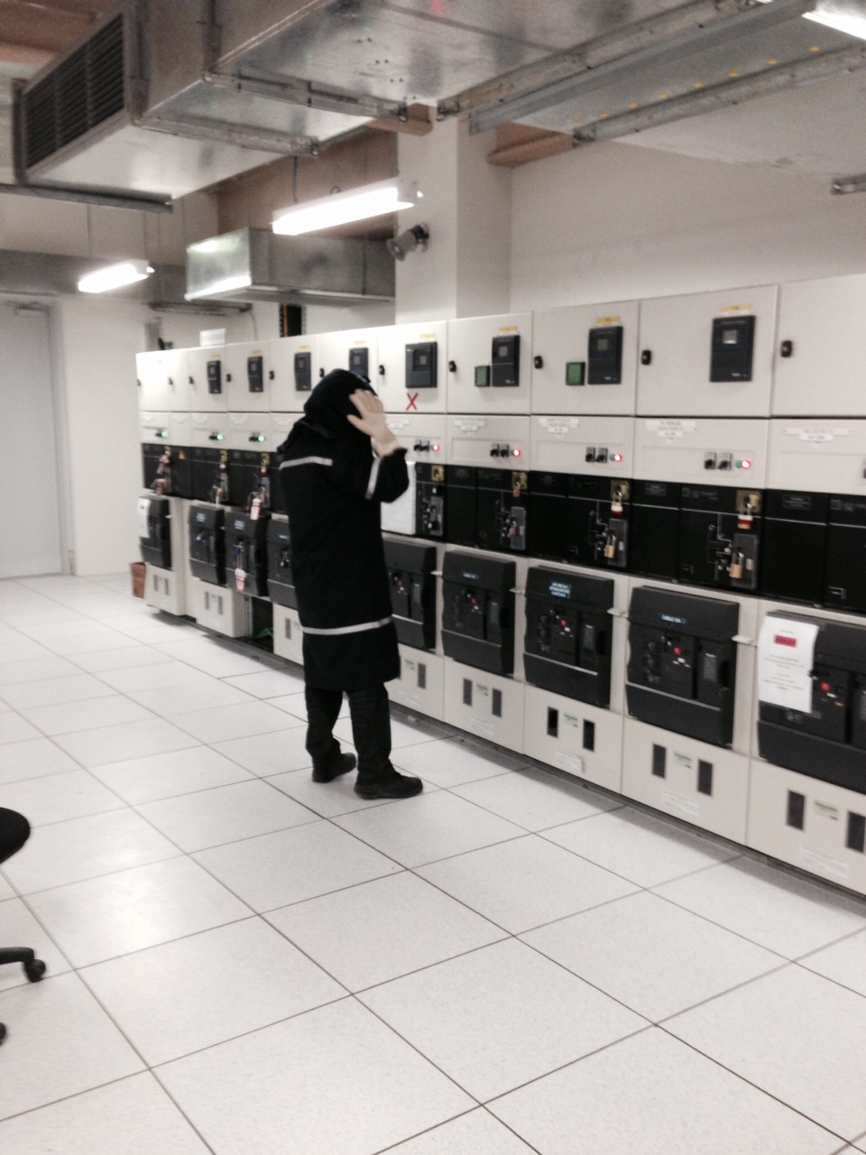
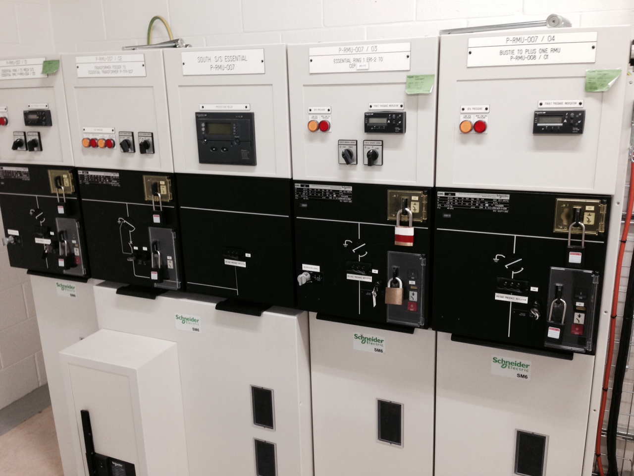 The first part of the process after everyone was content that everything had been completed, all the inspection and test plans had been signed, was locking out of all the HV switch gear in PCH, then with coordination to ensure all HV rooms where clear of people the switching process began. Photo below show the actual switching on of PCH from CEP.
Mechanical subcontractor troubles
With continued trouble with the mech subbie, with no thought into how the large diameter pipework is being restrained caused a huge amount of problem, when they finally designed there support system and it was entered into the BIM 360 construction model. It meant weeks of modelling to get clash free before installation could proceed. This battle has continued with lack of documentation for welding certificates in line with the specification and the latest item which I have been investigation is all their commissioning sets being dramatically undersized. Looking at BISRA, CIBSE and the manufacturing guides lines valves on occasion where two or three sizes too small. See photo below for an example.
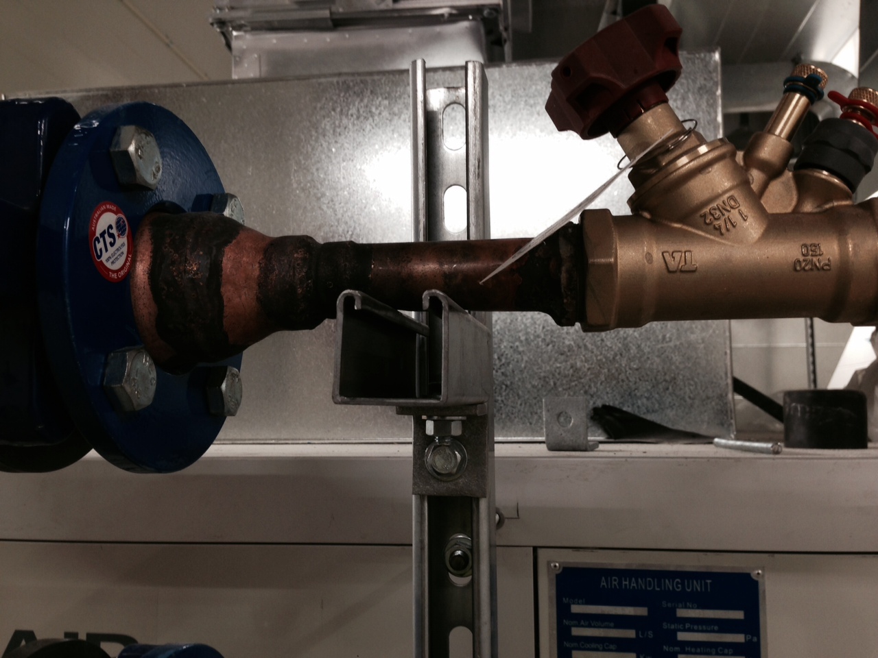 The pipe diameters where dropping from 65mm pipe to a 32mm commissioning set as can be seen above and the location of the commissioning sets and motorised valves are located to close to elbows, pipe reductions or locations which would cause irregular flow which would ultimately effect balancing and commissioning. The mech subbie now sadly takes up a large amount of my time due to the determination to cut corners, not build as per specification and proceed in areas which have not been coordinated correctly.
Aussie Living
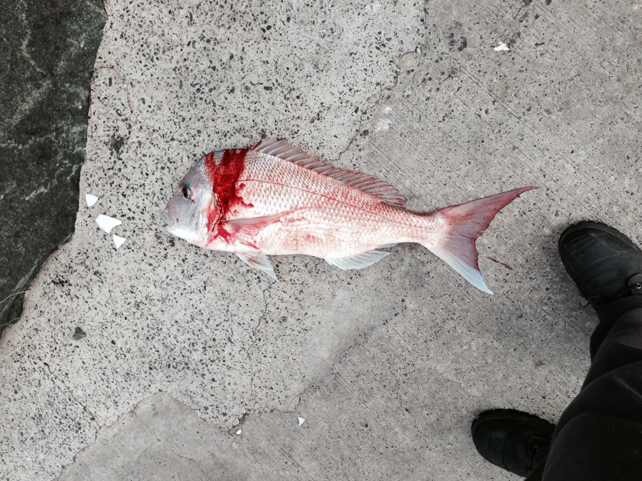
On a positive note I am now swimming for a local club and will be going to the National Masters competition in Hobart Tasmania, Hannah has entered us both into a half Ironman in November great joy!! Hannah is also doing trails with the Australian Modern Pentathlon team. I am also still fishing 4.5kg snapper below and kiting when I can.