Archive
Riyadh Metro – Ground Water Risk, again!!, but different!!!
Now at the end of my second week with Arup I have found a desk, computer and even taken some time to find the library check out some books and remind myself what a bending moment is. Not sure why I am surprised but a have found copies of most the books we were issued on course either in the library or actually being used by engineers around the office.
I have been assigned to the Riyadh metro team and once again find myself looking at trains underground.
Project in brief
The Riyadh Metro is part of a wider scheme to regenerate the public transport system around the capital city of Saudi Arabia called the Riyadh Public Transport Project (RPTP). The metro system is to be a rapid transit system designed to reduce congestion within the city due to the rapid growth in the size of the population of Riyadh within the last 10 years. Construction of the metro system began in April 2014 and is due to be completed in 2018.Once completed the Riyadh metro consist of six lines totalling 178km of track and 85 new stations. Arup have been employed as lead design consultant by BACS consortium consisting of Bechtel, Almabani General Contractors, Consolidated Contractors Company and Siemens. At Arup the Riyadh metro team is responsible for the design of the five subsurface stations along the Green and Blue lines. At my time of arrival the 30% concept design has been completed and the team are now turning their attention to the 60% detail design phase. I have been assigned to the team looking at station 1F2 which is considered the most complex of all the stations. The complexity is due to the interface of already existing buildings, a main highway (under which the station is to be built), a flyover and testing ground conditions.
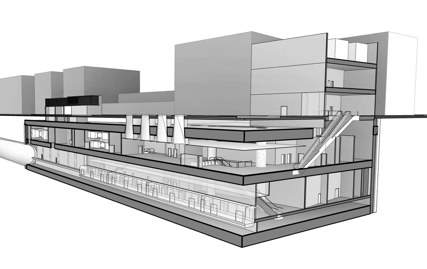
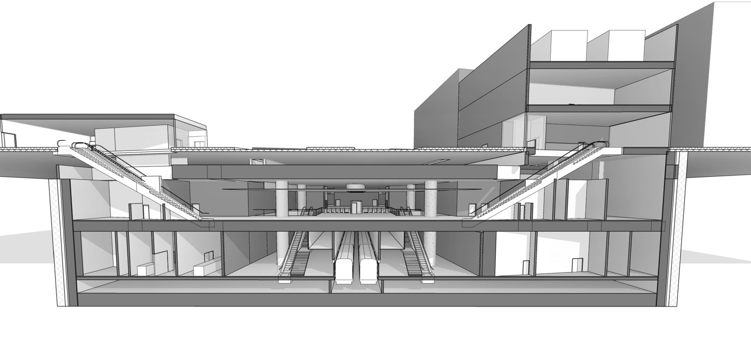
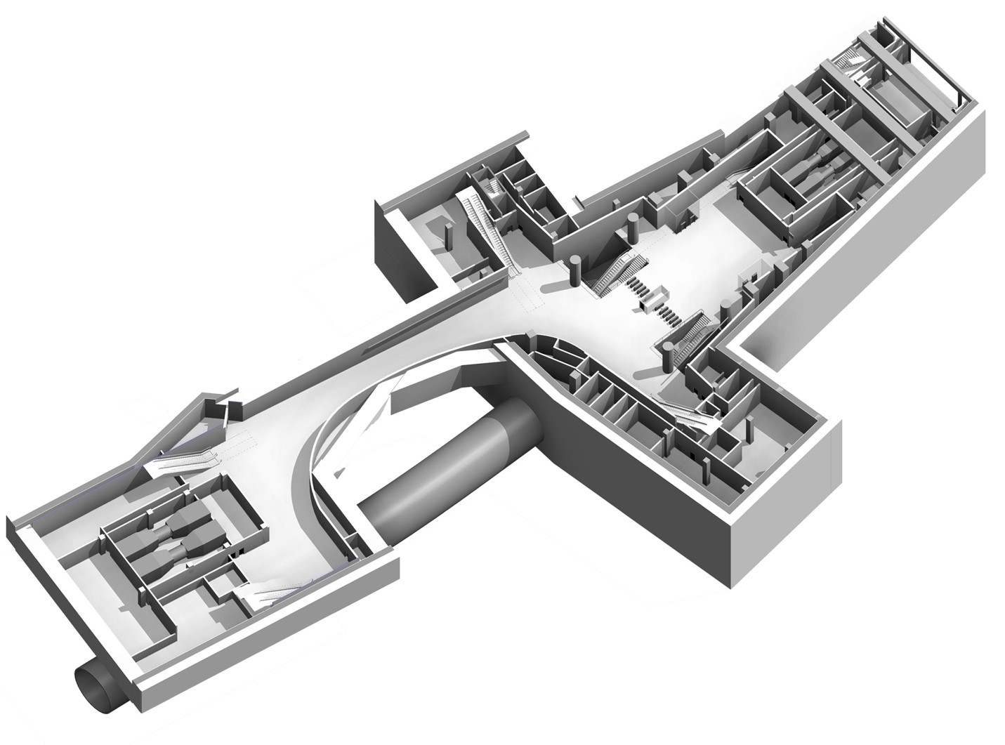
Fig 1. Station 1F2 structural model.
Construction Method: The construction of 1F2 is to be a bottom up construction unlike the Liverpool street station which was a top down construction. The use of a secant pile diaphragm wall with tension anchors into the soil behind the piles will be used to maintain the excavation. The structure will then be built from the bottom in a conventional method.
Soil Conditions: Although not read into the detail the ground conditions on site are set to be quite different to Liverpool Street. The ground is predominately course grain gravels, sands near the surface with more consolidated soils at depth and ultimately layers of rock.
The Engineering Risk.
Ground Water: The main engineering risk identified in this case has been ground water due to confined aquifers and a high water table and high permeability soil. The high permeability of the soil combined with an wxpectation of large fissure will result in a high flow rate of ground water which will fill the excavation and pose arisk to life or at the very least make conditions unworkable.
Settlement: Any attempt to lower the water table will also alter the voids ration and cause settlement of surrounding soil and poses a significant risk of causing damage to surrounding structures.
Solution
Reduce the ground water flow. Ground water flow (Q) occurs when a change in the ground water regime sets up an hydraulic gradient (i), i.e. opening an excavation. The greater the difference in head the greater the hydraulic gradient and the greater the flow, however the length over which the water must flow will also affect the flow of water due to resistance caused by the permeability of the soil. As a result
Ground water flow (Q) =Cross section area (A ) x permiability (k)/flow length (l) x (h1-h2)
Hydraulic Gradient (i) = h1-h2 / l
Therefore there are a number of ways to reduce the ground water flow into the excavation, one using a ground water pumping regime to reduce the difference in hydraulic head or increase the flow path by forcing the water to flow further using a hydrulic cut off.
Ground water pumping reduce head difference: My usual approach would have been to design a dewatering scheme to lower the water table outside of the diaphragm wall to ultimately lower the ground water within the excavation. However due to the risk of settlement and damage to structures within the influence zone this has been deemed unsuitable. Therefore de watering must take place within the excavation.
Ground water cut off increase the flow path. In order to reduce the flow of the water a vertical cut off may be used to reach a lower permeable soil boundary or to increase the length of a vertical cut off to increase the length of the flow path and reduce flow. A typical method for achieving this is the use of piles either sheet or RC concrete. The geotechnical team within Arup have opted to used injection grouting at the base of the pile to create vertical cut of. In this case a TMS (Tube a Machete, read tube with holes in it) is inserted through the pile and grout injected in to the soil to fill the voids. The intention is to us a course grain grout followed by a finer grain grout to create the vertical cut off and reduce the dependency on augured piles.
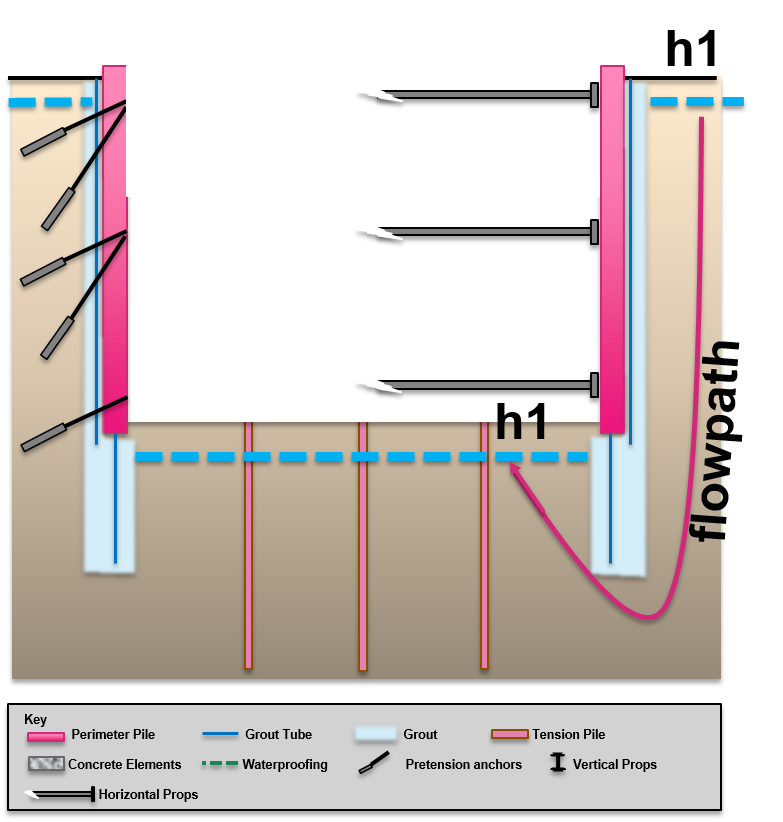
Fig 2. Showing use of grout as a vertical cut off to increase the flow path.
My initial thoughts are that this seems very high tech and potentially engineers trying to be too cleaver. The problem that I raised but apparently has been considered is that the first that anyone will know it has failed is when the excavation starts to fill with water. In this instance it would be too late to increase the length of the secant pile wall to increase the vertical cut off. I stand by to be corrected.
Comments on a post card…..
