Archive
ST Vincents and the DUCTULATOR
After a blogging space I thought I’d let you all know what I’m up to. Shortly before Christmas I finished with John Holland and moved across to the Sydney office of Norman Disney and Young, Norman Disney and Young are a services design consultancy that cover the full spectrum of services consulting (hyd, Fire, Mech, Elec, Comms etc…) and employ 600 employees spread over about 13 offices worldwide. For the time being that includes Ollie in Perth an Me here in Sydney.
My main project at the moment is the Mechanical Services design development of an extension/newbuild and refurbishment of a private hospital in Sydney. The refurbishment includes 5 floor of wards with some 40 beds per floor in an existing 70s built hospital, upgrading the existing to ensure the design is code compliant. The seventies seem to have been a laisse faire time over here with respect to building design and the upgrade includes upgrading of the fire and exhaust systems, as well as upgrade of all he Mech plant. Staged in such a way that the hospital can remain open while the work is done, taking out 2-3 floors only at a time, which poses SIGNIFICANT design constraints. The slab to slab of the existing hospital is 3 metres, with the slab 300mm ‘waffle’ type construction. The ceiling heights are required to be 2.4 meters which gives only 300 mm ceiling void to run all services.
The second part is the construction of a new 14 storey hospital extension. which I am currently developing the Mechanical design for. The building has a number of different uses, all of which help make the design a real headache. The basement is a Laundry, the floor above is a canteen, then office space, operating theatres and the associated sterile spaces, wards, and the top 3 floors are consulting suites for private consulants, all on a floor print of less than 100 square metres.
The design development is due around April which should keep me busy, and NDY is also leading on Electrical and Fire design for the same project, so i’m intending to get some experience in both these areas as well.
Duct Design
For all you E&M 56s out there, I wanted to let you know about the Ductulator! Having struggled to get to grips with the constant friction loss method of duct sizing, I wrote a TMR last year going into detail of Friction loss duct sizing approach verses static regain, so I fully understood the process. It turns out there is an easier way:
Step in the duculator:
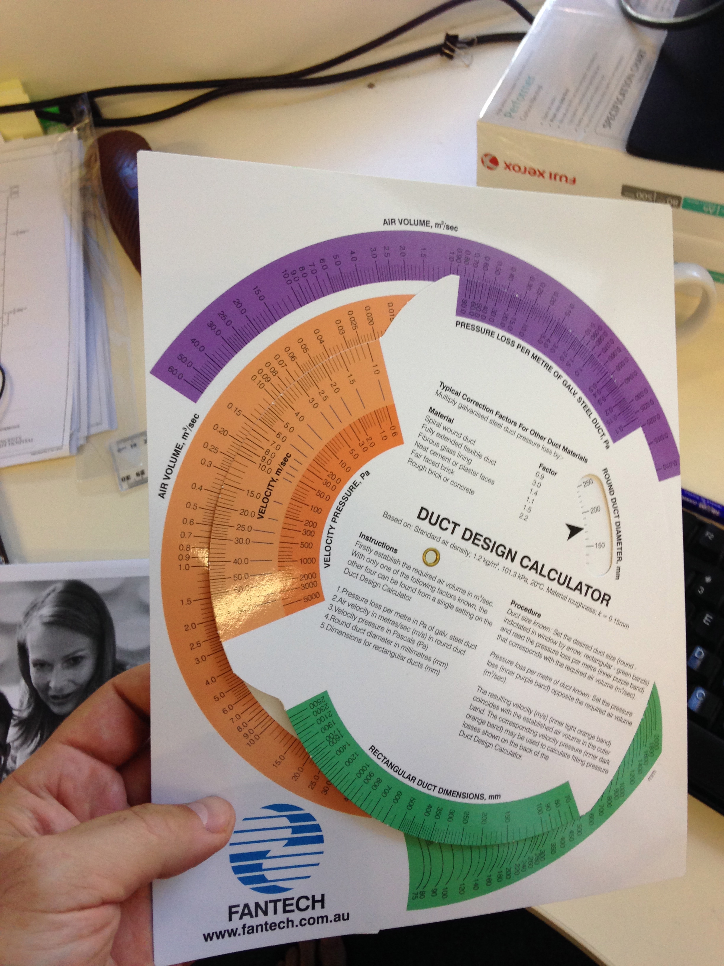
This simple but effective bit of kit is, apparently an essential on any self respecting Mech designers desk. As I’m not a self respecting Mech Designer I stole this one. It uses the friction loss method for duct sizing, to give rough duct sizes. how it works –
1. Rotate the dial to compare velocity verses volume flow rate – The orange part of the dial,or pressure loss per metre against volume (Purple)
2. Read off the associated rectangular duct size (green) or circular duct size (white)
3. Go make a coffee, you’re done.
Design calcs may be required further down the line but for design in principle this works a treat. available from all good TECHnical FAN suppliers.
In other news
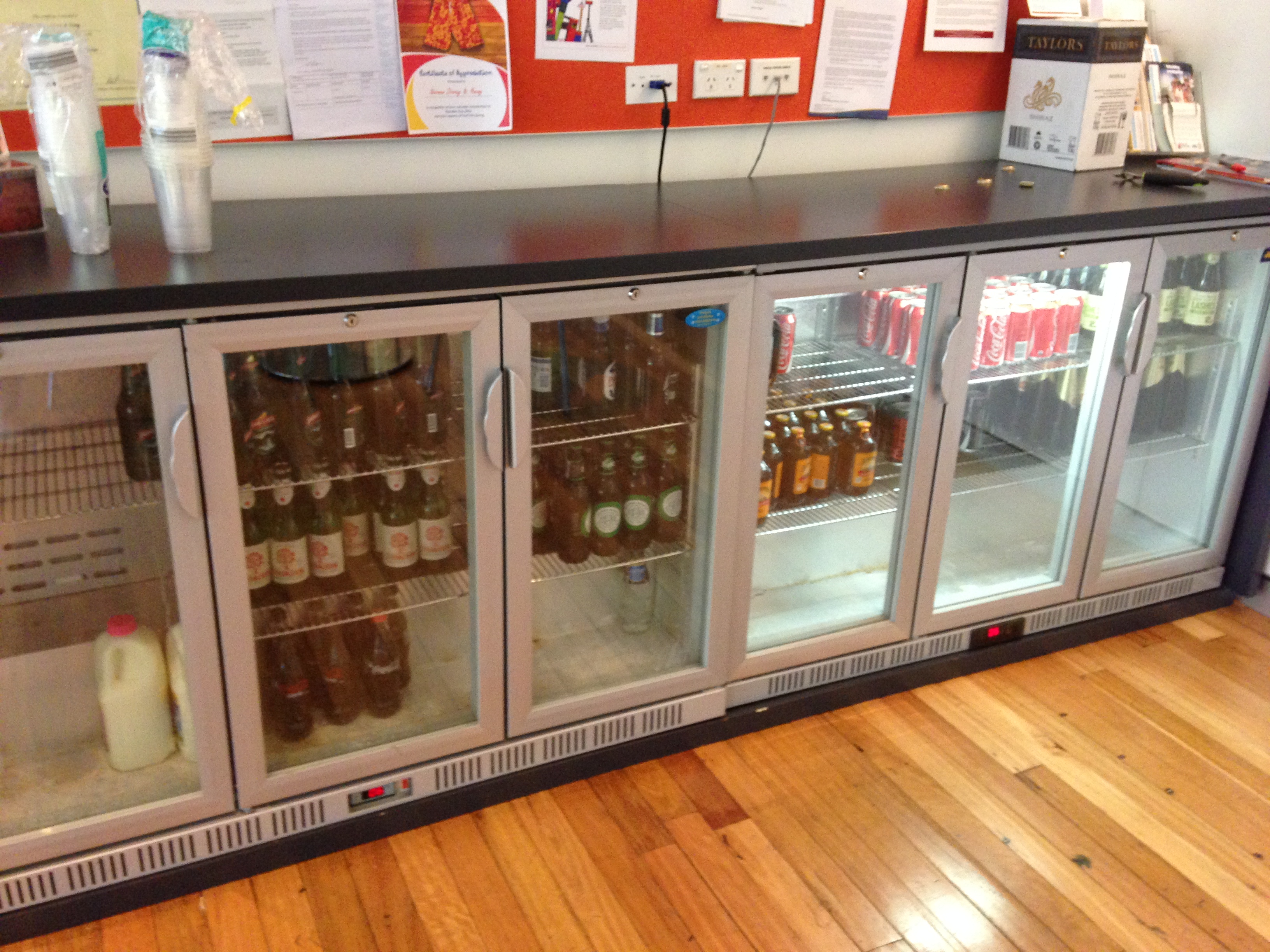
Australia is still awesome. And the consultants here have a friday afternoon beer fridge.
Job cuts in the North Sea
I thought I’d spend a few moments putting pen to paper on the recent announcement by BP to cut 300 out of 3,500 jobs in the North Sea. (This note only refers to BP North Sea Global Operations Organisation.)
This was formally announced last Thursday in a Town Hall, i.e. get yourselves to the Gym for a centralised briefing (except this wasn’t three line whip). Whilst not directly influenced by this announcement I had a certain amount of interest, having been an observer during the recent military job cuts.
The Town Hall was delivered by the Regional President of the North Sea, Trevor Garlick, supported by the VP of HR, David Conway. In contrast to the military redundancy briefings it was not delivered from a script, however, it was clear that the brief had been prepared and was supported by a handful of slides. As can be expected the tone of the brief was also considerably different, in that it was softer and laboured on the fact that the decision to make the cuts was not linked to the cut in the price of oil but is a measure that had been under review and developed since Q4 2014.
So how did BP come to the number 300? The business driver is a simplification and efficiency agenda. In recent years BP has seen a 50% reduction in production, with an increase in costs of 37% and personnel by ~20%, all leading to a level of efficiency that is not competitive in the North Sea. Therefore in an effort to improve efficiency BP has scrutinised the activities in 2014, as it is the engineering, design, fabrication and execution of the activities that is costing the money, not the employee head count. With the activity set reduced the corresponding reduction in associated employee and contractor headcount was calculated. The 300 is split into 200 employees and 100 contractors, though the final numbers and split is still subject to consultation.
The execution of the redundancy programme itself does bare some similarities to the military redundancies. BP is openly inviting those that will take voluntary redundancy to come forward, through a process called expression of interest. It is not guaranteed that an individual will be selected, but it is hoped that it will reduce the number of compulsory redundancies. This process in open for a few more weeks and will close in February. After this point the VPs of each function will conduct a selection process and identify those individual that will be given voluntary redundancy and those that have been selected for compulsory redundancy. It is expected that the selection and announcements will be early in 2015 with those selected for redundancy leaving by end of Q2 2015.
One of the points laboured in the townhall was safety and how that will not be compromised during this process and this has led to certain trades being ‘ring fenced’. In simple terms all offshore worker have been excluded from the redundancy process as a cut in the offshore workforce was considered detrimental to safety. The impact of this is that half of the 3,500 is exempt from redundancy with the remaining pool approximately 1,750 strong. This relates to a 17% cut in the eligible workforce.
How does this affect me in the Project and Modification Team? At the moment I haven’t seen any direct impact in BP, though I expect that in the coming months the team will see some people leave as 80 of the 300 job cuts will occur in the Operations function, in which Projects and Mods sit. Some of this will be through redundancy though I expect some contractors will walk before being pushed as they look for other opportunities before the axe falls. Where these opportunities might be I don’t know, as many of the other operators and service companies are cutting jobs with considerably more gusto.
In terms of activities, I have seen little change in the desire to execute the work that I am responsible for as a significant amount of it is safety related and therefore tied to consent to operate. The remainder of projects have comparatively large operation efficiency impacts and so the business case that supports them remains valid, even with the depressed oil price.
Outwith BP I am starting to see some impact in the delivery of my projects. A number of senior Projects Engineers and discipline engineers in WGPSN have already made the jump and more are preparing to move on. The resultant churn as WGPSN attempts to balance resources will undoubtedly place pressure on the project schedules. In the coming months it will be important to spend more time with the Project Teams, which are unfortunately geographically remote, to keep the delivery on schedule / mitigate any impact that the churn has.
In closing this note I thought I would share Bob Dudley’s (BP CEO) comments at the World Economic Forum in Davos, Switzerland. He said: “We have got to plan on this (the oil price) being down for certainly a year, probably two and maybe three years.” Difficult times ahead for the oil industry and I expect that we will see more in the news.
Concrete Cracking I never knew it was so exciting…..it isn’t!
Background and problem. Within the design specifications for the Riyadh Metro there appears to be on the face of it an oversight in terms of the concrete specifications. The design specifications state that the maximum 2. allowable concrete crack width is 0.15mm. From my now understanding of concrete cracks this is considered to be exceptionally low with the BS and EC specifying a more usual crack width of 0.3mm. The only time that a smaller crack width is usually specified is for water retaining structures. As part of the team and as I showed an incline of interest at one of my first meetings I landed the role of leading small team (myself and on other) in the study of concrete cracking and the means to control it.
The reason behind the particularly strict crack widths is the durability of reinforced concrete within the particularly harsh environment of the Middle East. In the last couple of decades, the region has experienced significant growth in construction with a increased use of reinforced concrete as a construction material. Despite the generally accepted increased durability of concrete over other materials many of the structures are showing signs of deterioration within the 5yrs and the majority will not last the intended design life. A lack of understanding of durability factors in the initial design and construction combined with the use of unsuitable materials, poor workmanship, and lack of knowledge of the environmental affects on the concrete are considered as the underlying factors that lead to the two primary means of concrete deterioration within the Middle Eastare (que dramatic music);
1. Reinforcement Corrosion
2. Sulphate Attack.
In both cases the permeability of the concrete and the exposure of the reinforcement to the harsh environmental conditions is a key factor. Key to the permeability of the concrete is crack width.
Crack widths are a function of the tensile forces within concrete and the inability for concrete to carry tensile stresses (not strictly true, but very low). There are a plethora of mechanism that cause cracks within concrete, however as the designers for the minute we are tackling the one we have most control over first, flexural cracking.
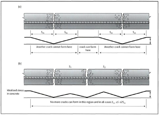
Flexural caking occurs due to loading of the concrete. As a length of reinforced concrete is loaded the tensile stress cause the concrete to strain at the point at which the concrete cannot strain any further a crack forms and the tensile stress is reduced to zero. The tensile stress then builds at a distance from the crack until the concrete can no longer strain and another crack occurs. As the tensile stress continue to build cracks are further opened until the stress is taken up by the steel reinforcement.
The principle factors affecting the number and width of cracks are
1. Cover – the greater the cover the greater the area of concrete that must strain prior to transfer of tensile stress to the steel.
2. Ratio of effective steel. The greater the amount of steel within the effective depth. This can be achieved by using a greater number of smaller bars.
3. Using smaller bars. Smaller bars have smaller diameter so can be placed closer together reducing distance between bars and so reducing concrete outside a zone of influence. Smaller bars also have an overall contact perimeter with the concrete.
4. Use of higher bond bars or reduce the tensile stress within the concrete. Fairly obvious however in our case the materials used are 355n/mm2 steel however the concrete is only C35 and that is considered good in Saudi Arabia.
Solution. The solution has not been entirely obvious or easily negotiated. The obvious answers of adding more steel and reducing the cover are not quite so straight forward. Reducing the cover would expose the concrete and reinforcement to the risk of cracking during curing due to thermal shrinkage as well as plastic settlement and plastic shrinkage cracks (both not discussed here). A reduced cover would also make the concrete vulnerable to chemical attack.
Just adding more steel is also not viable as the greater the amount of steel either the concrete section needs to get larger which will exacerbate the problem or the steel must be stacked in layers. As the steel gets further away from the surface the less affect it will have in the prevention of cracks as the lever arm to the centroid reduces. Greater layers of steel will also reduce the effective depth (distance to centre of steel from centre of compression zone) of the concrete section and eventually the steel will enter the compression zone and no longer be effective in crack prevention.
The solution has been to look at the use of stainless steel as the outer layer of steel and reduce the cover. This will increase the effective depth and reduce the amount of steel required to reduce crack widths. The results of the study I have been leading on are below.
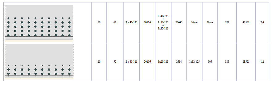
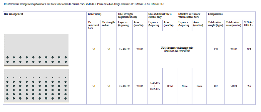
Sections in order 1-4 (top to bottom) all show a section of concrete subjected to a bending moment of 15 MNm a fairly typical load case for the Riyadh |Metro project
- Shows the steel required to carry the tensile loads within the concrete section
- Shows the additional steel required to control cracks to less than 0.15mm with a cover of 50mm. Note that the addition of further steel having a decrease in effect in reducing the crack widths, with further layers of steel only reducing crack widths by a smaller and smaller fraction of a mm.
- The addition of smaller bars in between the larger bars but maintaining the cover reduced the steel requirement as the effective depth was increased. Cover was maintained at 50mm and cracks widths were limited to less than 0.15mm
- The addition of stainless steel within the original 50mm cover reduced cover to 25 mm but further increased the effective depth and allowed the removal of further crack control steel from within the concrete section.
Conclusion
Conclusion to the study was that while stainless steel may be more expensive the use of stainless steel would remain cheaper then the use of additional steel to control crack widths.
In other news the office had a jazzy shirt to work day to raise money for charity. After a rather uncomfortable journey on the underground I arrived to work to find that I was one of only a handful of people to have participated and ended up looking more of idiot in a client meeting then I normally do.

Yep the design office really is that exciting.
The Queen is not the best landlord
I’m working with a small firm of consulting structural and geotechnical engineers called Michael Barclay Partnership (MBP) Limited Liability Partnership (LLP). They employ roughly thirty engineers, ten CAD operators and some admin staff. We’re based on the Strand, just down from the Savoy Hotel and the building is owned by the Queens personal estate. Sounds great right? Well our office is on the top floor of the building and we’ve had no heating since Christmas!

The firm’s business model is to achieve a high turnover of work on small to medium sized projects in London and the South East of England. Their work is predominantly in domestic/residential structural design of new build (or redevelopment) projects, but they also have public, retail and commercial projects on their books.
The role I have taken up is as a Junior Structural Engineer. I’ve been given responsibility for the design of a residential development in Battersea, which I have been working on full time. The developers budget for the project is approximately £5m. The design fee will be no more than 1.5% of this. In addition to this design work, I have been on a number of site visits around London (or simply the Royal Borough of Kensington & Chelsea) to gain practical experience of basement construction, underpinning and significant structural alteration works.
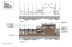
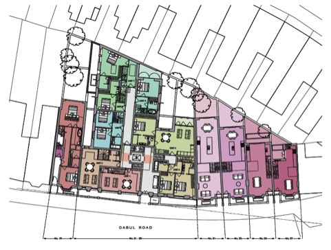
The project in Battersea I am responsible for is the redevelopment of a Baptist Congregational Hall built in 1895. The developer hopes to convert the Hall into thirteen flats. Adjacent to the Hall are five terraced properties. It is hoped to demolish four of these and replace each of them with new 2×2 bed houses (these are the four properties to the east on the below plan).
I completed a Desk Study and Construction Method Statement for the planning application, which was submitted just prior to Christmas. Since then I have worked on the Concept Design of the development. Once my line manager, one of the four principals of the LLP, approved this I moved onto the Developed Design. I am now in the throws of modelling the structure such that I can verify my concept design. After this I will finalise the Detailed/Technical Design.

The last five weeks of design office time have gone exceptionally quickly. I feel as though my learner plates are coming off at last. A little like Joe’s office, most people design using British Standards. I’ve opted for EuroCodes and this doesn’t seem to be a problem. The last week, or so, I’ve immersed myself in learning how to model structures using Robot, which is part of the AutoDesk family. Here his a screen grab from one of my models.

It is a pretty powerful tool and I’m now just about getting to grips with it. We also use Tedds which is great for very speedy verification of simple elements, and 2D analysis. Some of the structural challenges ahead of me include retaining the front and side facades of the Congregation Hall, underpinning the retained facades and party walls to dig the basement, erecting new roofs, designing a new core within the building and installing a new steel frame within.
Monitoring the planning application online for the Battersea development a lot of local residents have objected to the fact there is no off-street parking. The developer did commission a parking study but this was done on a Wednesday afternoon in mid December and showed there were plenty of free parking places! The residents are up in arms with this since it is not representative of their parking ‘crisis’. Therefore I won’t hold my breath that planning with get the green light immediately.
All in all it should be a good five months ahead. There is plenty of interesting work coming into the office which I will no doubt be involved with.
My eyes hurt.
Well life is slowly but surely becoming relatively normal again after the worst Xmas ever. The combination of a foot operation the week before Xmas, my garage (which was my AT store) being burgled the day before the foot op and no skiing was pretty depressing. Thankfully the New Year has started more positively and I have settled into the design office at Ramboll in the New Forest quite nicely.
Just as Rich Phillips had warned me, it is a bit quiet but everyone is very nice and extremely helpful. The pace of life is much more sedate and for once I am not the biggest geek in the room! Luckily I sit near a guy who is also a very keen mountain biker and behind a girl who has just finished her geology degree and is keen to explain principles to me. Rich has paved the way in what they expect and what sort of things we need to cover so thanks Rich if you ever read this!
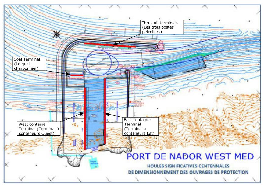
My first task has been of mammoth proportions. Ramboll have been tasked to come up with a design for a breakwater for a port out in Morocco. Initially I thought great, you just design the core, protective rubble layer, do a bit of maths for settlement, wave and boat impact loads and off you go-WRONG! This breakwater is 3km long in 35m of water and a purely rubble breakwater would have needed to be 450m wide! To add to the problems it would be founded on around 8-10m of soft silt which has the compressibility and strength of a soggy bathroom sponge. Ramboll changed the design to be a rubble mound with a concrete caisson (30m wide and 35m tall) to bring the structure above sea level.
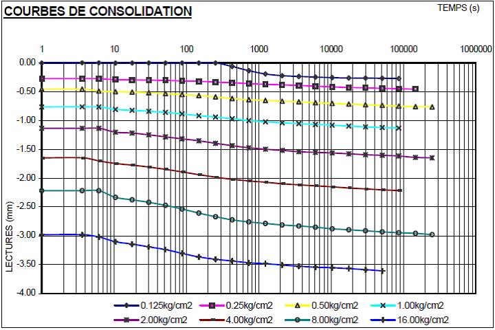
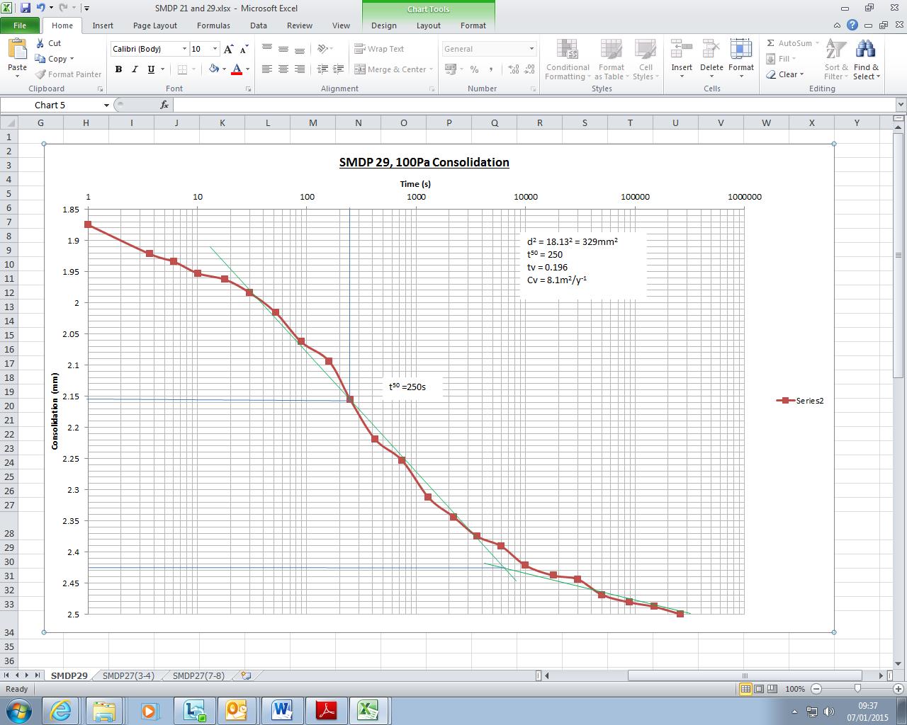
My initial task was to go through the 1D oedometer tests (which were all in French) and re-plot them on bigger axes to be able to establish the primary and secondary compression lines of best fit. This meant getting my head back into the books to understand the oedometer test and the theory of consolidation. I then had to calculation the coefficient of consolidation (cv) using the Casagrande logarithm of time fitting method. This involved plotting lots of points, fitting lines, measuring time values and calculating cv on a spreadsheet. The work was quite time consuming and monotonous and it hurt my eyes but it was a good opportunity to fully understand some theory.
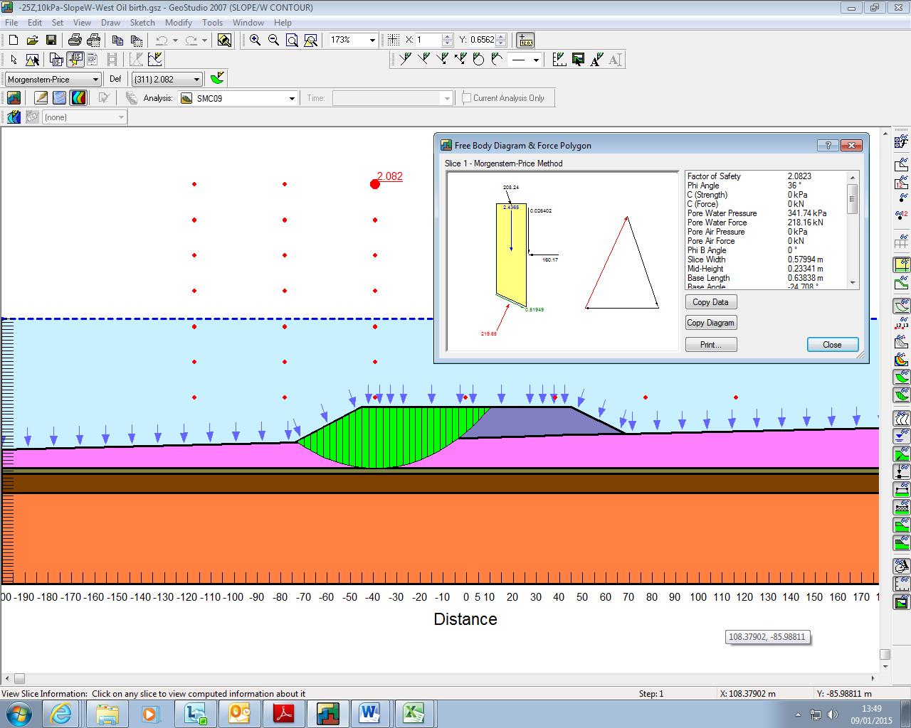
My second task on the project was to model part of the breakwater using the slope stability software SLOPE/W. Firstly I had to input the geometry of the problem and assign the initial material parameters which was the easy part! The software then calculates potential slip surfaces using stability of slices within a slip circle. The output is a factor of safety which must be above 1.15 in the temporary condition. I had to break the model down into stages starting with just the breakwater structure, then the concrete caisson followed by layers of fill in the caisson. Again this initially sounded simple until I had to incorporate the increase in strength of the silt due to consolidation. I had sudden flashbacks of John’s lecturers hammering against the board trying to get us to explain the difference of drained and undrained parameters. Well John, having read a few chapters in Craig’s Soil Mechanics book I think I get it!
The theory. When a fine grained material is loaded it is compressed and initially the load is taken by the pore water resulting in an increase in pore water pressure. The initial (undrained) strength is quite poor which is why fine grained materials often fail suddenly on loading (John’s grain silos). The excess pore water pressure dissipates at a rate depending on the permeability which results in the primary compression part of your 1D oedometer test curve. We also added vertical sand drains which shorten the drainage path and speeds up the rate of consolidation. As the excess pressure dissipates the load is transferred to the soil skeleton increasing the strength (drained conditions). Is that right John???
My task was to calculate the increase in strength after each month and adjust my model parameters accordingly. This became increasingly complex as different parts of the silt under the breakwater had different loading for varying durations. I finally managed to create a crazy spreadsheet and I got my model to take a caisson that was half full over around 4 months when disaster struck. The next 5m of fill caused a collapse even if the silt was left to consolidate 100% after the previous loadings. So it won’t work, back to the drawing board! One of the other guys has also been modelling the seismic effects and the structure also fails in sliding so we are now considering steel piles, it’s going to be one expensive project!
I have also been working on a project closer to home near Bermondsey station with part of the London Bridge upgrade. I had to understand the Bermondsey Dive Under Box concept of construction and write a specification for new trial holes as some of the low headroom bored piling did not work with the ground conditions. I suddenly realised that it’s quite difficult to dictate where the holes need to go having never been on site and only seen drawings of the proposed structure. I now feel really sorry for the design engineer from Buro Happold who I got really annoyed with at Battersea for wanting to put boreholes in really inconvenient places!
In summary I think this will be a good placement with plenty of support for CPR and a nice working environment. I actually get the time to sit and understand the principles before I start number crunching. The commute is okay at the moment and it is nice not to have to drive back somewhere on a Sunday evening, let’s hope I don’t end up posted to Kinloss next!
Legal problems…
Having left behind the big smoke in favour of a more sedate life back in Devon, I’ve joined Atkins consultancy, and am based in Exeter. Part of a global brand, the Exeter office takes the lead on local projects which offer a wide variety in scope, and has offered me to the chance to get stuck in from the off. So far, I have been involved in four main projects, each at different stages of the design process.
They are as follows:
1.Slope stability analysis on an earthfill reservoir embankment in Bruton, Somerset.
2.Production of a scoping request ahead of a planning application on Linhay Hill Quarry, extension works, Ashburton
3.Project management of a planning application for an organic foodwaste recycling plant, Avonmouth, Bristol
4.Drainage design on new school within a development scheme at Mudford, Somerset. Whilst you’re still reeling from the sheer scale and profile of these projects (Burj Khalifa 2 is next month apparently…), I will give you a snapshot of some of the planning legislation and guidance that I have become familiar with on the Avonmouth job.
Background. Wessex Water Enterprises’ business unit, GENeco, leveraged spare capacity at the Avonmouth sewage treatment works to build an organic food waste plant in 2010/11. This ‘stomach in a shed’ takes approximately 30,000 tonnes of food waste from across the wider Bristol region, and processes it into methane and digestate fertiliser. These by products are recycled in to a number of uses including fertiliser for the agricultural industry, and even to power the cities buses. Check out the link to a CBBC rundown on the plant, which is at about the correct level for my childish mind…
http://www.geneco.uk.com/Food-waste-recycling/Default.aspx
Given the success of Phase 1 of this development, GENeco wishes to submit a new planning application to deliver Phase 2 of the works. The Avonmouth development will constitute an expansion of existing works delivered in Phase 1. The proposed new development will add an additional 30,000 tonnes per year of capacity to the plant. GENeco have approached Atkins to support a planning application for an expansion of the plant.
Client Specification. Wessex Water support their own small engineering services team, and have decided to deliver some of the aspects of the planning application themselves. Whilst this has led to a slightly incoherent approach, much of the planning application from Phase 1 is likely to remain extant which should serve to de-risk this process. The scope of Atkins involvement has been reduced to the following sections of the report.
(1). Scheme Drawings
(2). Transport Statement, to include travel plan
(3). Landscape and Visual Impact Assessment
(4). Site specific flood risk assessment
(5). Odour assessment
(6). Air quality assessment
Contract. Atkins have utilised a standard form of consultancy agreement; specifically the Consultancy Services Contract. This enables the provision of consultancy services and deliverables, in which the deliverables are clearly defined. Each deliverable is priced in isolation; a clear explanation of the basis of the costings is given, including named participants and their hourly rate. Either party may request a change to the scope or execution of the services, but importantly the consultant has no obligation to perform the variation until all variations in fees and services have been agreed. In this instance, when the scope is unclear, this provides a risk share for both parties, as each development in scope can be judged on its individual merits and agreed upon in isolation. However, the key managerial issues in this example are at the local level. The scope straddles a number of functional areas within the broader Atkins organisation, and so implied in the deliverables is a project management function. However, in order to remain competitive at tender, project management fees were ‘scoped out’ and currently those costs are lost in each of the departmental fee proposals.
My role. Perhaps predictably, I have taken on the role of ‘free at point of sale’ project manager. Initially I prepared and issued Inter Unit Work Orders (a formal arrangement between departments that agrees requirement, program and costs) to each department and negotiated their program lengths and costs. This was captured in an offer letter, which was sent to the client for agreement. The tender was then awarded. I have issued a tasking order which provides an overview and initial proposal layout, with guidance on program and resourcing. I included an RFI matrix, which has enabled me to liaise with the client and key stakeholders, such as Bristol City Council, to manage the information flow between all parties. Weirdly, this has made me the toast of the town! I have also been tasked with the production of the Flood Risk Assessment, which I submitted this week aswell as Odour and Noise Assessment.
Legislation All the planning policy guidance is contained within the National Planning Policy Framework (2012). Aswell as being a ripping good yarn, it sets out all the governments planning policy in one easy to read document. This is considered a huge improvement to the system before 2012. In the context of flooding, the broad aim of the National Planning Policy Framework, March 2012, is to reduce the number of people and properties within the natural and built environment at risk of flooding. To achieve this aim, planning authorities are required to ensure that flood risk is properly assessed during the initial planning stages of any development. The responsibility for flood risk assessment lies with the developer and they must demonstrate the following:
- whether the proposed development is likely to be affected by flooding;
- whether the proposed development will increase flood risk to adjacent properties; and
- that the measures proposed to deal with any flood risk are sustainable.
Sequential Test and Vulnerability Classification. In order to establish these aims, the ‘Sequential Test’ is used to steer new development to areas at the lowest probability of flooding, with the starting point for the sequential approach being the flood zones detailed in the Technical Guidance to the National Planning Policy Framework. Development should be directed to Flood Zone 1 wherever possible, and then sequentially to Flood Zones 2 and 3, and to the areas of least flood risk within Flood Zones 2 and 3. Where there are no reasonably available sites in Flood Zone 1, local planning authorities determining planning applications for development have to take into account the flood risk vulnerability of land uses, again outlined in the Technical Guidance to the National Planning Policy Framework, Vulnerability Classification.
Risk Categorisation. Flood risk includes the statistical probability of an event occurring and the scale of the potential consequences, and the risk is estimated from historical data and expressed in terms of the expected frequency (or ‘return period’) of a flood of a given magnitude. For example the 10-year, 50-year and the 100-year floods have a 10%, 2% and 1% chance respectively of occurring in any one year, and those values are termed the Annual Exceedance Probability, AEP. However over a longer period the probability of flooding is considerably greater, hence for example, for the 100-year return period:
- There is a 1% chance of a 100-year event occurring or being exceeded in any year.
- A 26% chance of it occurring or being exceeded in a 30-year period.
- A 51% chance of it occurring or being exceeded in a 70-year period
The Technical Guidance to the National Planning Policy Framework, March 2012 defines flood zones in relation to the probability of river and sea flooding, ignoring the presence of defences, and details the appropriate land uses, Flood Risk Assessment (FRA) requirements and policy aims for each zone. The Environment Agency provides Flood Zone maps available via its website which are used as the starting point for all FRAs. From inspection of those maps, the central section of the Avonmouth site, i.e. the existing reception centre near the drainage ditch (the ‘rhine’ network) lies within the Environment Agency’s indicative flood zone 3, defined as high probability of flooding, by the Agency. The Technical Guidance to the National Planning Policy Framework, March 2012, also requires the vulnerability of the development or land use to be taken into account as the consequences of flooding may not be acceptable for particular types of development, and it defines Flood Risk Vulnerability Classification for the proposed use of development sites. With reference to that table, the proposed development land use, namely waste treatment facility, is classified as ‘less vulnerable’.
Town and Country Planning (Flooding) (England) Direction (2007) Due to some inappropriate developments being granted in flood risk areas against advice of the Environment Agency, the Secretary of State under the County Planning (General Development Procedure) Order 1995 (“the Order”) made the Town and Country Planning (Flooding) (England) Direction 2007 (the Direction) which came into force on 1st January 2007, to provide a safeguard against such cases The National Planning Policy Frameworks states the requirement for a Regional Flood Risk Appraisal to provide a broad overview of the flood risk issues across the region; in this instance the South West of England. It seeks to highlight key areas where more detailed study is required at a sub- regional level. I consulted the South West Regional Flood Risk Appraisal (RFRA), February 2007 with regard to the proposed development, and Avonmouth is considered as an area of sub regional flood risk. The area of Avonmouth, Severnside and Royal Portbury Docks are characterised by a ‘substantial coastal flood risk’, where property is at risk from tidal and fluvial flooding. Additionally, surface water drainage can be subject to ‘tidal locking’ at high tide. This risk is mitigated by tidal flood defences which are installed between Avonmouth and the Severn Beach. These offer protection up to a 1 in 100 year event. That said, the effect of climate change and the rise in sea levels is a major concern in the Avonmouth region. It is estimated that severe tidal flooding events will be six times more likely to occur by 2060 (i.e a 1 in 200 event now, will become a 1 in 33 year event).
Planning Policy Statement 25 (PPS25) Development and Flood Risk (Communities and Local Government) issues detailed guidance on the assessment and management of flood risk. Within this it directs local authorities to produce a Strategic Flood Risk Assessment for their area of administration. A Level 1 initial assessment is carried out for all the administrative area by the Local Authority to understand the flood hazard. Where this study indicates an area of flood risk, a second, and more detailed study is commissioned to collect further information of the distribution of the flood hazard. The Level 1 SFRA in this case, indicated Avonmouth as a key area requiring further detailed assessment of fluvial and tidal flood risk. The Level 2 SFRA states that the vast majority of the Avonmouth area is considered as at a high probability of flooding (Flood Zone 3a – 1% AEP river flooding or 0.5% coastal flooding). If there were no tidal defences, extensive flooding could be expected. It is also clear that the Avonmouth/Severnside area is very susceptible to tidal/surge flooding from overtopping the defences. In this instance, the sequential test demonstrates that there are no alternate reasonably available sites in areas with lower probability flooding. As stated, the development is proposed as an extension to the existing anaerobic digestion plant, and therefore needs to be located adjacent to the existing works. As the Bristol STW is located entirely in the designated flood zone 3a, there are no alternate lower probability (zones 1 and 2) which would be preferential for the proposals. The ‘Exception Test’ should therefore be applied. In this test, it can be shown that:
- The development provides wider sustainability benefits to the community that outweigh flood risk
- It is proposed on land previously developed.
- A site specific flood risk assessment will be included to demonstrate that the development will be safe, without increasing flood risk elsewhere
Next steps… My flood risk assessment demonstrated a medium to high risk from a tidal event, which is increasing with climate change. Fluvial flood risk is medium. The Avonmouth flood defences in the immediate area mitigate this risk somewhat, but The Environment Agency don’t own the full length, and therefore the maintenance scheme is hit and miss at best. I therefore recommended that the residual risk remains at medium to high. I approached the client informally ahead of the publication of the risk assessment to recommend further consideration to mitigation measures. I was told in no uncertain terms that there was no aspiration for this, and certainly no budget at this stage, and given the ‘less vulnerable’ status of the industrial unit didn’t justify further expenditure. Ill still be taking my wellies on my site visit on Wednesday….
Chilled Water System Heat Exchanger
2015 has got off to a fairly slow start for the Building Services team at Jacobs in Brisbane. There is a lot of work in the pipe line that we are expecting to land at any moment, but for the time being I am keeping busy with some relatively small research tasks, blogging and the mountain of reports that need to be submitted in January!
This task is to source a heat exchanger to interface between two separate chilled water loops, each serving a different hospital.
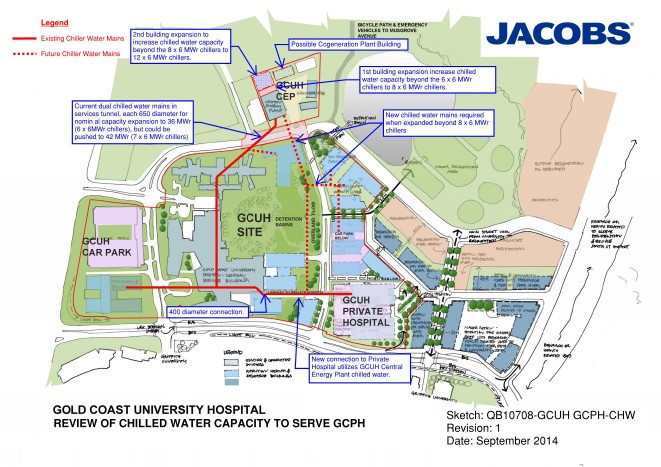
Construction of the Gold Coast University Hospital (GCUH) for which Jacobs won the contract for the building services design, was completed in 2014. The client, Queensland Health, entered into a contract with a private health service provider to supply various utilities / services to the new Gold Coast Private Hospital (GCPH) which is to be built on an adjacent site. The services / utilities include standby power, fire mains water supply, HV system reticulation, potable and reclaimed water supply and chilled water for the air conditioning system.
The design and documentation for the GCUH chilled water system was written based on an assumption that the GCPH chilled water ring main would be directly connected. However consideration is now being given to the possibility of maintaining segregation between the two systems by having two separate ring mains and a heat exchanger as the interface between the two.
The maximum working load of the existing GCUH is 22.8MWr (based upon assessment of current use and estimated increases when the hospital is at full working capacity) and the maximum working load of the GCPH is assessed to be 3.8MWr. With a required redundancy capacity of n+1 (one spare chiller to allow maintenance as required) and a combined maximum load of 26.6MWr, the requirement is for 6 x 6MWr chillers. This is an increase of 1 from the existing chiller set and these additional works have already been allowed for within the existing plant room.
With the maximum capacities in mind, the specified parameters within which I have been told the heat exchanger must work are as follows:
- 3.8MWr max cooling
- Split of 6^C, entering the heat exchanger on the GCUH side at 6^C and leaving at 12^C
- Approach of either 1/2^C or 1^C, the temperature difference between the outlet temp of the GCPH side vs the inlet temperature of the GCUH side.
So before I contacted suppliers, i calculated the volume flow rate of the loops as follows:
Q = M C ^T
3.8MW = M x 4186j/Kg x 6^C
M = 151 l/s
Other considerations are the pressure drop across the heat exchanger, which will dictate the pumps required, and the pressure of water the heat exchanger must be able to cope with. I have been advised that the pressure drop would be in the region of 50KPa at best and should probably not go much beyond 100KPa. I have assumed the pressure to be in the region of 10Bar as I have no further information at present.
I contacted two suppliers, Alfa Laval and Swep, who provided options as follows:
| Ser | Description | Capacity | Approach | Split | Volume Flow Rate | Pressure Drop | Unit Cost | Quantity | Total Cost |
| MW | °C | °C | l/s | kPa | AUD | AUD | |||
| 1 | SWEP B649 | 4 | 1 | 6 | 160 | 100 | 13265 | 4 | 53060 |
| 2 | SWEP B649 | 4 | 1 | 6 | 160 | 50 | 14720 | 4 | 58880 |
| 3 | SWEP B649 | 4 | 0.5 | 6 | 160 | 13720 | 16 | 219520 | |
| 4 | Alfa Laval HEX | 4 | 1 | 6 | 160 | 100 | 108919 | 1 | 108919 |
| 5 | Alfa Laval HEX | 4 | 1 | 6 | 160 | 100 | 130698 | 1 | 130698 |
| 6 | Alfa Laval HEX | 4 | 0.5 | 6 | 160 | 224427 | 1 | 224427 |
Conclusion
Whilst the use of a heat exchanger simplifies maintenance ownership issues between the two hospitals, and the separate chilled water loops provide an element of isolation should there be any problems on the GCPH loop, that comes at significant cost.
The system would require additional pumps, again with an n+1 redundancy, to pump the water through the GCUH side of the heat exchanger, whereas if the chilled water is connected directly there is only one pump set required to service the branch.

The capital cost of the heat exchanger itself can be seen in the table above and is significant, added to that is the requirement for additional pumps to serve the GCPH side of the exchanger as shown in the diagram below. These pumps also have significant capital cost and there are also the associated maintenance costs to consider. There is also the added issue of having to house the heat exchanger and pumps somewhere within the GCPH.
Based upon these factors, I cannot see how the use of a heat exchanger could be considered a viable option, but at this stage I have just been tasked to source options. I will discuss with the PM as to the way forward.
USACE Design Phase – Initial experience
Though staying within the same overall organisation (USACE), my office has now moved 80 miles south. Instead of an hour car ride, it is now a 45-minute train trip direct to the front door of the 10-storey downtown office block, experiencing all the ”sights and sounds” of Baltimore en-route!!
I was initially placed in ”Civil Works” – involved with levee design, stream and coast rejuvenation, waterways, Hurricane Sandy relief ops etc. Some really interesting stuff, but projects were very long-term and I would see little opportunity for tangible design. There were several reasons for that being my initial placement, largely I think as a hangover from Matt Fry’s good works he did whilst he was there, but project opportunities have now changed. So with a few chats and explanation of my DOs I managed to take a swift turn to the right and move to the Military Design Branch.
The Design Branch is 70-strong, with several sections: architecture, structural, geotech, site development, elec and mech engineers with many sub-specialities within each section. The number of projects that the Branch oversees (design, specification write-up and/or review) is immense. At the height of the US Army Base Realignment and Closure programme from 2005, the Branch was only designing 3% of its projects…but the total amount of projects being managed was over US$2billion! Now, on average, the Branch designs about 13% of its projects – the remainder are contracted out and then reviewed by the Branch. $50 Million is about the present capacity for an in-house design.
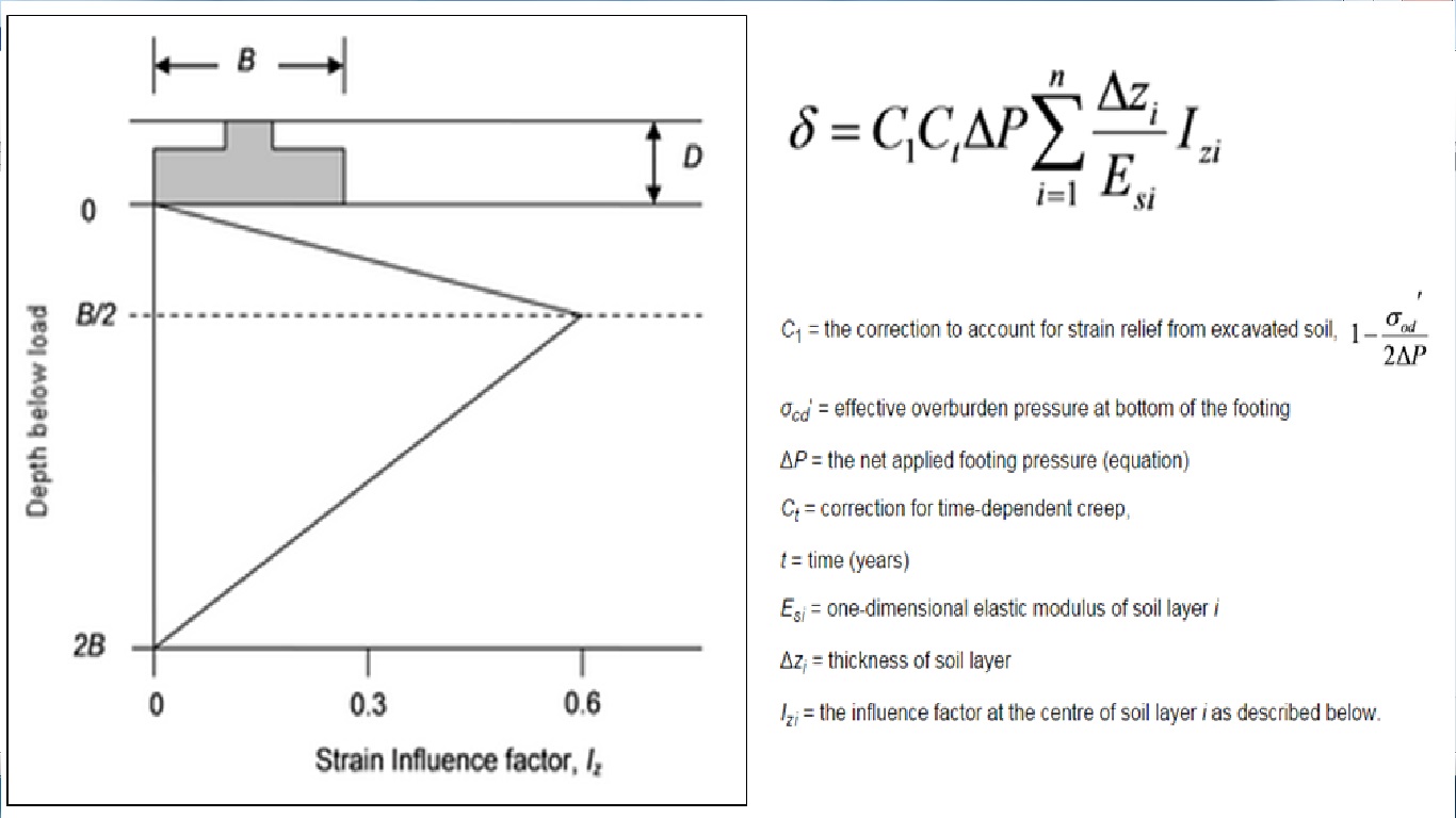
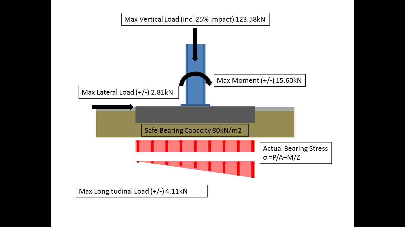
Now targeting my weaknesses – E&M, and Soils…I have already waded into a pump/lift station design, as well as preliminary shallow foundation footing sizing for a US Government testing facility in order to feed into the structural section for further detailed design in due course. The design experience gained in Phase 1 is starting to come to the fore – it took a little while to shake off the cobwebs, but it soon came flooding back (alongside much JM-note referral!). Being able to hold your own with certain specialists, gains credibility and responsibility quickly (that’s what I naively think so far!). To date, the shallow foundation design has been most challenging, particularly due to unit conversion (structural loading in ‘kips’ to name but one!…so I quickly turn everything back into the bosom of ‘kN/m2’), and then running through text books and new ACI codes. ULS design reverts to Terzagi for bearing capacity checks, taking q(ult) and dividing it by a FOS of 3 to get ‘net’ ultimate bearing capacity. For SLS checks, I have been directed to use the Schmertman Method – for those interested, it calculates settlement from layer stiffness data, bearing resistance as well as a time factor for creep (although the latter has had little influence). The method proposes a simplified triangular strain distribution and calculates settlement accordingly; once mastered with an excel spreadsheet, it has been quite a user friendly method to quickly manoeuvre parameters within.
Having attended several design meetings on other projects two things have already become quite apparent:
BIM. Or, the lack of it! There are essentially three different design systems worked on by a design team – Civil 3D by site development (outside the 5-ft line), Revit by mechanical engrs and MicroStation by electrical engineers. Though great for their various disciplines, USACE is admittedly way behind private industry when it comes to BIM. A huge amount of time is wasted with different disciplines coming together to overlay their programmes in order to deconflict and then redesign accordingly. Federal systems move slowly in every way – recruitment, IT uptake, project funding etc etc (I will be going on design charette next month for an armoury project, designated for congressional funding in 2022!!!).
Generalist vs Specialist. In-house design dramatically stretches the Branch – designs are chosen for this exact reason…to maintain design credibility. The Branch would quickly become generalists if all they did was design reviews. Conversely, as a ‘military’ generalist I have been able to save a lot of time for the 100% ‘civilian’ design Branch answering questions on Force Protection and general physical security that have heavily influenced military site design. They could do with a FPE ‘specialist’!
In short, I foresee this being a great experience with some interesting opportunities to hopefully continue getting stuck into and to keep topping up the DO’s!
Phase 2? Done. Hello phase 3.
Well I thought I’d kick off the New Year with a blog and step off with the right intentions.
I’ve been in the design office a couple of weeks now and it’s been fairly gruelling to say the least. Reading back through some of the blogs from this time last year it appears that the majority of the PET(C) 60 course experienced the same mixed feelings at the start of phase 3, with some hilarious inputs from Rich Phillips.
So I have started work with a small consultancy located in Scunthope, NE Lincolnshire and have quickly established that I am not cut out for the daily commuter grind and office environment.
The consultancy, CR Parrott Consultants Ltd was set up in 1994 by Chris Parrott (MD) as a structural engineering consultancy as he is a chartered structural engineer. Over the course of the last few years the company has steadily expanded and now employs approximately 30 staff across 2 offices. The company now offers a professional engineering consultancy, project management, technical support, architectural and 3D visualisation services. This is quite a broad spectrum of activities for a small workforce but reflects the nature of the work in the area as Lincolnshire is not renowned for its cutting edge civil engineering.
I have been placed in the structural engineering design team, headed up by the senior chartered (IStrucE) structural engineer with 3 further assistant structural engineers from various backgrounds. The size and nature of the company means that I am likely to get a good spectrum of exposure to the different consultancy disciplines with a real chance of being able to construct something I have designed during the 7 month period.
I spent much of my early time in a similar vein to the early days of phase 2, looking through job files and drawings, attending a number of briefs and re-sharpening my academic pencil. The Senior Structural Engineer set me a number of revision topics and seminars to work through for my first few days and over Christmas leave (!) predominately focussing on frame analysis and steel and timber design. All good stuff for the CPD log.
Last week I was given my first real design responsibility and it came in the form of a foundation design for an overhead span crane to be constructed inside a steel portal frame hangar. The initial job entailed a detailed survey and structural report on the existing crane runway beam positioned inside the building to ascertain whether it had sufficient strength to accommodate a larger crane (from 2.5T to 10T). It did not. This work was completed by the Senior Structural Engineer and the analysis revealed that the existing foundations and crane runway beams would be overstressed and incapable of taking the additional loads. A number of recommendations were made including a C-Section steel top hat surge girder on top of the existing beam (to improve the stiffness in the yy axis) or the use of RSA or CHS between the portal columns to reduce the effective buckling length of the beams. Both of these options were discounted due to the amount of additional work required to facilitate the construction due to the access limitations. This was sent to the client who subsequently came back to request a bespoke crane that will sit inside the building footprint. Whilst the consultancy would normally design the steel frame for the crane, this has been subcontracted out to the crane company who have an ‘off the shelf’ solution. This makes our life easier as we get the frame dimensions with the static and dynamic loads clearly set out, reducing our analysis time.

Existing crane runway beam.
Foundation Model.
So the first job was to assess the buildings footprint and establish where the crane would fit in the area specified by the client. This raised a number of issues including the clearance of the new crane under the existing and the proximity to the ground beams running underneath the portal frame columns. The building plans were located and the existing slab (180mm) was analysed and it was established that drilled and grouted bolts in this slab would not be sufficiently strong to accommodate the frame. So the plan is to locate an area where the frame will fit (in-between a number of drainage channels, not inside the ground beam footprint), break out the existing floor slab and construct some bespoke foundation pads for the frame columns, tied into the existing ground slab. Simple enough and a perfect warmer for yours truly. I have now completed the preliminary calculations for a RC foundation and await the familiar red pen of the Senior Structural Engineer prior to inputting the data into Masterseries for final analysis. I have also started the AutoCAD drawings that will form part of the portfolio of work that the client will receive. The following are a couple of reflections on my time and work to date that also form part of AER 4.
Reflections:
Design. It has become quickly apparent that it is much tougher to design structural elements within existing infrastructure than on a clear site or on in an academic environment. Whilst an obvious statement the challenge lies in understanding the design fundamentals enough to manipulate them as necessary to accommodate a functional yet cost effective and economic design. This is something I feel I am already learning and will come with practice and experience.
Seminars. During the first weeks of phase 3 I was given a number of design tutorials to work through, predominately in timber and steel design, to catch up with the other Assistant Engineers who had already taken the sessions. The seminars are led by the Senior Structural Engineer and occur on a weekly basis for a couple of hours in addition to a number of Masterseries training sessions that occur less frequently. These sessions have proved invaluable, not only as a good revision period but as useful hours towards my Continual Professional Development (CPD) Record. It is also a worthwhile personal lesson to see even relatively seasoned design engineers refreshing the fundamentals of design and highlights the importance of combating skill fade. This will inevitably be all the more important as a Professional Military Engineer and highlights the importance of maintaining a thorough CPD.
Software. The structural software utilised by CRP is the Masterseries design suite and whilst more complex than StaadPro, with a greater level of modelling detail that can be incorporated, the fundamentals are similar. The availability of the software across the team is limited and whilst the software is loaded onto each computer in the office a pen drive ‘key’ is required to open the software. This is controlled by the Senior Structural Engineer and seems to limit the amount of work the Assistant Engineers can do. I am yet to ascertain whether this is a product of licensing cost or a form of quality control across the team. The software has more applications that STAADPro and would be worth considering if the PEW system was ever upgraded.
British Standards v Eurocodes. The structural team work to the codes laid out in the British Standards not the Eurocodes. Whilst this is still a legally accepted practice it is frustrating to have to relearn the BS methodology after an MSc focused on the Eurocodes. This was the same as the design calculations produced by the design consultancy during my phase 2 attachment with Graham Construction. The only conclusion I can draw from the lack of adherence to the Eurocodes is the generation of Engineers conducting the designs and their reluctance to accept the change and embrace the new codes. I suspect it is also a product of the small nature of CRP as many larger international consultancies will undoubtable have made the switch to cater for their wider clients. The seminars have assisted in adjusting my mindset back to the BS.
Judgement. It has become apparent that there is a certain amount of license to make an ‘engineering judgement’ when it comes to structural design. Whilst it appears that the process is strictly governed by the handrail provided by the British Standards and Eurocodes there are times when engineering judgement is used to make a decision particularly in geotechnical engineering. This is something that partly comes with experience for which there is no substitute.
Experience. Whilst design Engineers may have an ability to make a design judgment, it has quickly become apparent that they can be quite focused on their particular part of the project and do not necessarily understand the larger project for which they are part. Constructability is an area that is not well understood and is generally brought about by a lack of on-site experience and a post graduate career dominated by the design environment. These puts us in a relatively strong position, as a more rounded engineer, especially post Phase 2 and seems to offer a different dynamic to the consultancy environment.
I feel that I have a good opportunity at CRP to be involved in a number of designs ranging in scale and complexity. Despite the small size of the company there is a good learning ethos across the structural team and the company are fully on board with my requirements to achieve my outstanding development objectives.
Phase 3 – NDY
Happy New Year
After a most welcome break from (Perth Children’s Hospital) PCH I started Phase 3 with Norman, Disney and Young (NDY) last week after an amazing Christmas and New Year camping in Esperance and Margaret River, finishing with a 7 hour wine tour on New Years eve. It has taken the office a while to start up and I am now starting to be involved with some projects. Due to NDY being the main engineering consultant for PCH I will only be doing back of house work if any work on that project. I am starting a new small packet of work which is a consolidation of a number of Fire Alarm panels into one main panel. This will be interesting and also increase my knowledge of fire control systems and generally Information, Technology and Communications (ICT) systems which are becoming ever more complex and inportant with building services. The last item I wanted to blog about was the NDY beer fridge, its a 3m by 2m fridge full of beer!! This I am told if for retention purposes and of course friday evening drinks starting at 16:00, I have also volunteered to be on the NDY social club commitee as the memeber who orgnises sporting event such as the Corporate Triathalon which is in 6 weeks time. Further news is Hannah was second in the Australian National Pentathlon trials in Melbourne this weekend missing first place by 16 seconds and we are both on the commitee for our local swimming club helping organsie events this year. Hope you all had a good Christmas and New Year.
