Archive
Chilled Water System Heat Exchanger
2015 has got off to a fairly slow start for the Building Services team at Jacobs in Brisbane. There is a lot of work in the pipe line that we are expecting to land at any moment, but for the time being I am keeping busy with some relatively small research tasks, blogging and the mountain of reports that need to be submitted in January!
This task is to source a heat exchanger to interface between two separate chilled water loops, each serving a different hospital.
Construction of the Gold Coast University Hospital (GCUH) for which Jacobs won the contract for the building services design, was completed in 2014. The client, Queensland Health, entered into a contract with a private health service provider to supply various utilities / services to the new Gold Coast Private Hospital (GCPH) which is to be built on an adjacent site. The services / utilities include standby power, fire mains water supply, HV system reticulation, potable and reclaimed water supply and chilled water for the air conditioning system.
The design and documentation for the GCUH chilled water system was written based on an assumption that the GCPH chilled water ring main would be directly connected. However consideration is now being given to the possibility of maintaining segregation between the two systems by having two separate ring mains and a heat exchanger as the interface between the two.
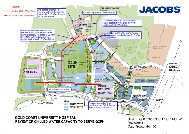
The maximum working load of the existing GCUH is 22.8MWr (based upon assessment of current use and estimated increases when the hospital is at full working capacity) and the maximum working load of the GCPH is assessed to be 3.8MWr. With a required redundancy capacity of n+1 (one spare chiller to allow maintenance as required) and a combined maximum load of 26.6MWr, the requirement is for 6 x 6MWr chillers. This is an increase of 1 from the existing chiller set and these additional works have already been allowed for within the existing plant room.
With the maximum capacities in mind, the specified parameters within which I have been told the heat exchanger must work are as follows:
- 3.8MWr max cooling
- Split of 6^C, entering the heat exchanger on the GCUH side at 6^C and leaving at 12^C
- Approach of either 1/2^C or 1^C, the temperature difference between the outlet temp of the GCPH side vs the inlet temperature of the GCUH side.
So before I contacted suppliers, i calculated the volume flow rate of the loops as follows:
Q = M C ^T
3.8MW = M x 4186j/Kg x 6^C
M = 151 l/s
Other considerations are the pressure drop across the heat exchanger, which will dictate the pumps required, and the pressure of water the heat exchanger must be able to cope with. I have been advised that the pressure drop would be in the region of 50KPa at best and should probably not go much beyond 100KPa. I have assumed the pressure to be in the region of 10Bar as I have no further information at present.
I contacted two suppliers, Alfa Laval and Swep, who provided options as follows:
| Ser | Description | Capacity | Approach | Split | Volume Flow Rate | Pressure Drop | Unit Cost | Quantity | Total Cost |
| MW | °C | °C | l/s | kPa | AUD | AUD | |||
| 1 | SWEP B649 | 4 | 1 | 6 | 160 | 100 | 13265 | 4 | 53060 |
| 2 | SWEP B649 | 4 | 1 | 6 | 160 | 50 | 14720 | 4 | 58880 |
| 3 | SWEP B649 | 4 | 0.5 | 6 | 160 | 13720 | 16 | 219520 | |
| 4 | Alfa Laval HEX | 4 | 1 | 6 | 160 | 100 | 108919 | 1 | 108919 |
| 5 | Alfa Laval HEX | 4 | 1 | 6 | 160 | 100 | 130698 | 1 | 130698 |
| 6 | Alfa Laval HEX | 4 | 0.5 | 6 | 160 | 224427 | 1 | 224427 |
Conclusion
Whilst the use of a heat exchanger simplifies maintenance ownership issues between the two hospitals, and the separate chilled water loops provide an element of isolation should there be any problems on the GCPH loop, that comes at significant cost.
The system would require additional pumps, again with an n+1 redundancy, to pump the water through the GCUH side of the heat exchanger, whereas if the chilled water is connected directly there is only one pump set required to service the branch.

The capital cost of the heat exchanger itself can be seen in the table above and is significant, added to that is the requirement for additional pumps to serve the GCPH side of the exchanger as shown in the diagram below. These pumps also have significant capital cost and there are also the associated maintenance costs to consider. There is also the added issue of having to house the heat exchanger and pumps somewhere within the GCPH.
Based upon these factors, I cannot see how the use of a heat exchanger could be considered a viable option, but at this stage I have just been tasked to source options. I will discuss with the PM as to the way forward.
USACE Design Phase – Initial experience
Though staying within the same overall organisation (USACE), my office has now moved 80 miles south. Instead of an hour car ride, it is now a 45-minute train trip direct to the front door of the 10-storey downtown office block, experiencing all the ”sights and sounds” of Baltimore en-route!!
I was initially placed in ”Civil Works” – involved with levee design, stream and coast rejuvenation, waterways, Hurricane Sandy relief ops etc. Some really interesting stuff, but projects were very long-term and I would see little opportunity for tangible design. There were several reasons for that being my initial placement, largely I think as a hangover from Matt Fry’s good works he did whilst he was there, but project opportunities have now changed. So with a few chats and explanation of my DOs I managed to take a swift turn to the right and move to the Military Design Branch.
The Design Branch is 70-strong, with several sections: architecture, structural, geotech, site development, elec and mech engineers with many sub-specialities within each section. The number of projects that the Branch oversees (design, specification write-up and/or review) is immense. At the height of the US Army Base Realignment and Closure programme from 2005, the Branch was only designing 3% of its projects…but the total amount of projects being managed was over US$2billion! Now, on average, the Branch designs about 13% of its projects – the remainder are contracted out and then reviewed by the Branch. $50 Million is about the present capacity for an in-house design.
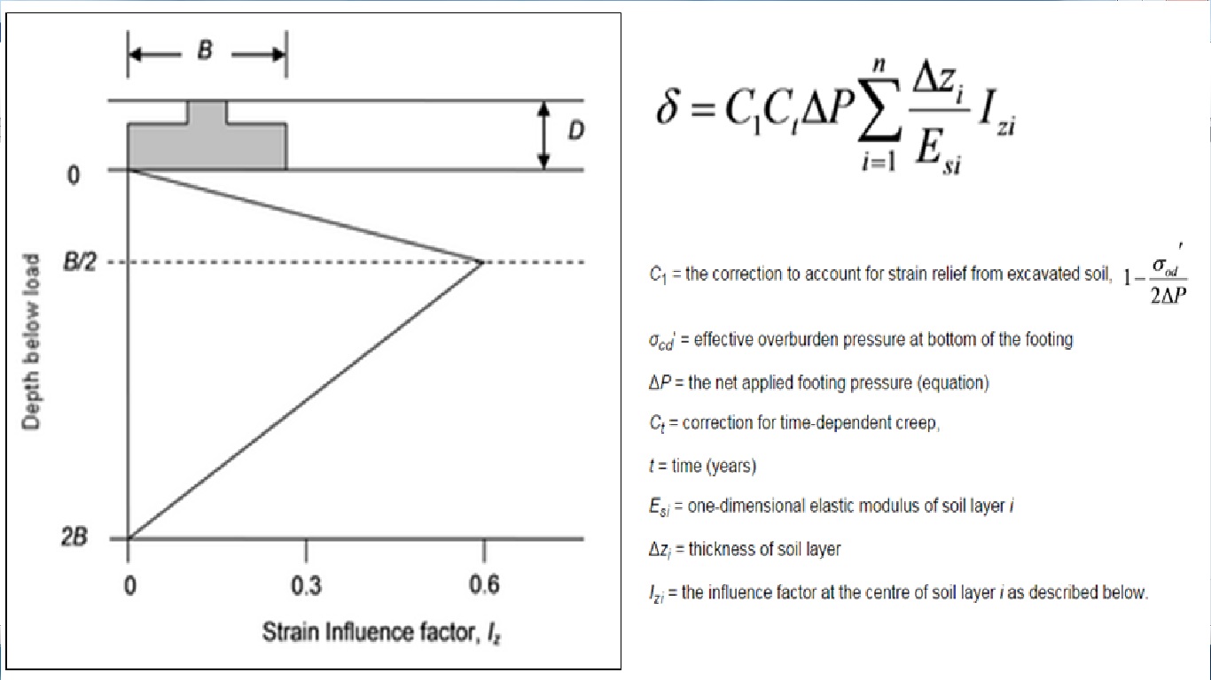
Now targeting my weaknesses – E&M, and Soils…I have already waded into a pump/lift station design, as well as preliminary shallow foundation footing sizing for a US Government testing facility in order to feed into the structural section for further detailed design in due course. The design experience gained in Phase 1 is starting to come to the fore – it took a little while to shake off the cobwebs, but it soon came flooding back (alongside much JM-note referral!). Being able to hold your own with certain specialists, gains credibility and responsibility quickly (that’s what I naively think so far!). To date, the shallow foundation design has been most challenging, particularly due to unit conversion (structural loading in ‘kips’ to name but one!…so I quickly turn everything back into the bosom of ‘kN/m2’), and then running through text books and new ACI codes. ULS design reverts to Terzagi for bearing capacity checks, taking q(ult) and dividing it by a FOS of 3 to get ‘net’ ultimate bearing capacity. For SLS checks, I have been directed to use the Schmertman Method – for those interested, it calculates settlement from layer stiffness data, bearing resistance as well as a time factor for creep (although the latter has had little influence). The method proposes a simplified triangular strain distribution and calculates settlement accordingly; once mastered with an excel spreadsheet, it has been quite a user friendly method to quickly manoeuvre parameters within.
Having attended several design meetings on other projects two things have already become quite apparent:
BIM. Or, the lack of it! There are essentially three different design systems worked on by a design team – Civil 3D by site development (outside the 5-ft line), Revit by mechanical engrs and MicroStation by electrical engineers. Though great for their various disciplines, USACE is admittedly way behind private industry when it comes to BIM. A huge amount of time is wasted with different disciplines coming together to overlay their programmes in order to deconflict and then redesign accordingly. Federal systems move slowly in every way – recruitment, IT uptake, project funding etc etc (I will be going on design charette next month for an armoury project, designated for congressional funding in 2022!!!).
Generalist vs Specialist. In-house design dramatically stretches the Branch – designs are chosen for this exact reason…to maintain design credibility. The Branch would quickly become generalists if all they did was design reviews. Conversely, as a ‘military’ generalist I have been able to save a lot of time for the 100% ‘civilian’ design Branch answering questions on Force Protection and general physical security that have heavily influenced military site design. They could do with a FPE ‘specialist’!
In short, I foresee this being a great experience with some interesting opportunities to hopefully continue getting stuck into and to keep topping up the DO’s!
