Archive
First Impressions: Muddy hole!
Prior to Christmas the Groundworks contractor took the level down to 150mm above formation and handed over to concrete contractor (PC Harrington of Southbank slipform fame). Concrete contractor took down to formation level, but had no intention to blind for an additional 3 days, despite direction to cover within 4 hours. Shear vane tests had been directed by the designer (Arup) which could not be conducted immediately, thus the contractor’s reasoning for the delay. Due to concern for the quality of the surface material at formation level – it’s London clay and tends to suffer from surface cracking if left to dry out and turns into an ice rink when wet – the contractor was instructed to blind immediately but leave holes for the test to be conducted. Seems strange that a specific test was specified other than “test for this property”, but it’s my first day and what do I know? I haven’t got a computer or a log on yet, let alone a clue what’s going on!
![IMG_0667[1]](https://pewpetblog.com/wp-content/uploads/2015/02/img_06671.jpg)
A real digger!
Day 2 and I witnessed a group of hairy Irishmen with their asses hanging out of their trousers (one for John) attempt to put a very large, prefabricated RC cage into hole. It didn’t fit. For 2 reasons: the hole was square, the cage wasn’t; and when the piles were cut down all the rebar was bent all over the place and wouldn’t fit through the spaces between the rebar. They got it in eventually but if Harry had seen how he’d have probably had kittens! It’s led to some cover issues. The rebar is touching the blinding round the hole in places, this probably isn’t an issue since it’s a tower crane base, therefore temporary, therefore the durability is unlikely to be a problem. But PCH are the problem children on site so we’re not given them an inch at this early stage. So the contractor will have to do some localised breaking out of the blinding to ensure correct cover, mostly since they have no idea what strength of concrete was used when they poured the blinding! They’ve learnt from it and the steel fixers will make the other 4 in the hole – sensible!
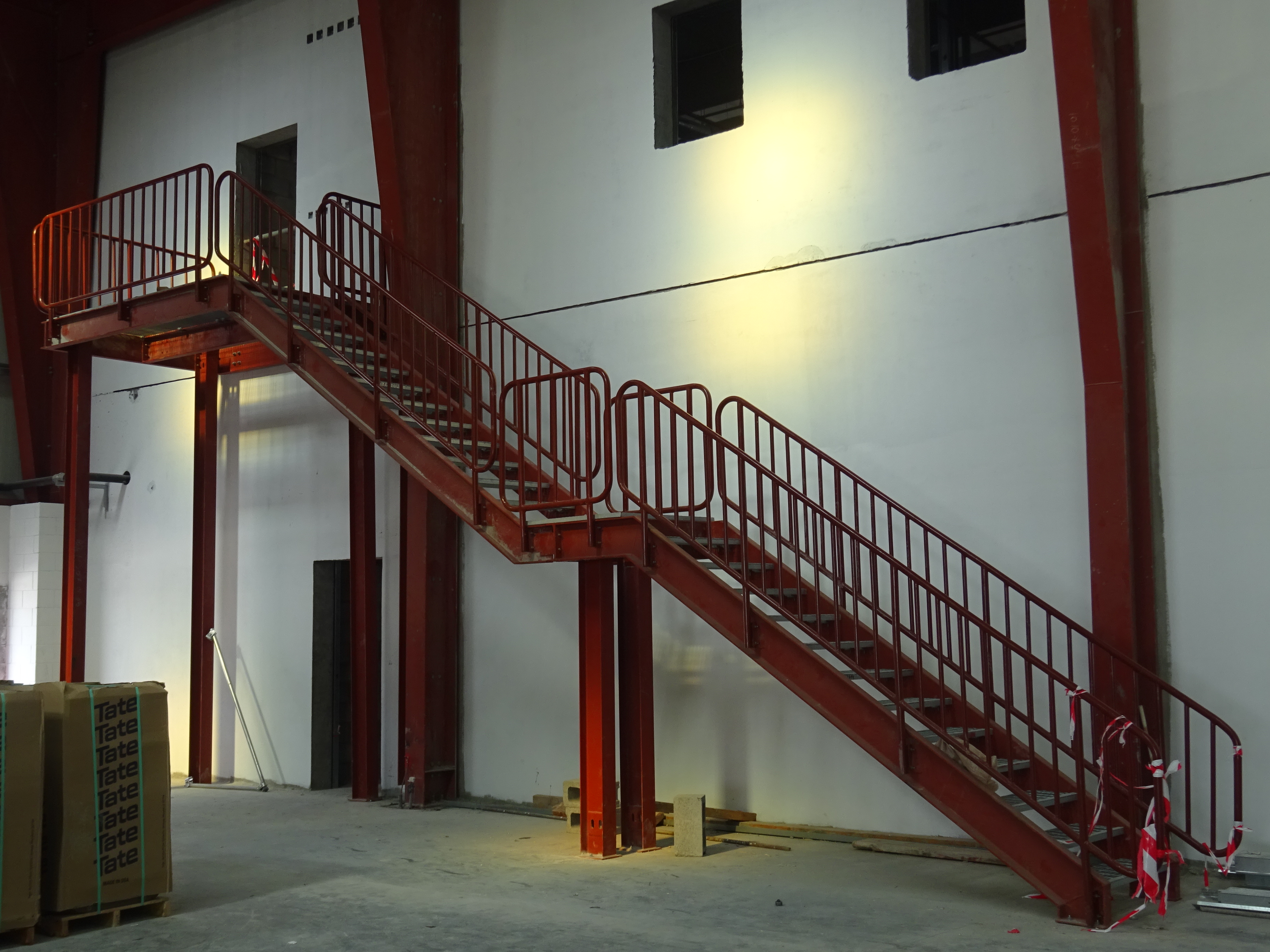
![IMG_0669[1]](https://pewpetblog.com/wp-content/uploads/2015/02/img_06691.jpg?w=300&h=224)
Tower crane footing
Today (Friday) I was sent onto site to hold the hand of a Geo Engineer from Arup (they must have heard of my fondness for quiche). He came to observe some shear vane tests on the foundation level clay prior to the blinding being poured. The minimum required value was 40kPa. The very lowest of our results was 120kPa. Does this mean the basement slab, sheet piling, pile shaft resistance and anything else that might have been based on cu is massively overdesigned? I tried to gently probe the area by asking questions, but didn’t get very far, the bloke looked about 12 and a bit scared that anyone had asked him a question with the word “overconsolidation” in it, all I got was that c’ was taken as about 25 (comment John?). Afterwards the Chartered Engineer on site asked me how I’d remembered things like Atterburg limits, I told him what we did last week and he looked horrified. I think I’ll be babysitting the Geo bloke every time from now on. Ahh well, at least it’s not making the brews!
![IMG_0660[1]](https://pewpetblog.com/wp-content/uploads/2015/02/img_06601.jpg)
Shear vane test
By the end of the week I finally have a computer, a log on and a McAlpine fleece, but still no clear idea of what I’ll be doing. Very TBC but it looks like I may be responsible for QA on Tower cranes, basement raft slab and, most excitingly, slipforming! Looks like I’d better dig back through Rich Hall’s blogs!
Bahrain progress Feb 15
All – I’ve added some updates from UKMCC Bahrain – Namely the roof, services, internal and external shots. Lots of photos for interest!
See roselliott.wordpress.com
Ros
UKSPEC and E5
All
I thought I’d share this little document with you for anyone looking at competence E5 and thinking ???. Don’t worry – some of the PEIs aren’t exactly sure however this competence is based around the Engineering Council’s statement of ethical principles (2014) so that’s the place to start. The document is a good read (E&Ms will know where the car chase is likely to be) and can be found at http://www.engc.org.uk/engcdocuments/internet/Website/Statement%20of%20Ethical%20Principles.pdf
Hope that helps those pondering this competence.
Design office blog 3
Submitted a tender to ICC (that I was bid leader for)
This was a request for tender that came through from a panel agreement that Jacobs have signed up to. The proposal was a fairly small one, with fees in the region of $30,000. It involved the checking of a preliminary design that the council had completed themselves, including some computer modelling, plus the design of some discrete elements in the stormwater harvesting scheme. This all sits within a larger flood mitigation project (outside of the scope). It was nice to be given this to run with as I’ve worked on a number of proposals now, but only concerned with the civil aspect of these larger projects. It allowed me to go through the review process and complete the tender documentation, helping to understand the elements that I’d only read about previously. This included everything form assessing the brief to submitting CV’s of the team that would complete the work, arranging the insurances and finally getting sign off from 2 of the directors (plus lots of other tasks).
I looked into the panel agreement a little further, as I’ve not encountered it before. The Local Buy panel is essentially a 3rd party organisation that matches clients (from local government) to design services and other service providers. There is a list of agreed rates that exist between Jacobs and the panel. In practice they just send out the requests for quotation to the companies on their list. Then they add a 5% fee. I can’t really see what value they add in the current market. The rates agreed were far above what is currently the market norm.
Completed stormwater sizing for the 50% design on Amberley RAAF base.
This was a small bit of design work to help out the engineers working on this project. First I worked out my design storm and the rainfall intensity, the Qld Urban Drainage Manual (QUDM) was the local standard to follow (as the land is owned by Defence they don’t have to adhere to local legislation, only federal, but they tend to follow it out of courtesy). I calculated my run-off areas from the CAD sketches, and picked some inlet positions. I took the design through to the sizing of pipes and inlets (this involved checking the flows captured in each inlet and what would carry on to another inlet).
Cost estimate for accommodation relocation.
This involved the client relocating dispersed accommodation assets to one location. The location to be removed has been sitting empty for some time. The new location was originally planned to be much larger, but was scaled back prior to completion. However all infrastructure was sized for the full camp (2500 men). The camp bore many similarities to expeditionary infrastructure, as each location had their own water treatment and sewerage treatment plants. Power was from the main grid and stepped down to 33KV where it came on site. There were then a series of HV and LV loops around the camp. The water and sewer mains were fairly simple to tie the new accommodation units into. I then received a rapid lesson on the comms and electrical infrastructure that would be needed from the team downstairs. I was just able to follow the lingo with the electrical kit, but started to get a little lost when it got to the comms. It turns out that each 4 man “donga” has fibre to it. It is then converted to copper for the individual rooms. I scribbled down lots of notes about the number of head end FOBOTs required and how the 144 core cable ran in a big loop from the main comms room. Each laundry unit was where the 12 core loops to the dongas were split out (there was another FOBOT here). All very interesting stuff I’m sure.
I got one of the drafters to put some quick sketches together on CAD. (see below)

The client was keen to know the cost as if it was below a certain value the move could be done as part of their operational budget. If it was too expensive it would fall to capital works and wouldn’t be possible in the current economic climate (commodities are currently suffering).
Recce to Melbourne (Puckapunyal) for a crossing design/assessment.
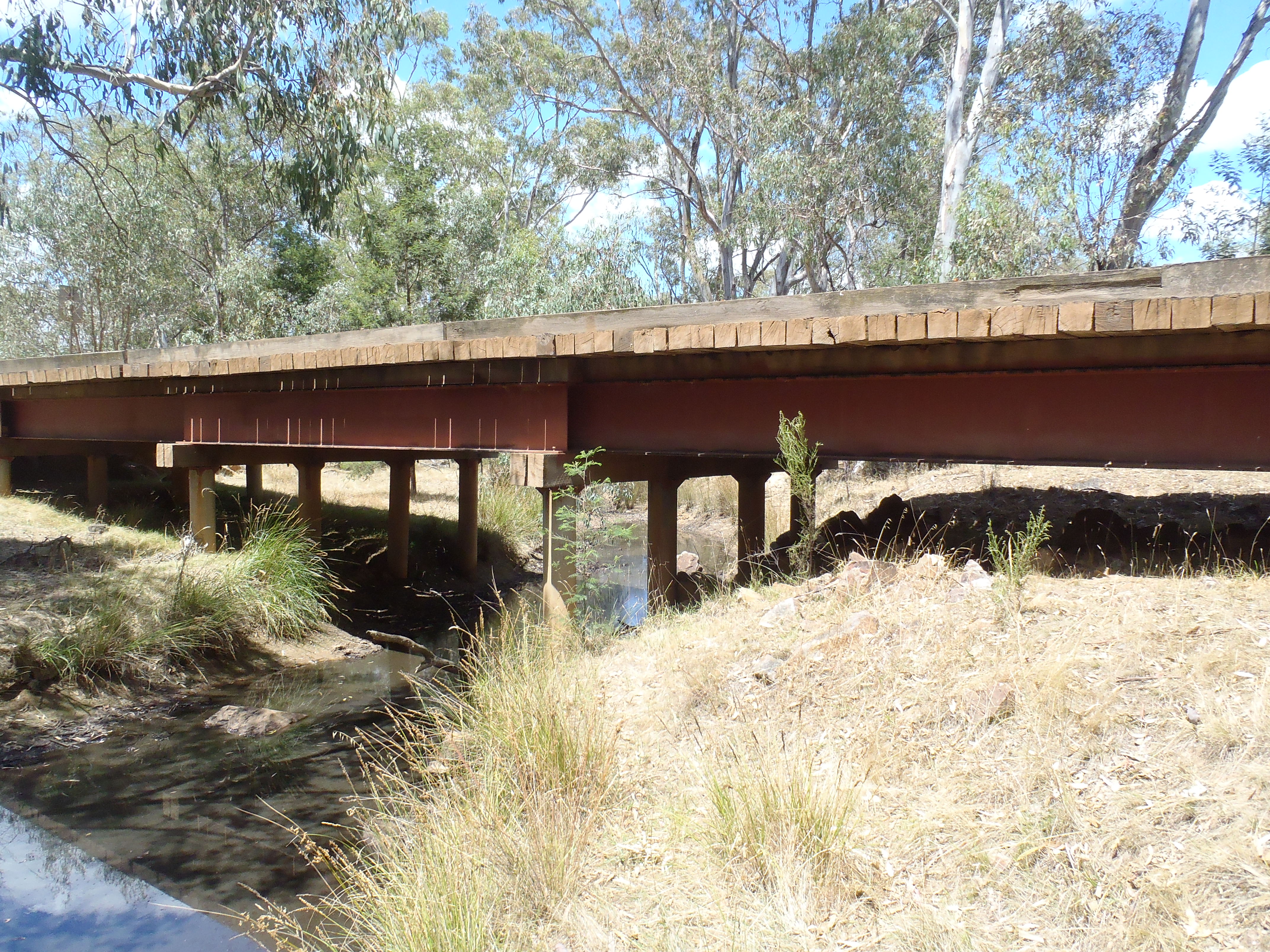
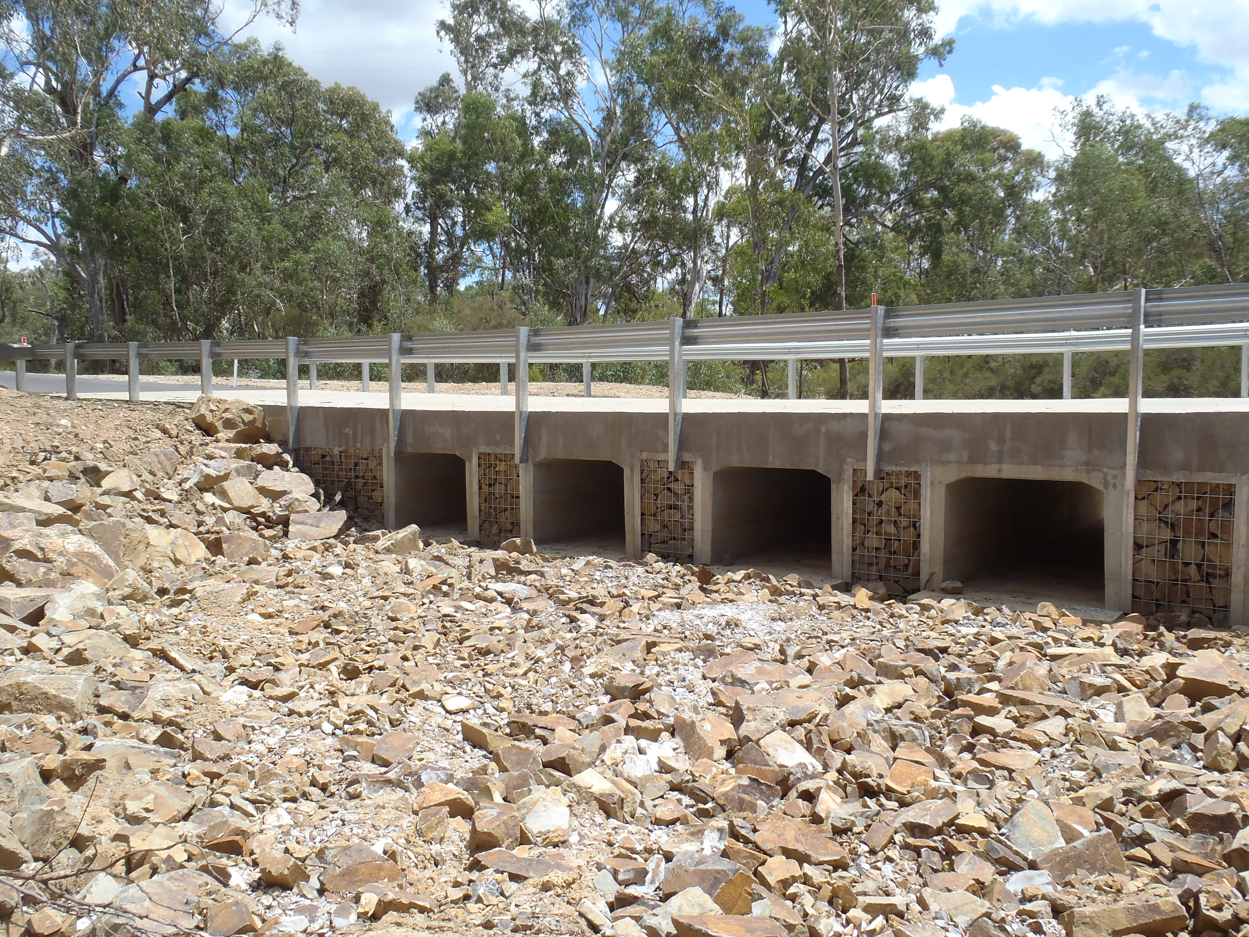
This turned out to be both a very frustrating project and very informative. At the start this sounded like a great little task, involving a free trip down to Melbourne. However I only saw Melbourne airport before heading North to Puckapunyal Training Area. This is the home of the Australian Army school of Artillery and their school of Armour. There is also an experimental weapons range tagged on the side for good measure. The background to the project is that Jacobs are managing the maintenance contract for the range. This year there was an underspend in the budget, so they are looking to squeeze in a number of tasks that were further down the priority list. On the training area are a number of crossings that have had their MLC downgraded significantly, see the photo below (looks suspiciously like a non equipment bridge). The aim is to install some new crossings to MLC 110T (wheeled). There is an existing design template that they want followed for these new crossings. Three existing crossings have already been built following this template on the training area and the client is happy with this style.
I was given the previous crossing drawings and the calculations that went with them. My task began as a review with some sizing of the culverts within the design (after finding the catchment size and calculating the design storm flows at the crossing points) On return to Brisbane I confirmed what I would be able to do for the team in Melbourne and set about deciphering the calcs. I completed my own check calcs in parallel to AS5100 (the Australian Bridge standards), the pavement was designed to a technical note published by the Cement and Concrete Institute of Australia.
Lessons learnt
Write down all thinking when doing calculations. It was really difficult to interpret this other engineers thought process. I am using educated guesswork to figure out why he selected a specific span to design to – it doesn’t match with anything in the design. It could also be old calculations from a previous job that were never updated – I just don’t know.
Understand clearly what you are being asked to do before starting a project. If the aim had been made clear form the outset, that a set of design drawings that could be issued for construction (IFC) were required, time and effort could have been saved. While I clarified what I was doing with the team in Melbourne on my return, they never stated their need for IFC drawings, or for any material to go outside of the company. This could be my own ignorance, but with hindsight I think they were after a quick and dirty, “she’ll be alright, just go build it”.
Unwillingness to move outside of comfort zones. This could be interpreted as people adhering strictly to the codes of practice and only working in areas that they are competent in. I see it as people not wanting to make the effort and take responsibility for a project. Going to other specialists for help when those unknown areas arise. This was put in the “too difficult” file by many until I pushed for the job to be taken. This could be due to the narrow field, but depth of knowledge many seem to develop. Only a few of the older engineers seem to have much in the way of cross discipline experience. Has anyone else encountered this? Is it more prevalent in the larger consultancies?
Transformer Blast Overpressure
The electrical team have a project to upgrade the electrical infrastructure within a communication network data center. Part of the scope of works is to create a new substation on level 10 of the building and install 2 new 1000kVA natural, air cooled transformers in separate fire rated compartments. The actual design and installation of the transformers will be the subject of a future works package.

I have been involved in the project both in the design of the ventilation system for the new substation and in checking the proposed design for compliance with Australian Standard (AS) 2067-2008 Substations and High Voltage Installations Exceeding 1 kV a.c.
The main cause for concern in the AS is that “where transformers are arranged in banks they should be separated by a fire barrier wall designed to withstand impact and blast forces in addition to its fire resistance”. The requirement to mitigate against blast is mentioned a further 2 times in the AS, but no detail as to how to mitigate for blast is provided. What we do know though is that if an explosion on one of these transformers knocked out the other, then the costs to the company in question would be in the millions of dollars per hour. One way or another we need to be certain that we have appropriately mitigated any risk.
Hoping for a quick fix, i trawled the internet for a blast over-pressure calculator. This wasn’t going to be that simple. I could find only one calculator that had been developed by Connell Wagner (Connell Wagner Arc Pressure Calculator), but the internet would only provide me with an image, so none of the calculations hidden behind. Furthermore, Connell Wagner were bought out some time ago and so I cant approach them for advice. I also found two UK Power Networks Engineering Design Standards which suggested the substation structure needed to be designed to withstand a blast over-pressure of 10kPa in a switch-room, and 5kPa in the transformer room.
In this case the transformers and their switch gear are co-located, suggesting a requirement for 10kPa. A quick check with the structures guys revealed that the existing slab on the 10th floor could at best support a dividing wall that can withstand 6kPa when the weight of the transformers was considered. We needed a more precise calculation.
I decided to set about producing my own calculator.
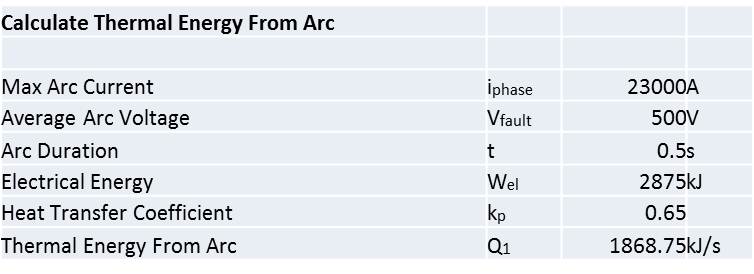
I found several useful documents that I used as the basis for my own calculation. Each of which appeared to base their work on a method developed by someone called Pigler back in 1976. Pigler was a much brighter man than I am but the general principles are as follows:
- The arc releases a certain amount of energy (Q), the proportion of which actually impacts the surrounding air depends upon a factor which accounts for the energy absorbed in melting the conductors and other losses.
- The arc energy causes an expansion of the room air (the first law of thermodynamics).
- That expansion increases the pressure on the structure.
Whilst this sounds simple, there are all sorts of factors to consider, such as the following:
- Is the transformer in a case or enclosure, and how does the expanded gas within that enclosure transition into the room?
- The transfer of energy to the air from the arc will not be uniform, and the subsequent rate of expansion will depend upon time and distance from the arc.
- The release of air from the transformer enclosure will either be through a vent or by a fracture in the enclosure.
- The impact of the arc energy on pressure is dependent upon where the arc occurs and what might obstruct air movement between the arc and the walls.
- Is there a vent provided within the room to release the pressure?
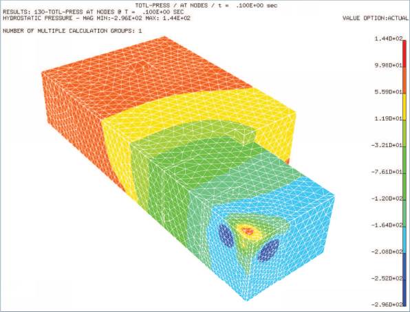
- A pressure distribution within the room will not be even, and there will likely be hot-spots as shown in the image below:

So, whilst Pigler’s method for determining over-pressure requires a PHD in maths and some computer programming skills, i recognized that I didn’t so much need an accurate answer, as an answer that proved that a 6kPa pressure was a worst case scenario. I went back to basics.
Where:
 and
and Then, for a perfect gas:
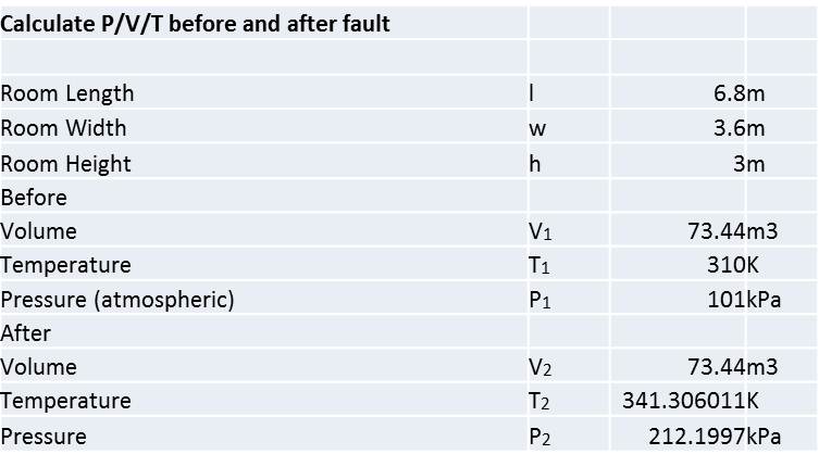
Where:
Using
These results suggested an increase in pressure of 111 kPa which was a lot more than the 6 kPa I had to play with so I thought i would see what impact a pressure vent would have in the room.
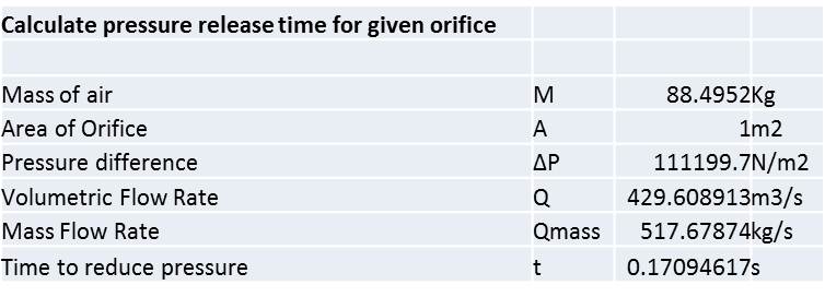
Where:
![]()
![]()

![]()
This suggested that the increase in pressure could be dissipated by a 1m2 vent in 0.17 seconds.
Essentially though, the process above only served to prove that this sort of calculation needed to be done properly, rather than assuming the arc energy influences all the air in the room at once, which it wont.
I called Siemens and persuaded them that they were in the running to supply the transformers. They modeled the parameters I gave them in some computer software and provided the following:

The result here was a pressure peak of 1.58 kPa with a 0.2 m2 vent (provided for by the ventilation duct in this case) which is comfortably acceptable in the substation.
What did I learn?
The chances of an arc fault on a dry transformer are very small, so small that this modelling would not be done for a dry transformer.
The chances of an arc fault on switch gear are also very small (approx 1 in 10,000) but the possibility is enough to model blast over-pressure.
The risk of explosion only really exists where the transformer is enclosed in a case. A sealed case, such as that on an oil cooled transformer allows the build up of pressure in a relatively small space, which can lead to an explosion. In a dry transformer open to the air in the room, the air will heat gradually and there is a much larger mass to absorb the heat. A small vent is sufficient to allow the dissipation of expanded air.
An explosion in an oil cooled transformer carries a high risk of fire. A dry transformer has nothing to burn.
Only use dry transformers inside buildings.
Pigler was a mathematical ninja, even surpassing the intellect of Brendan (I recon). Whilst I am sure even I could significantly improve upon the basic spreadsheet I produced, the array of factors involved in calculating blast over-pressure from an arc fault lead me to recommend that anyone who comes across this in the future just calls Siemens and you’ll get something back in a couple of hours.
