It’s a hole new world out there.
Site Two Fifty One
The aim of this blog is twofold. One – highlight what I am doing and learning on site, and two, discuss unforeseen ground conditions.
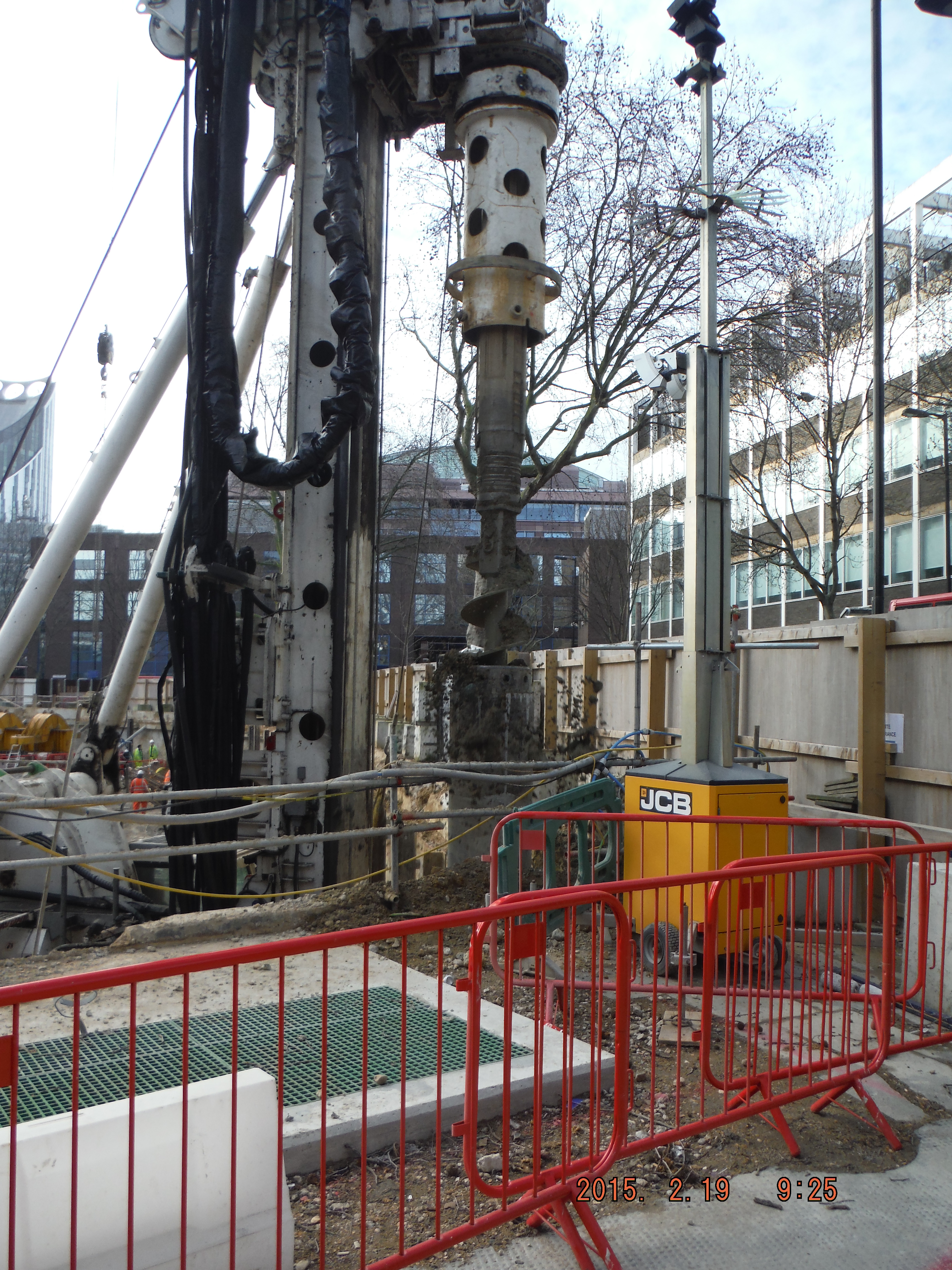
I arrived on site on 16 Feb and since then the focus has been on constructing the secant pile wall. The pre-existing site had one level of basement with an 800mm slab acting as the bottom prop. The slab is being used as the edge of the guidewall for the secant pile wall construction. The male piles, installed at the first basement level, extend to 26m depth through 6m of river terrace deposits and then into London Clay acting as an impervious cut off. The secant wall will act as a cantilever retaining wall when excavation to basement level 2 commences.
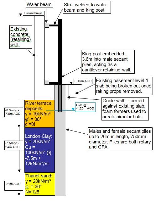
Cross section of secant pile wall, king post propped cantilever and ground model
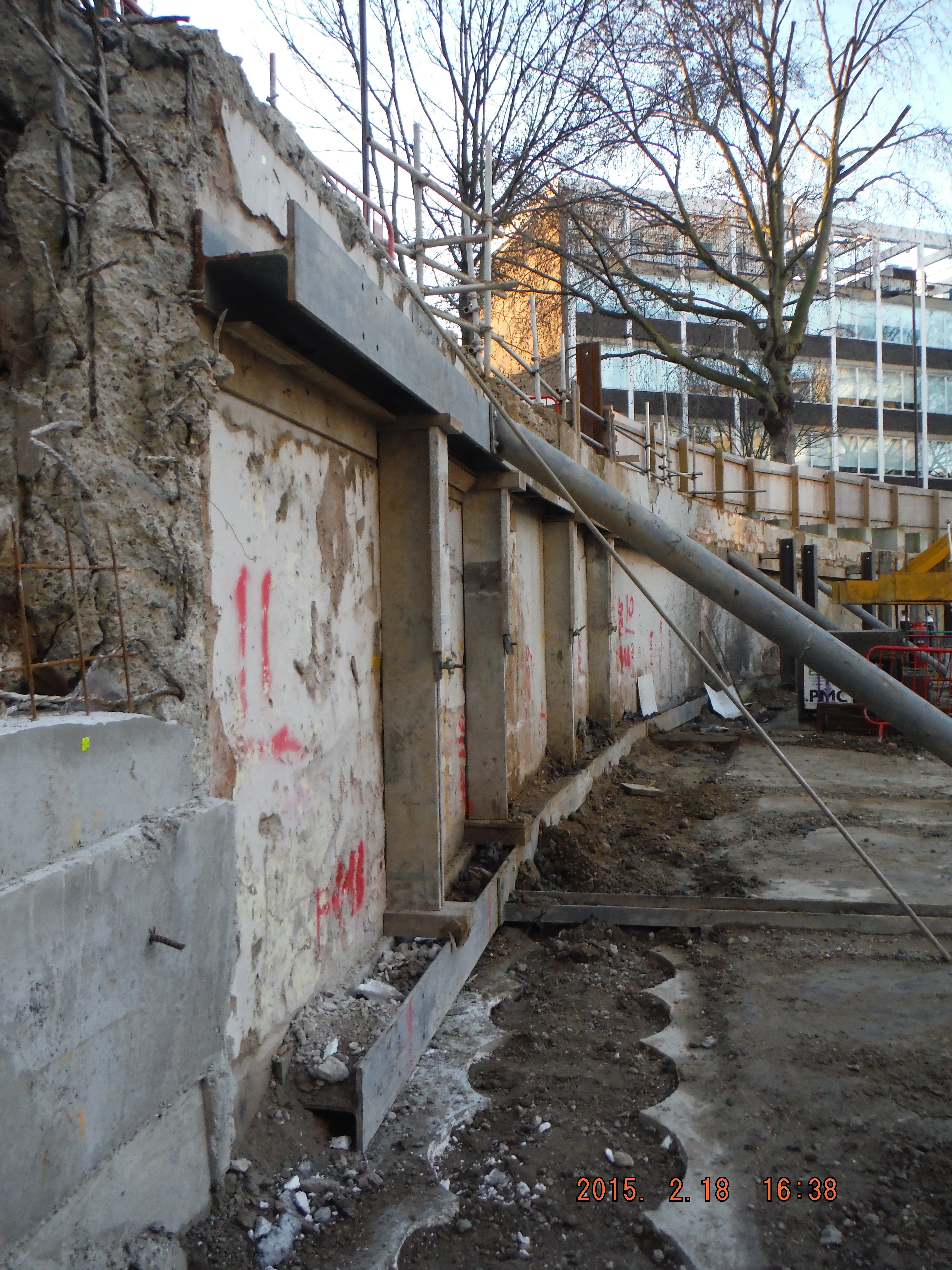
1. Pile Guide Wall (near ground) 2. Raking props to existing slab provide lateral restraint to existing wall (middle ground) 3. King Posts protruding from males secant piles to support existing wall (far ground)
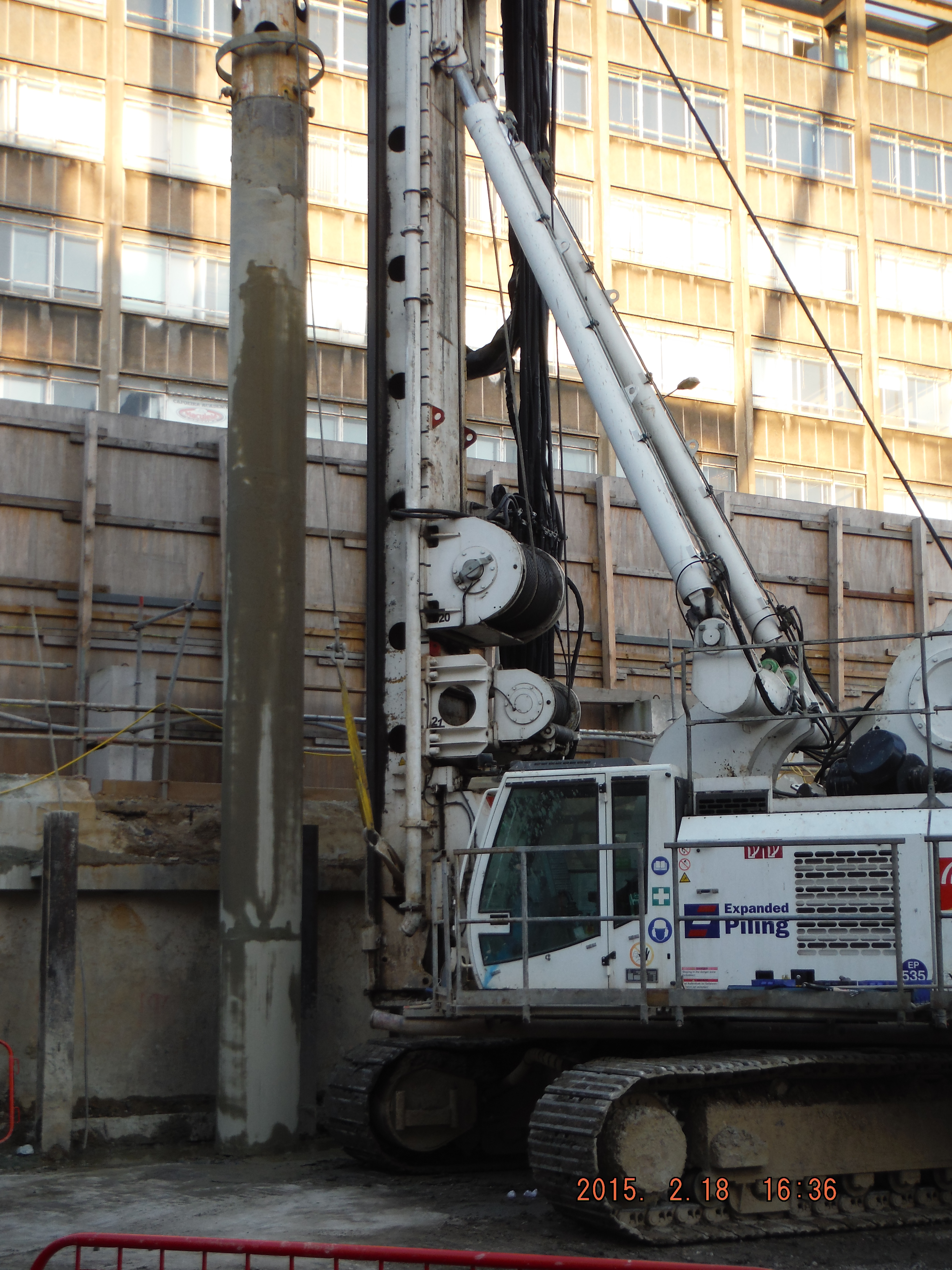
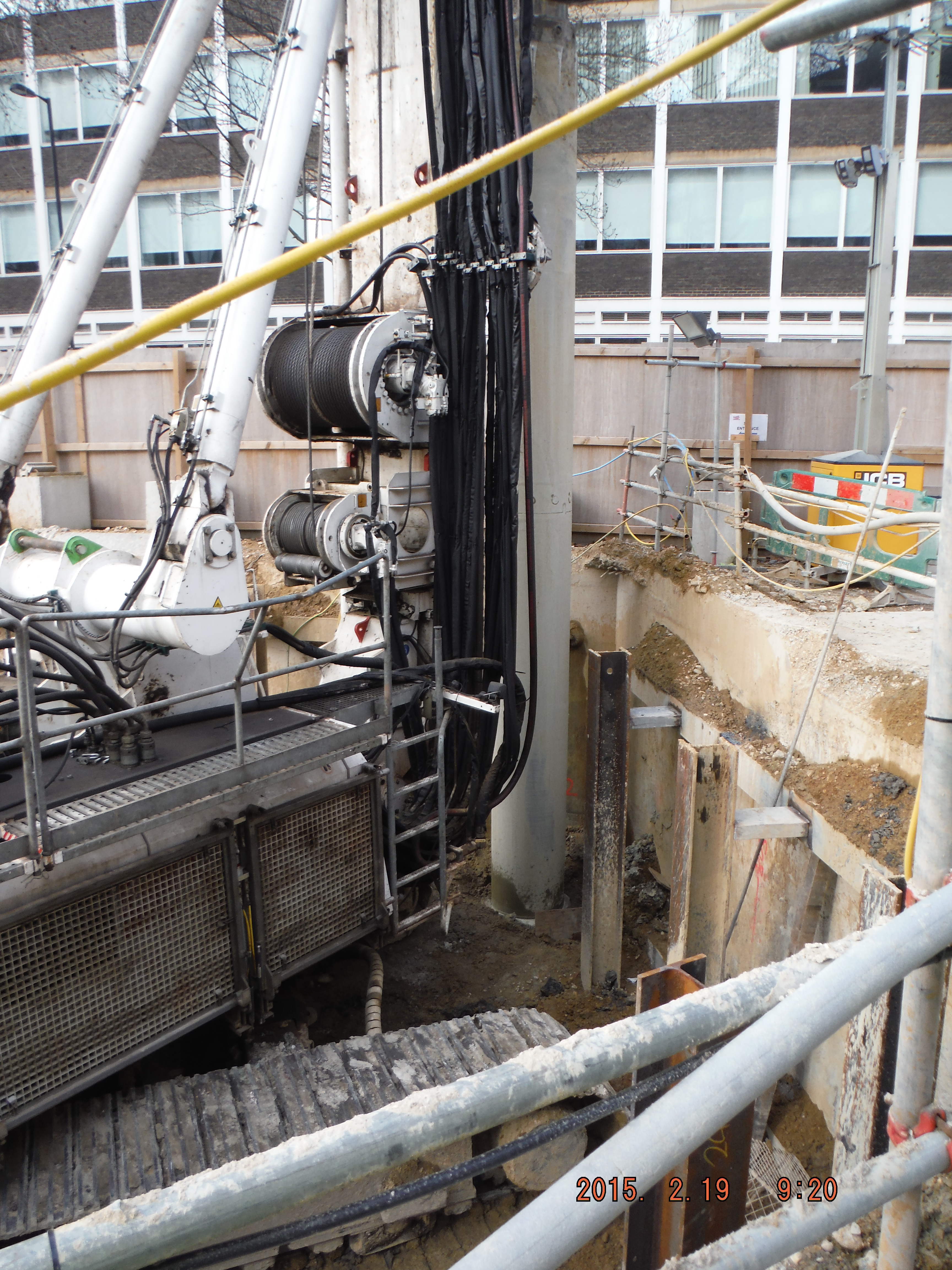
Piling. My role has being to coordinate the piling team to install the piles, specifically where to put king post columns to prop the existing wall up. This just requires thinking about which male and females piles to do to avoid doing them too close to each other and keep the pile rig put of the way of temporary props. Easy in open straight sections, a massive pain in the corners of the site.
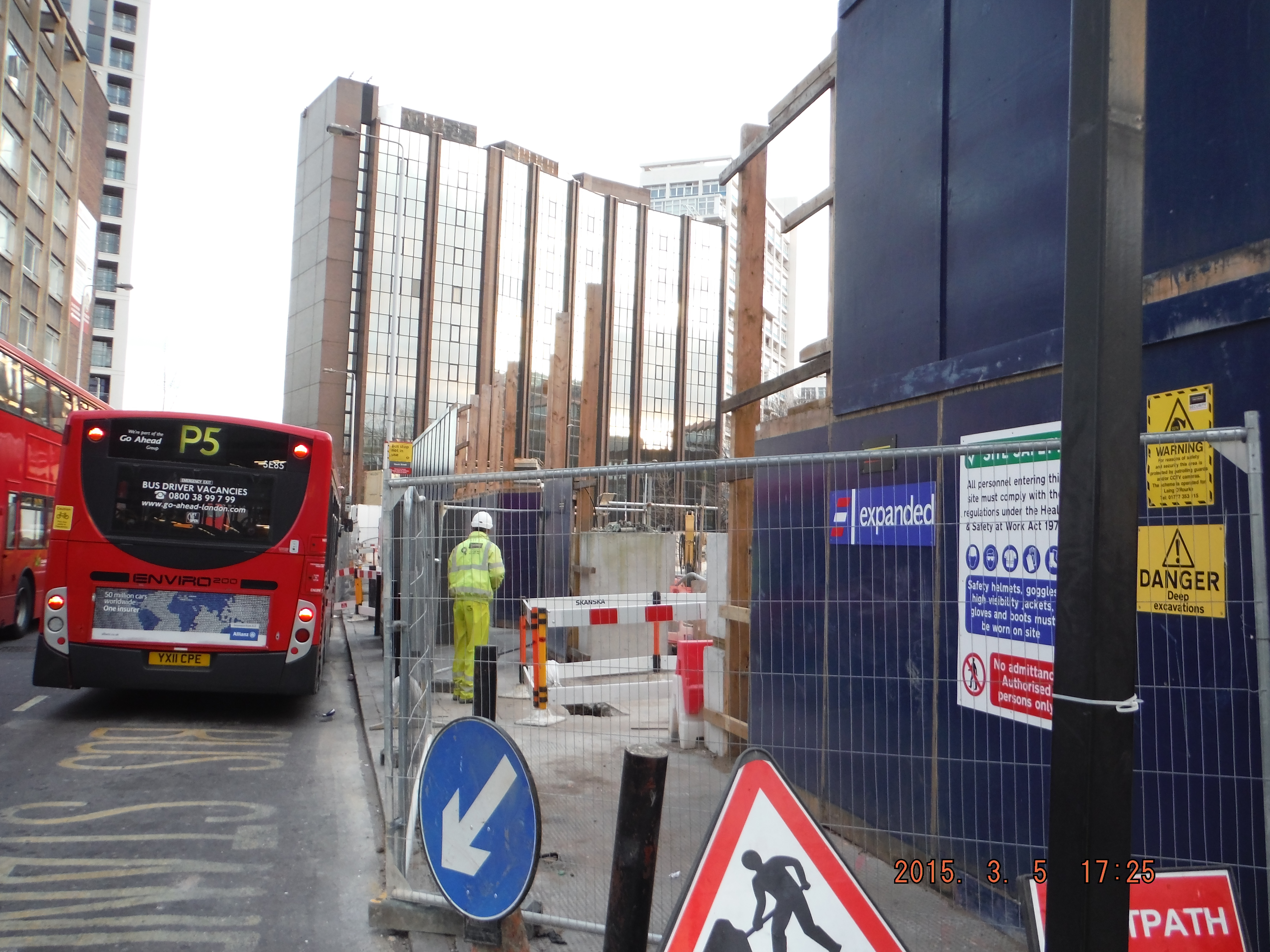
Site management. The project is at an early stage so welfare and office facilities are limited. The perimeter hoarding needs to be moved outwards and the live substation needs to be decommissioned after we have set-up a temporary one. Dealing with UK Power Networks and Skanska has been a challenge and I am now very aware of how to excavate around live services (Skanska operatives, however, seem less keen on digging by hand when within 500mm of services…)
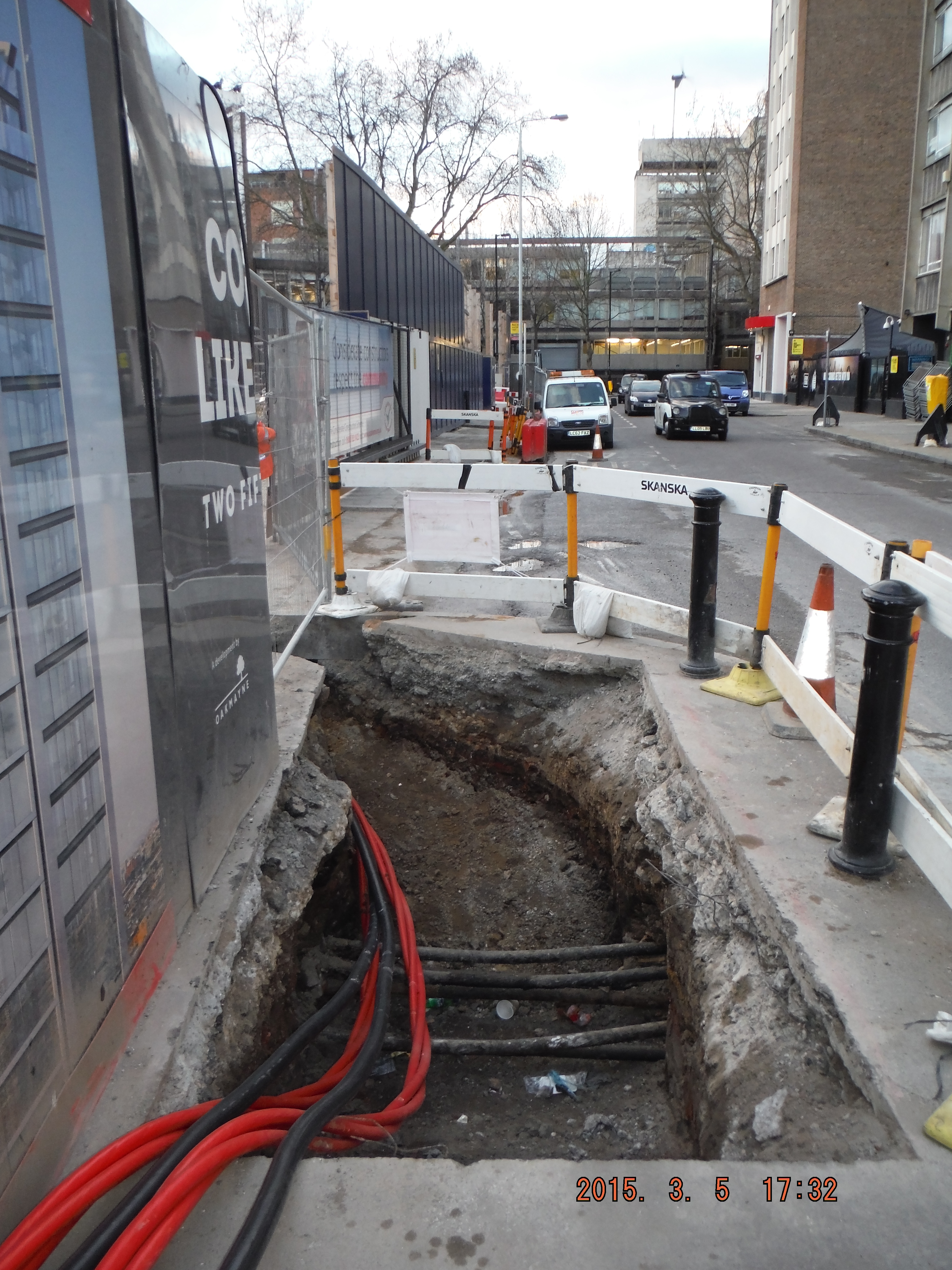
The hoarding move is progressing, but add in moving kentledge blocks close to a 3m deep excavation and a busy bus lane/rat run/cycle super highway there is room for error. Mitigation has been practical though – specific site safety briefings, inductions, lifting plans, segregation fencing and common sense, resulting in steady progress.

Right – hoarding moved within 300mm of blue cycle superhighway Left – heras fencing located where hoarding will be moved to. Note kentledge blocks and proximity to edge of excavation (H&S issues for slinger)
This week I have delivered my first tool box talk – pile mattress construction. Some good revision into the Design Manual for Roads and Bridges (DMRB) (thanks Richard), roller weight, type and width and I am about there. I have learned it is cheaper to order 6F2 (thanks for details of what it can contain Guz/Richard) on a “back load” as we are removing spoil daily. £120 compared to £160, thus making the project manager happy. I am also learning construction terminology: A skip “exchanged” means a fresh one replaces a full one and a skip “collected” is a skip taken away. Apparently “takeaway the full one and bring an empty one” is all too confusing!
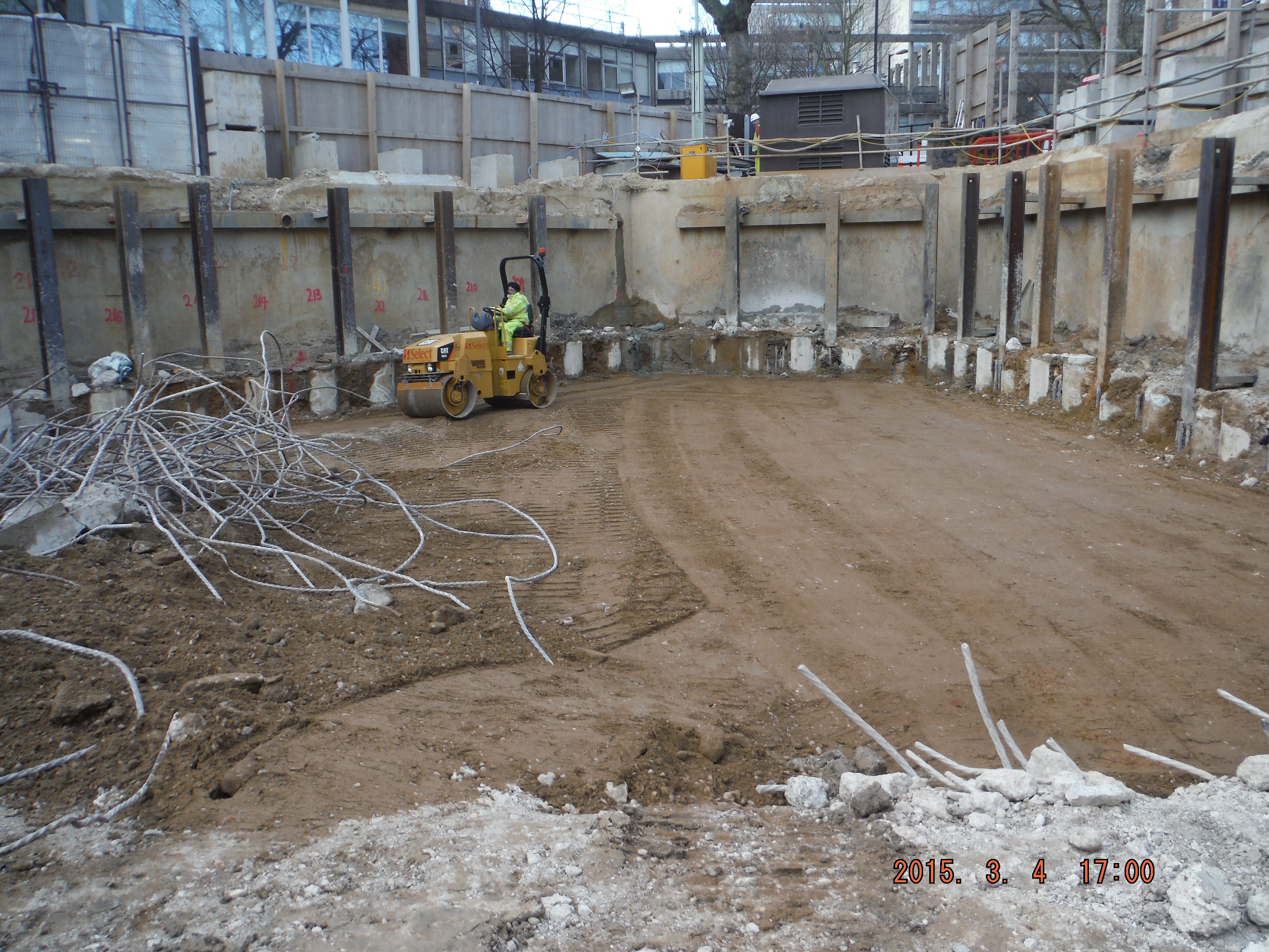
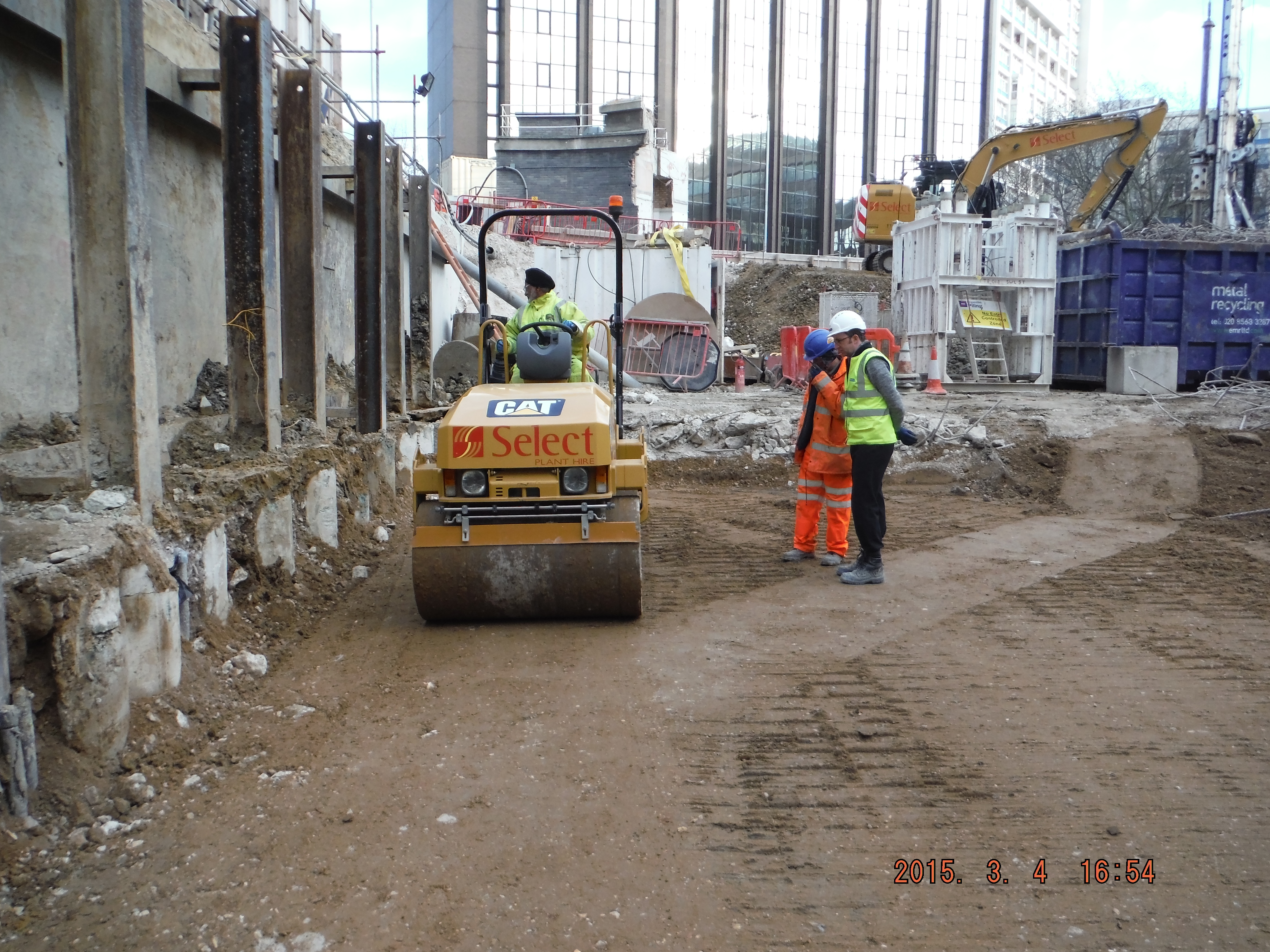
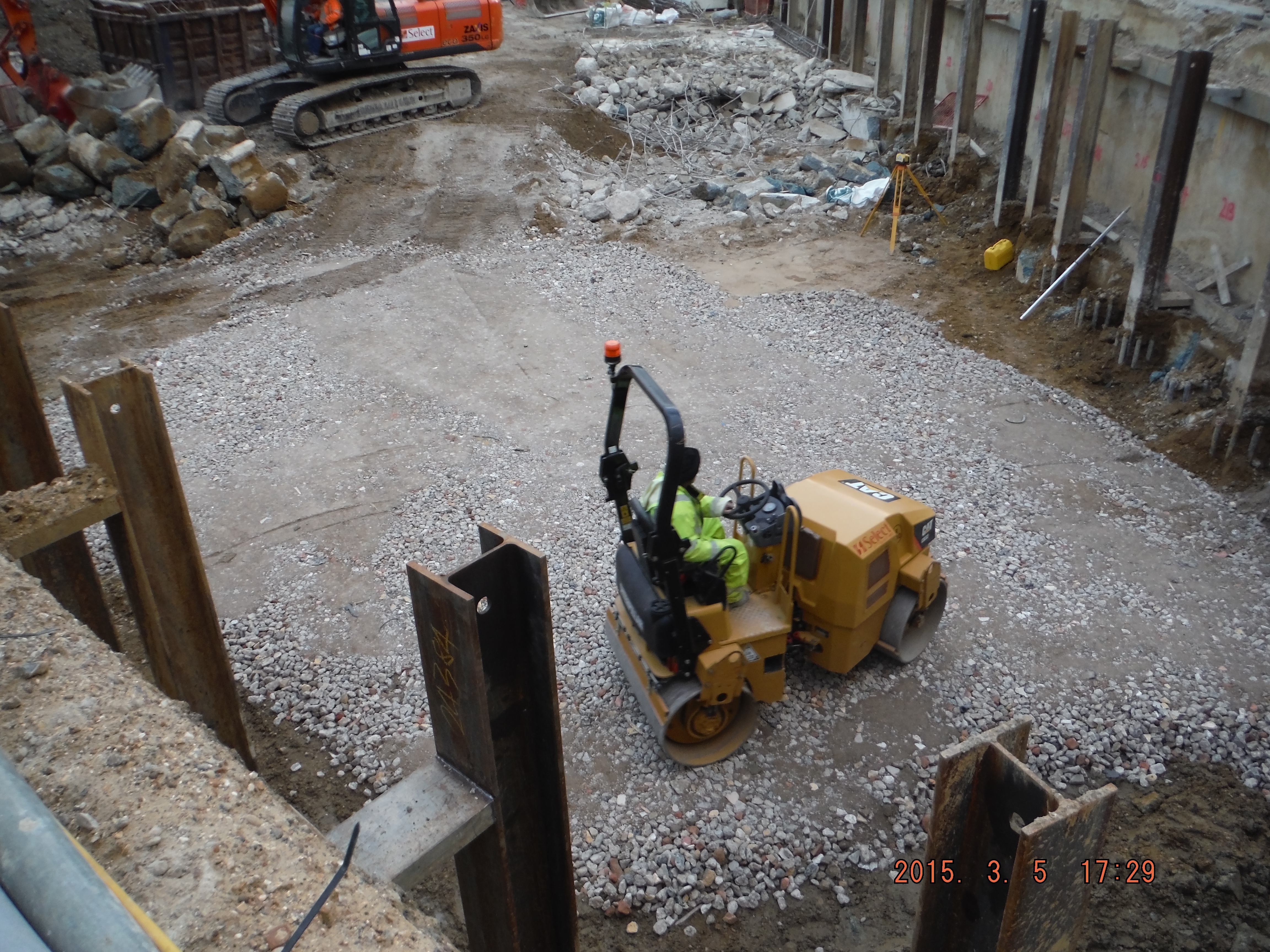
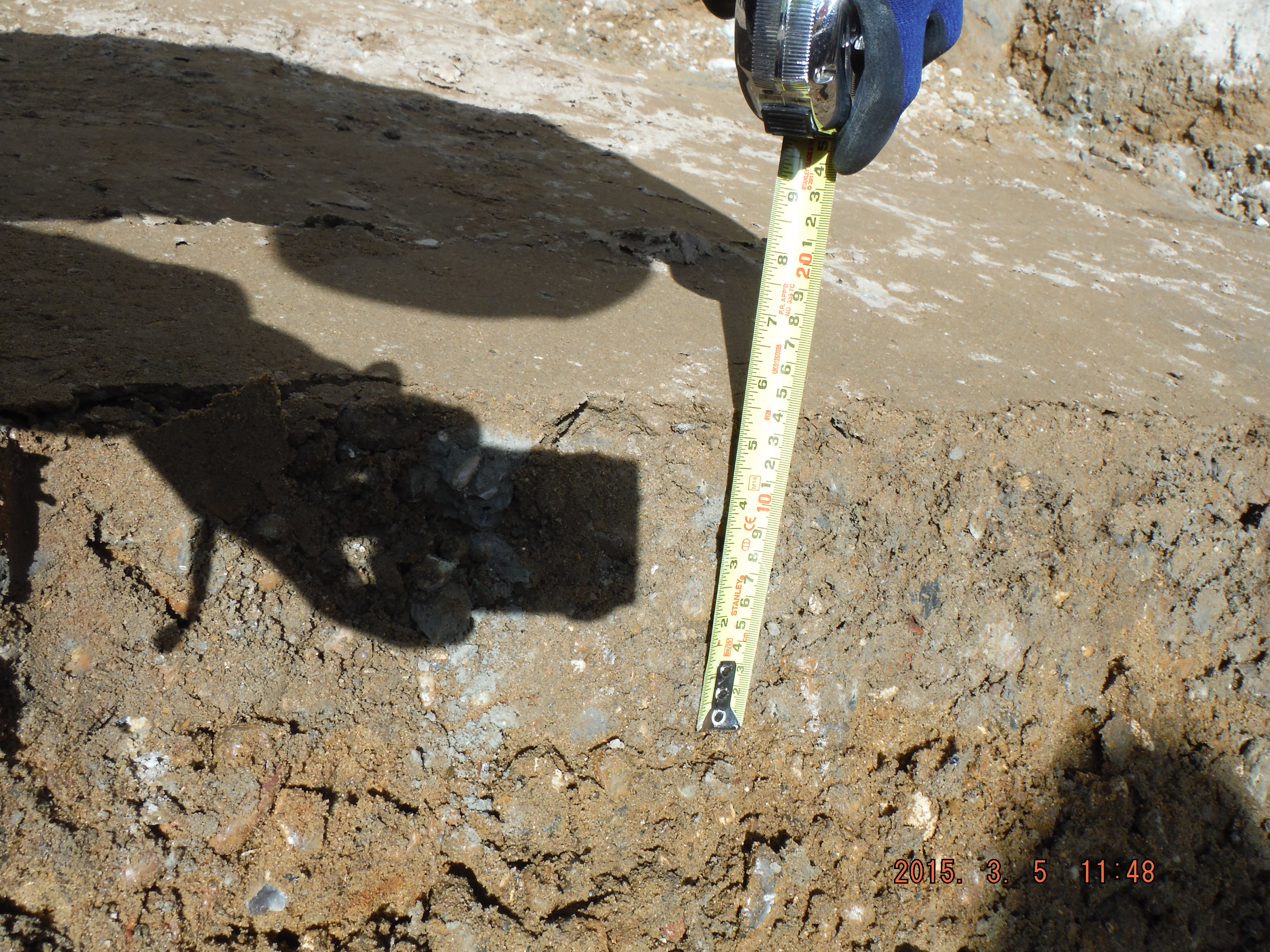
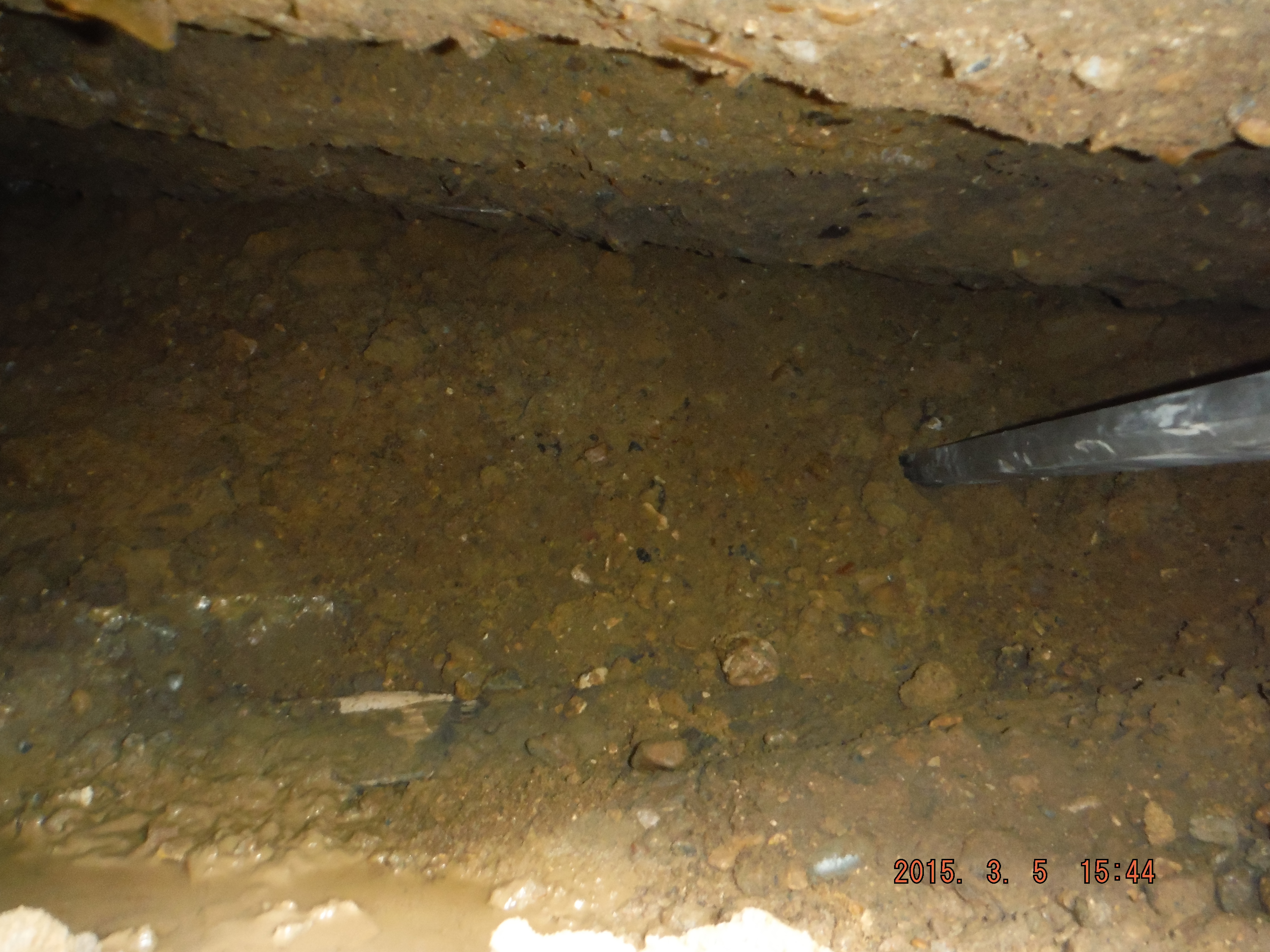
This photo shows compacted river terrace deposits. Rolled with vibratory roller – note depth of compaction – exactly 150mm @ 5 passes – as per the DMRB, now for the 6F2…
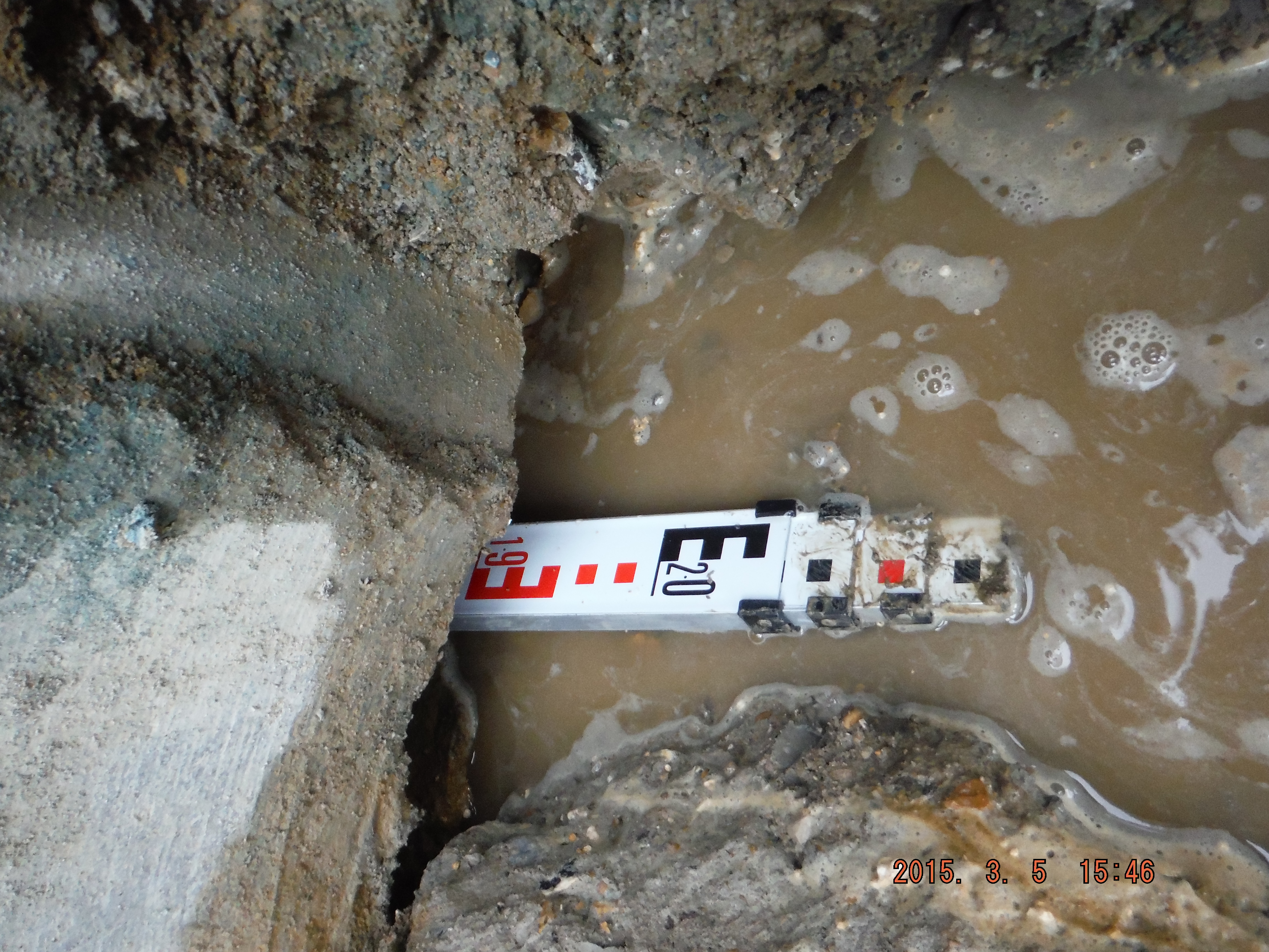
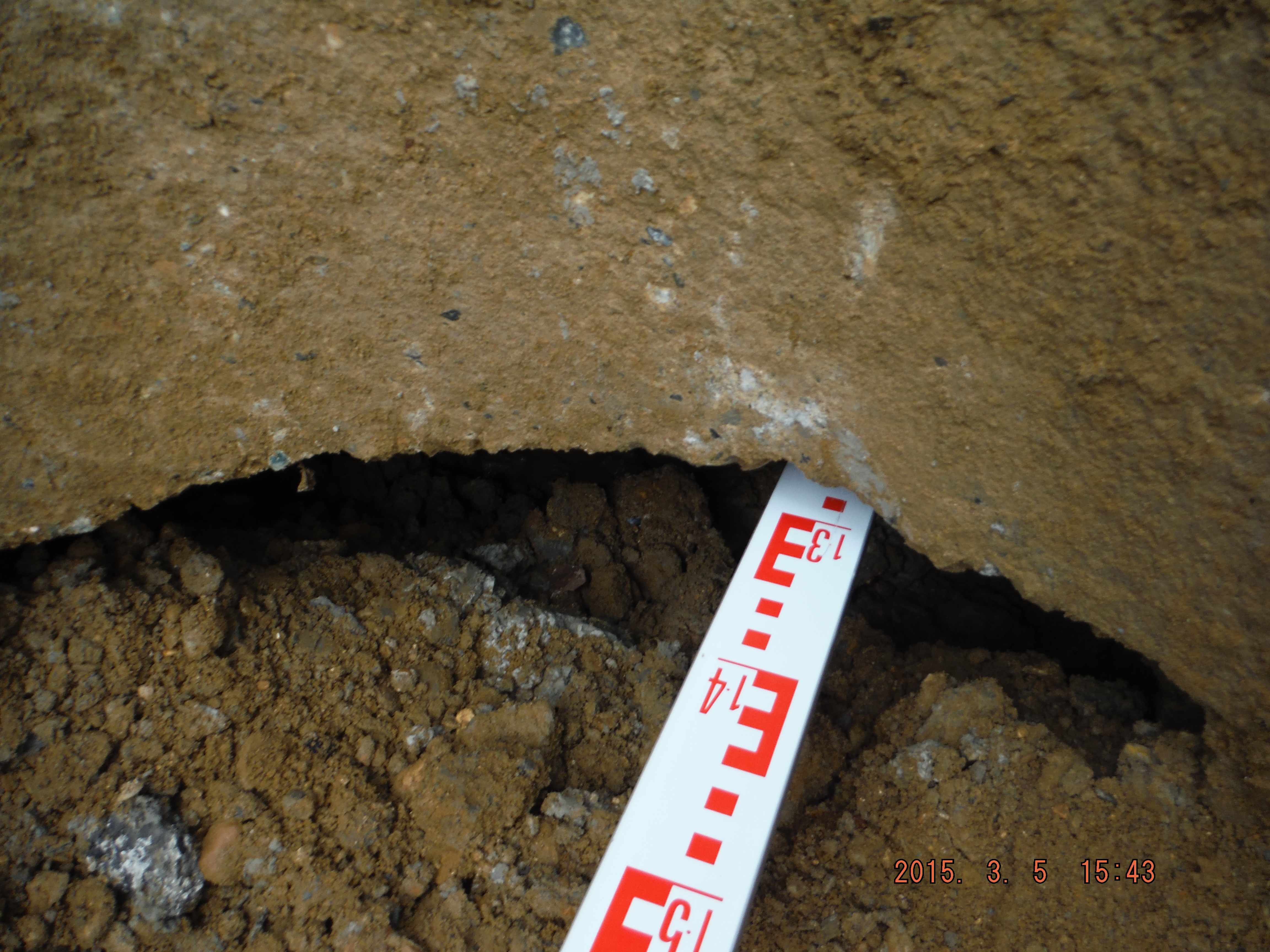
Now for the second part of the pun. After removing the pre-existing slab and some female pile heads it appears I have a floating wall. Well a wall being held up by lateral earth pressure resisted by the king posts and secant pile wall. The hole is about 300mm thick and 1.2 to 2m deep into the underside of the wall.
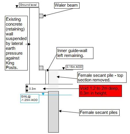
Cross section of existing wall and void identified above female pile which extends up to 2m underneath the wall.
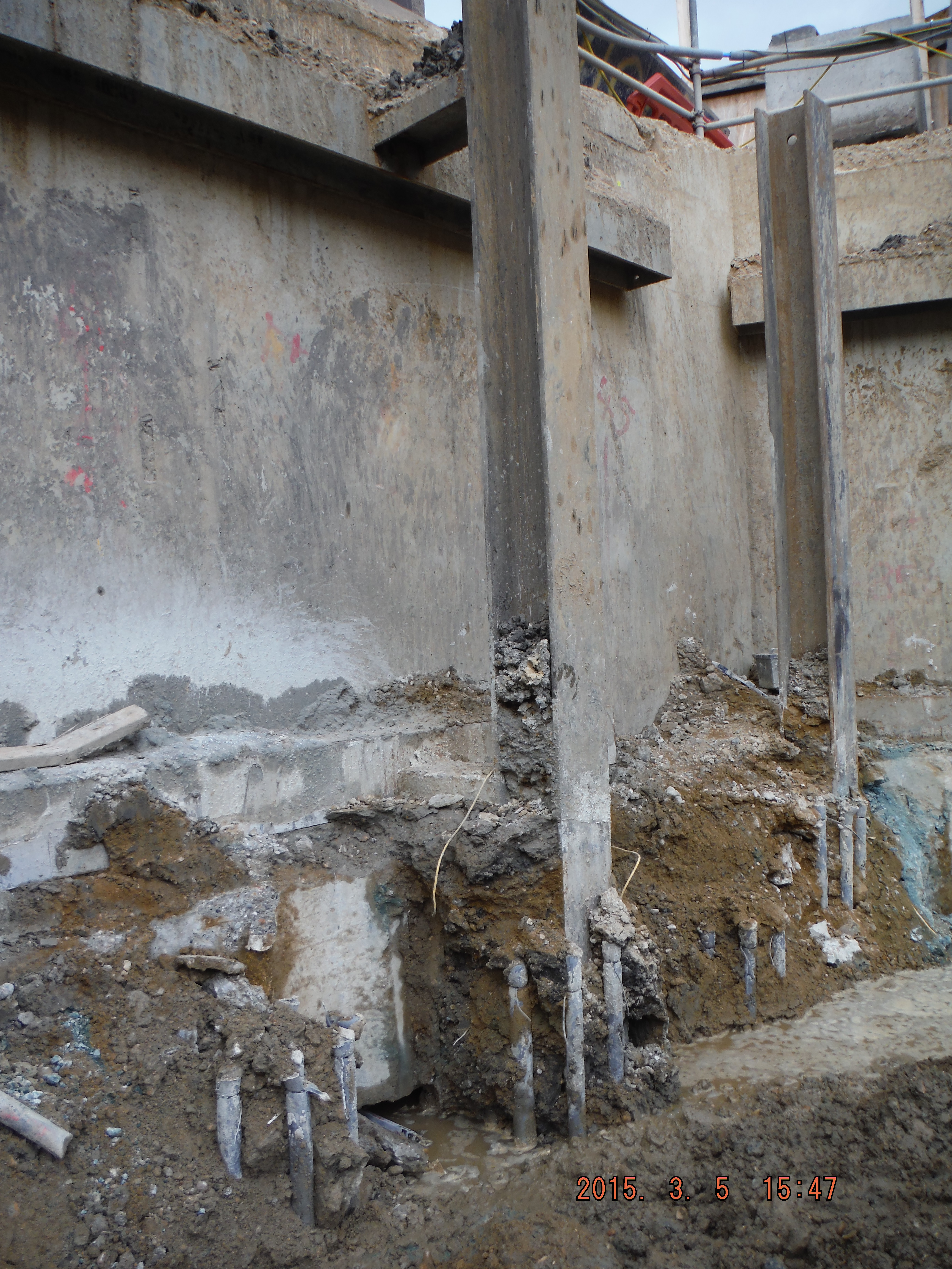
King post protruding from male pile. See void hole to left of king post, between the 2 sets of pile cage reinforcement.
Eventually I had planned to underpin the wall against loose debris in order to construct the capping beam. Looks like that won’t be a problem anymore. Looking into the hole it looks to have been there some time – perhaps the void formed due to water running next to the old slab washing the sand/gravel away (not sure where it has gone to though).
So what to do about the hole… Letter box fill – simply fill the void with concrete from above to close up the void. In the meantime there is already a weekly survey of the wall (mainly to check for deflection into the site, not subsidence of the wall) which has shown almost no movement so I am hoping that it remains that way for a few days longer. We only found the hole today so I am yet to resolve the issue, but as a consideration, if filling with concrete is done it’s roughly a volume of 1.4m (average) by 0.3m thick and extends along about 50m of perimeter so 21m³. Assume £100 per m³ and we are talking over £2000 at this stage and the void may well continue further around the site. Not huge but who pays, client, subcontractor or main contractor…

Thanks Damian,
I think what I’m seeing is a site that orignally had a superstructure bracing the top of a perimeter retaining wall, the superstructure was then removed and it’s bracing function was replaced by a waler and raking props. You have now replaced the raking props with piles and king posts and are removing the slab with the intention to go down further (two storeys?). You have established that the existing wall has been either undercut or built on poorly compacted material that has consolidated & settled away from it. You are keeping the existing wall into the futre and feel a need to support it from beneath. Why? What is the final construction detail for the site perimeter? Does it rely upon the old site perimeter wall for its integrity? Who is concerned about filling the void and why (usually a good indicator as to who might want to fund it). What is actually changing between the previous and future condition?
Hi Richard – The plan is to excavate one storey further (so two storey basement total). The existing wall is being kept because it acts as a retaining wall and avoids having to put any additional retaining structure behind it. The king posts and struts bracing to the waler beams are designed for the horizontal force generated from the active earth pressure behind it. The struts are not designed for the vertical shear force being applied through friction – it is now apparent that is how the wall is being held up and therefore filling the void will transfer the vertical friction force to ground. This needs a free body diagram but it seems blog comments cannot have pictures inserted. After overcoming the embarrassment of a units error regarding the wall monitoring, it appears there is about 1mm of movement downwards a week, therefore monitoring has increased to a daily survey. Additionally all costs (labour, equipment and materials) associated with the void remedial works are being carefully captured and, I think, are heading towards the client…
Thanks – understand the issue now. Also, if you scan a sketch in your should be able to append it or insert it into a blog.
Damian
An excellent blog and some stuff for CPR if it crops up. Keep up the good work
Regards