Condors, Piling Methods and Bomb Hunting
Site Two Fifty One
I’ll reflect on 3 points this week.
1. Sensible Health and Safety. This week’s Monday morning was more “Monday morning” like than any other – the busiest day on and around site to date. PM on leave and Project Engineer arrives at 9.30am (site works start at 0800). Typically muck away lorries, UXO survey team, slab breaking, pile rig conversion (rotary to CFA), perimeter hoarding move, substation re-routing and traffic management all collided at once. Add in the client’s representative visiting and an already confined and cluttered space and you have issues. Unfortunately the UXO survey team arrived late, muck away trucks got stuck and converting a pile rig needs loads and loads of space. This inevitably started to cause chaos and not just the site was becoming unmanageable, the roads around the site perimeter were getting blocked. This was the time to take the condor moment: step back, think and act. I chose not to and felt the client’s representative needed to be briefed. I missed the increasing hazards and did not take control. Shortly arrived the Project Engineer arrived he stopped the works (not for long because it just needed a few composed minutes to sort things out), cancelled further muck away, and installed new walkways to make safe passages between work areas. Simple stuff and a big lesson learned for me to then reapply the following day when the situation changed again.
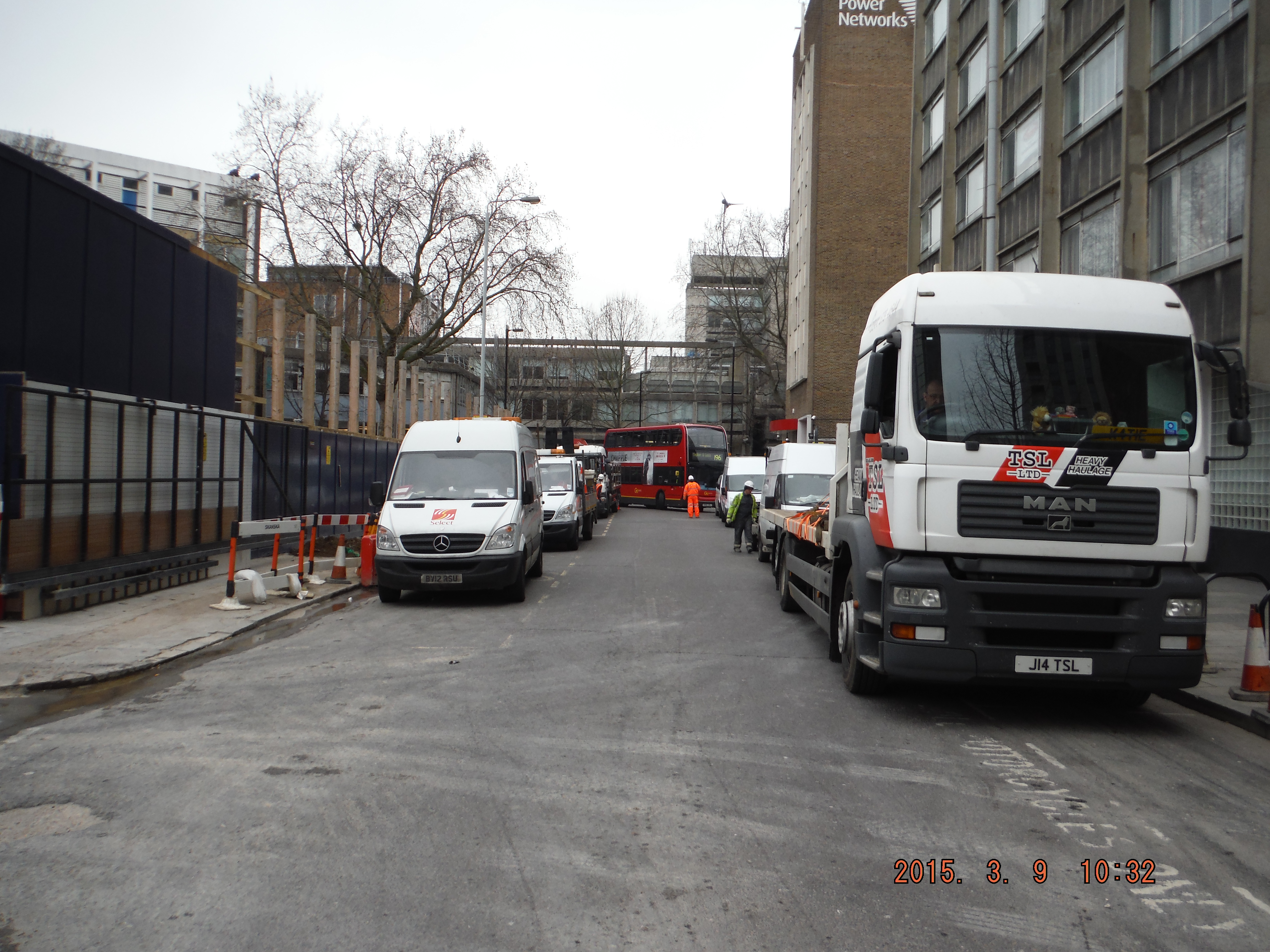
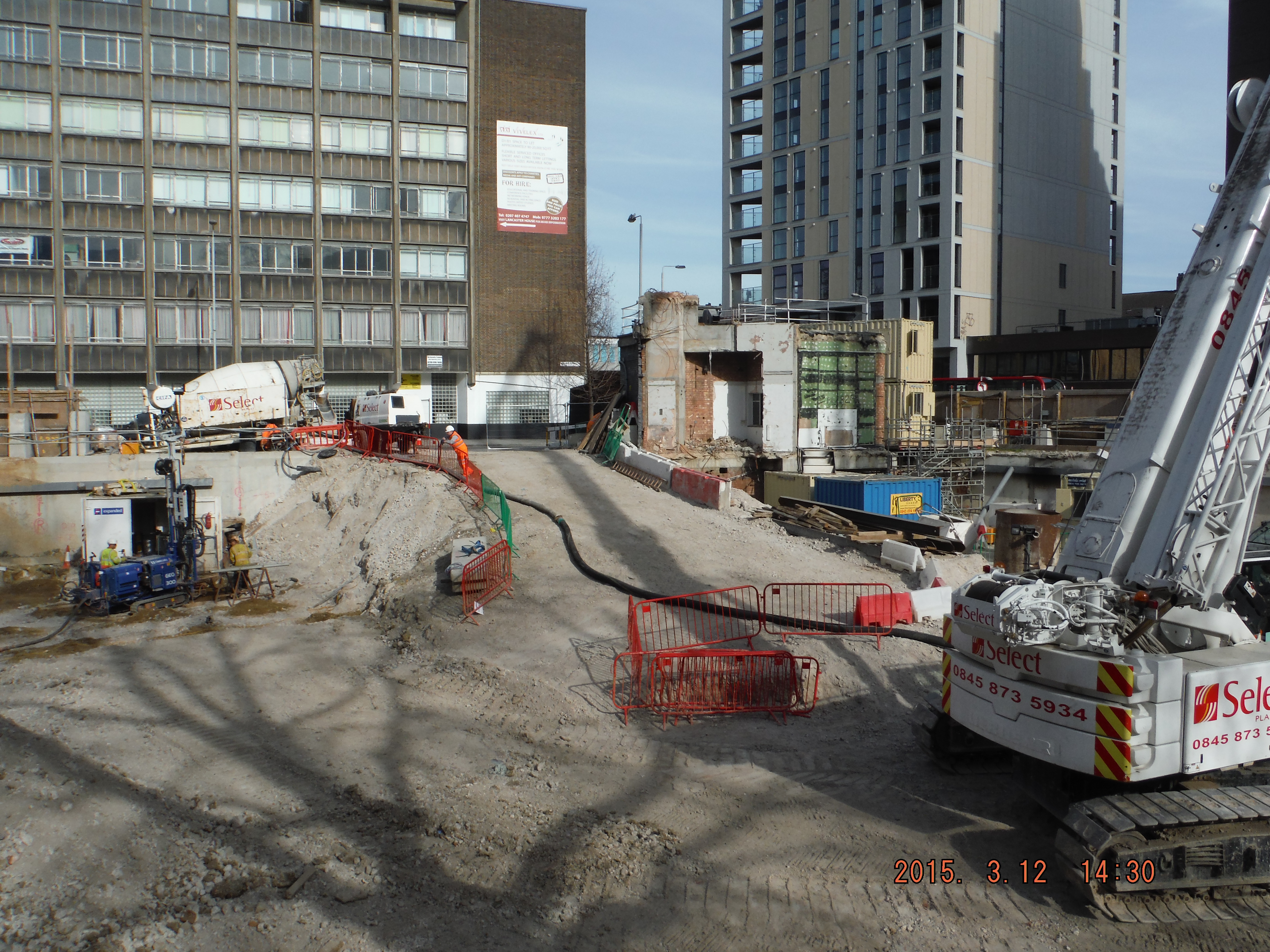
Site perimeter, Gaunt Street, choked with site vehicles. See high-ab arm at the back and the London bus attempting to get through.
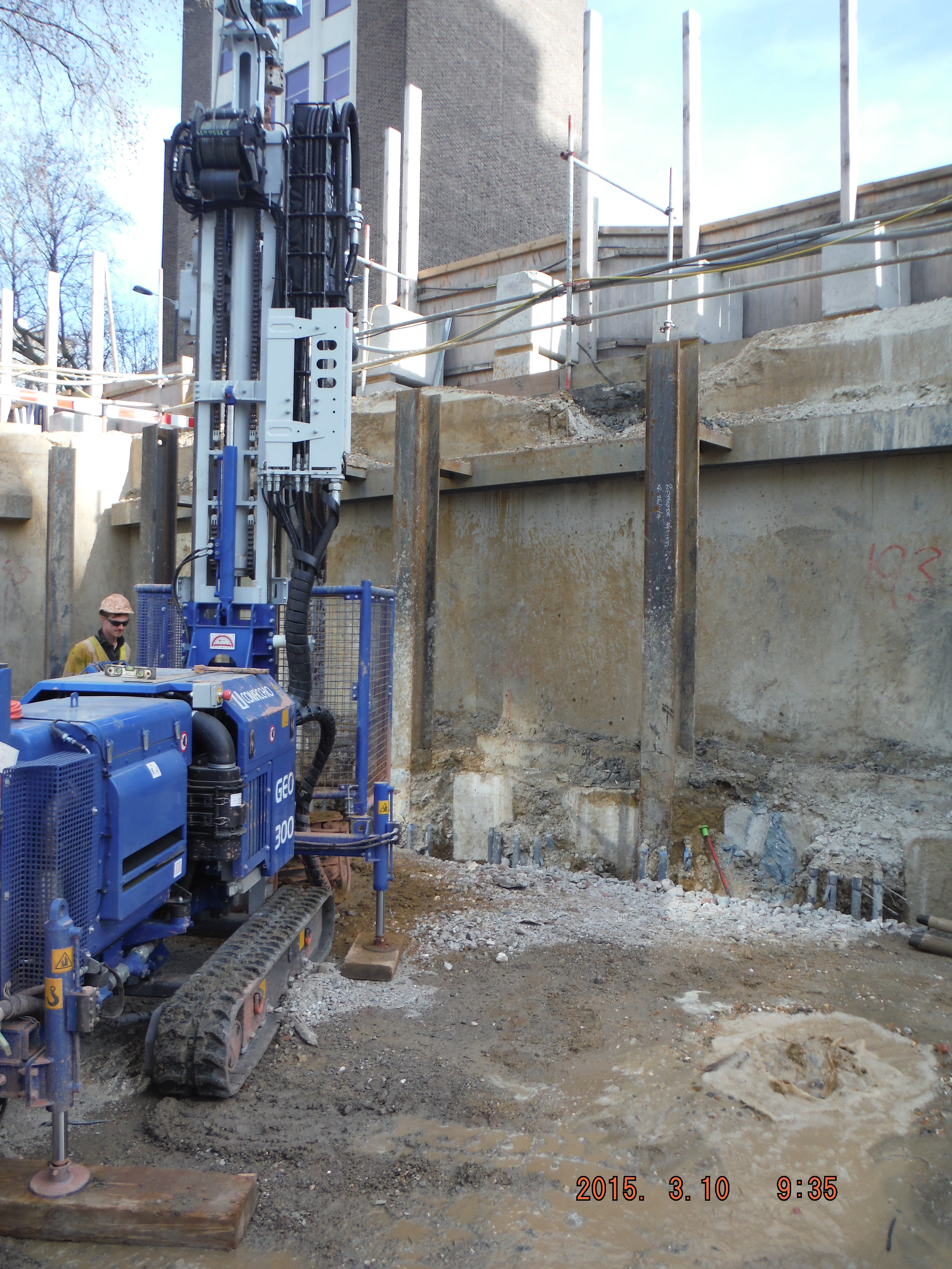
Site in overflow: slab breaking, excavation, skip exchange, deliveries, piling and UXO.
2. Pile type, Rotary to CFA. Some reminders for me/anyone who is doing either type of piling in the future. Firstly, allow 3-4 days, not 1 or 2.
Rotary bored (replacement). This is where the casing is bored into ground and a rotating auger is used to excavate the soil within. Casing keeps the hole open and makes a pretty neat pile. This method struggles to work at 38m depth and in dense sand – hence the change to CFA.
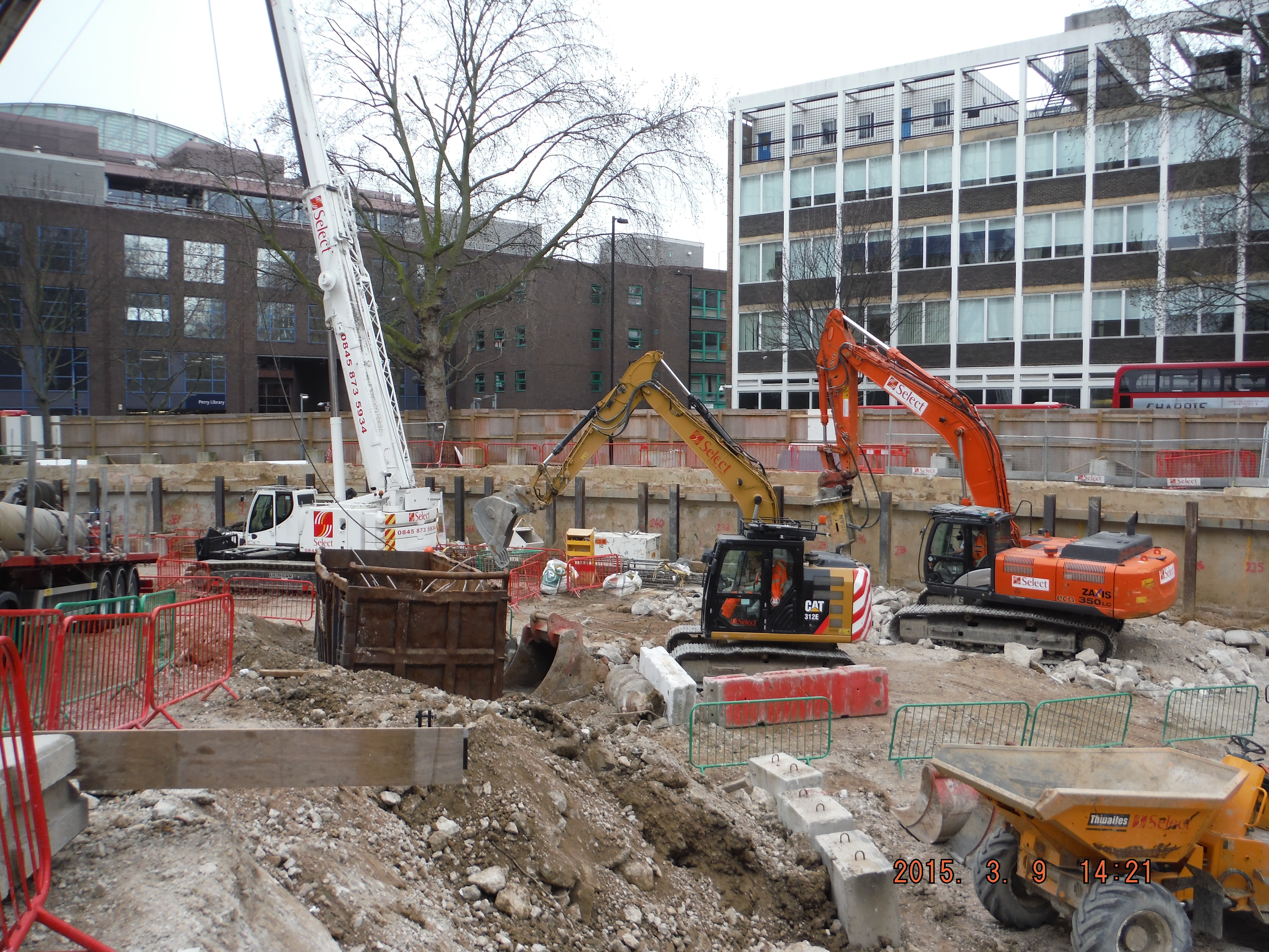
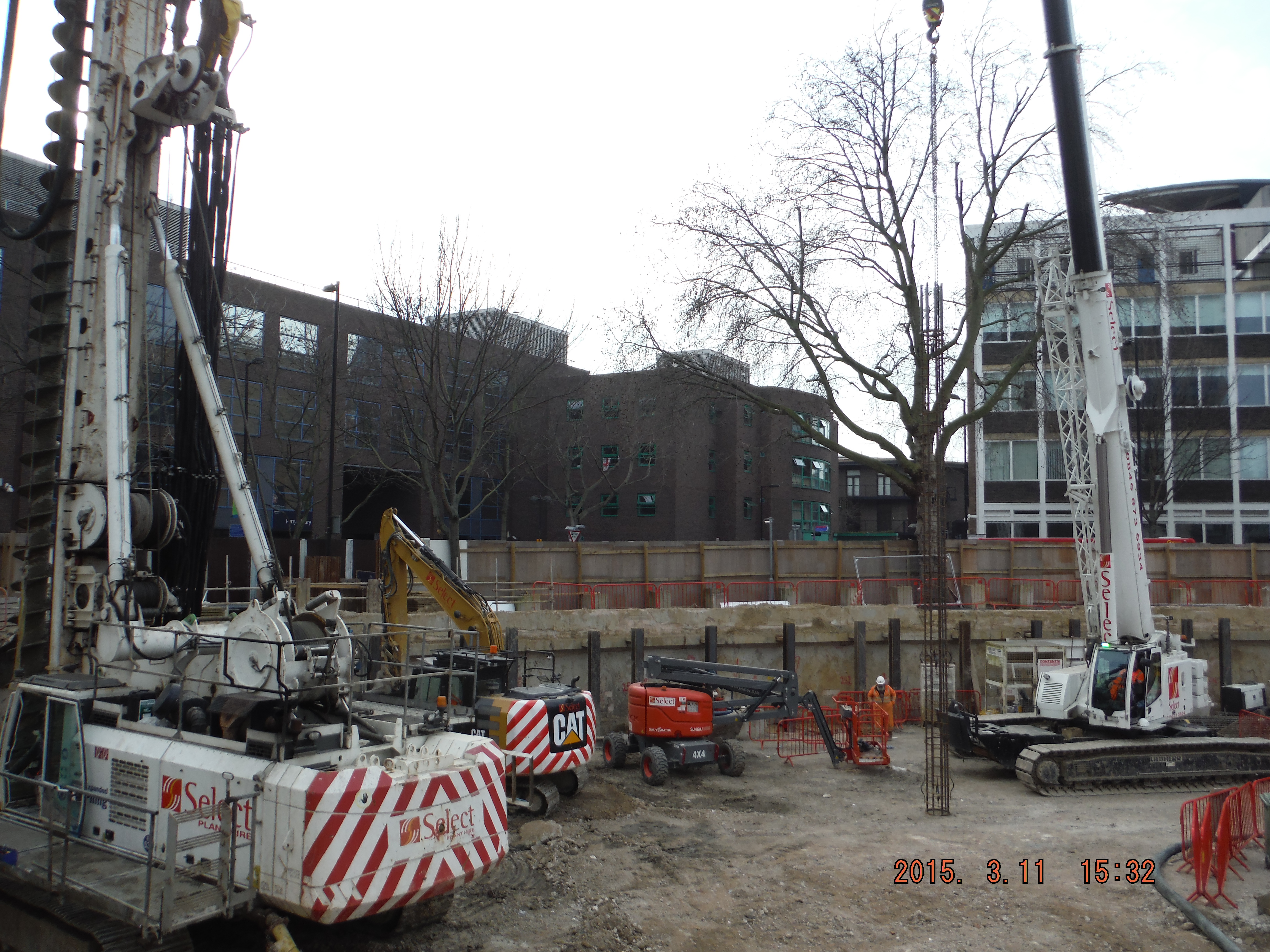
CFA. The first key point is that the space it needs is huge. Not just the longest drill bit you will have ever seen (it comes in 4 m lengths) but the guard which removes spoil from the auger means more space around it is needed. Additionally rather than just having a pile rig, crane (to lift reinforcement), and concrete wagons, you also need a pump which needs 3m of extension hoses, a thick hose line and an agitator (stationary concrete wagon) to mitigate typically infrequent concrete deliveries in London. Add this to the above Monday morning scenario and unless the situation is well planned you have problems. The first pile was constructed and the volume of concrete was horribly out requiring the pile to be drilled out and re-poured. Why – probably because the massive drill bit auger, without a casing, had brought in material from the edge of the hole making the hole much bigger. So what, well for a start, it is very difficult to predict the concrete quantity, secondly it makes for a very uneven pile and thirdly who pays for the extra concrete (about 30% extra than the cylindrical volume budgeted only, about 50% extra required)…
Crane moving reinforcement ready to be inserted into male pile.
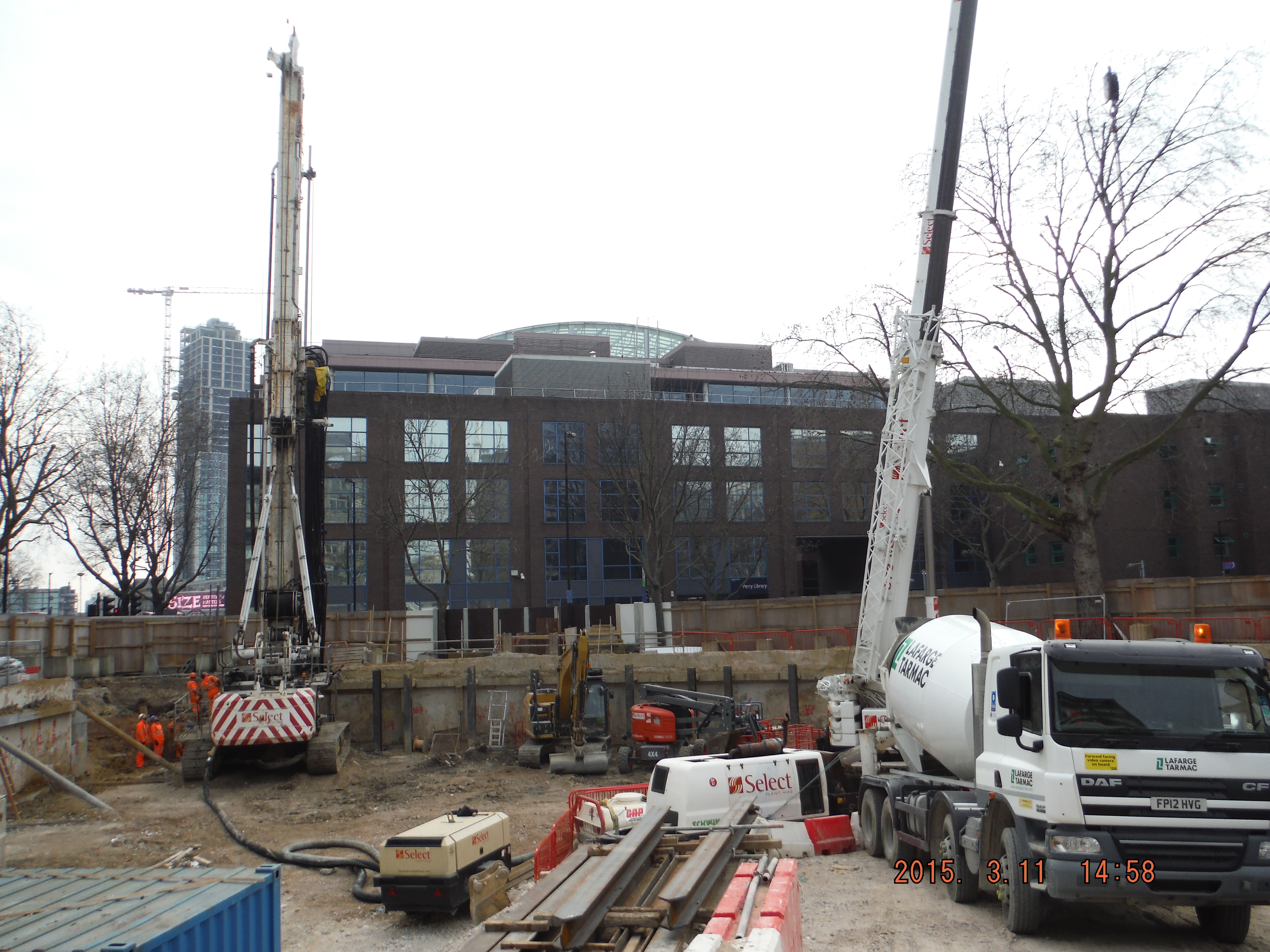
Alternative CFA concrete delivery – direct to pump without agitator.
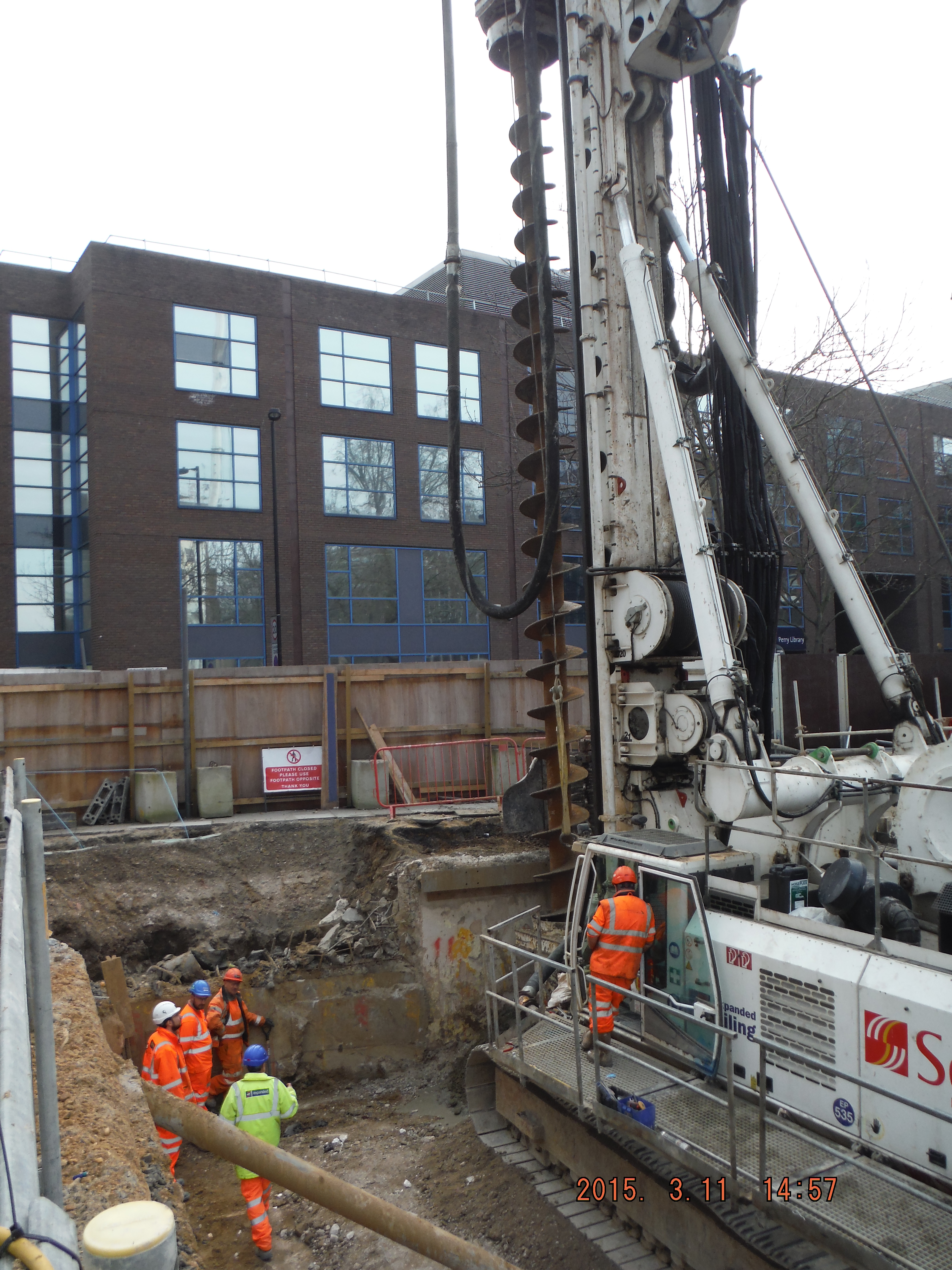
Auger guard hits back wall, solution – remove top of back wall!
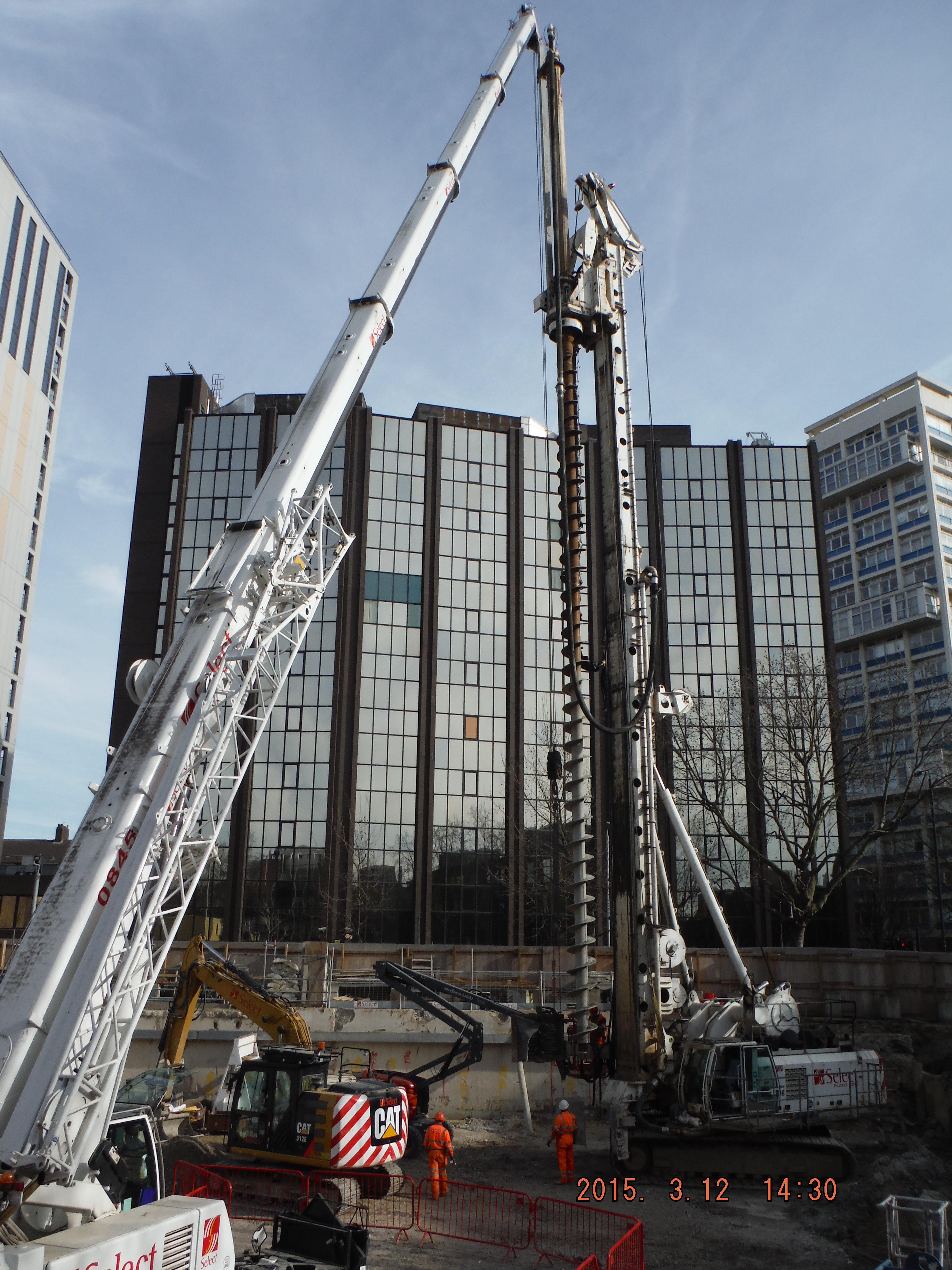
CFA – 30m auger
Expanse of CFA plant. Left: agitator (static concrete wagon), pump, hose, crane, (out of shot) pile rig.
UXO Survey. Some photographs of the magnetrometry in action (magnetometry or electromagnetic surveys are used in the search for buried UXO and rely on the detection of small variations in the Earth’s magnetic field caused by the presence of ferro-magnetic objects). The UXO survey was required as a result of a study of WWII maps highlighting a medium risk of UXO within a certain area within the site. Risk mitigation or contract covering exercise…
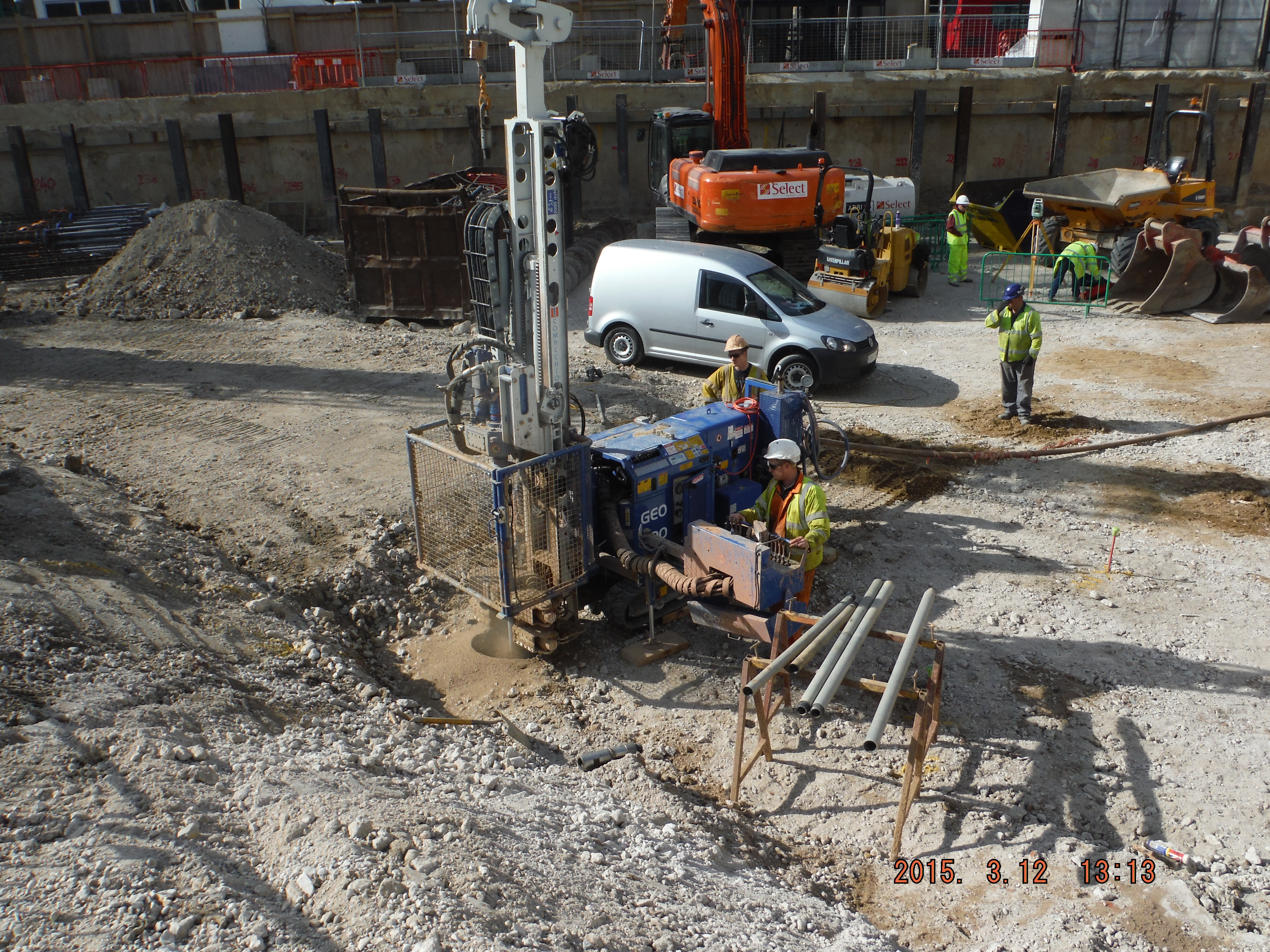
UXO probing: Drill, probe, analyse.
Note the compressed air causing the ground water to bubble in the previously dug holes (up to 9m away out of shot)

Like the reflection at 1. Intrigued by the removal of some of your retaining wall for access at 2. Is this causing any TW or reinstatement issues?
As a strongly irrelevant set of thoughts….I take it you found no UXO! What sort of radius does the compressed air installed probe allow you to investigate? Is it a case of installing ground probes and measuring between them or does it use resistance between the surface and a deep probe? BTW, How far below original ground level are you working? Wasn’t ground leve at least one storey above you and then excavated for the previous building? Was there really any need to look for UXO?
We had to look for UXO too, it was part of the planning application acceptance.
You were working from ground level down though weren’t you? This site had already been takne down bu a good 3m so unless there was something very large I struggle to believe it would have been down that deep and would have hoped it might have been found before.
Are you using a self compacting concrete or are you vibrating it somehow?
And I take it no bombs were found…?
Damian
The last photo is a good example of just how close the wording was to the excavation!!
Hi Richard. Thanks for the questions. Removal of retaining wall – I realise the picture was misleading. Previously the retaining wall was removed because of a concrete obstruction found when constructing the guide wall. On removal of it, it was found there was an old brick retaining wall (which must have been the method used to build the previous site) and so there have been no issues with the removal of what you can see. What I was actually referring to about the auger hitting the wall at the very top 400mm or so (you can just see the removed layer near to the guard next to the auger). This has not caused any issues as that is not much more than a paving slab thick and the underlying grout/soil/asphalt mix below it has not moved.
No UXO found. The compressed air is simply a way of enabling the probe to be lowered – it blows material out of the way to enable the probe to be lowered to about 5/6m depth – useful in the river terrace deposit Sand/Gravel which tends to fall in on itself. The radius of magnetic influence is about 2m from each hole (about 40 holes were needed in total to cover the area). The probe simply uses a magnetic field to detect any variations in the field (caused by ferrous metals – possibly bombs). Any big deflections in the magnetic field would be analysed further – in my case not required.
Regarding your point about needing to actually look for UXO. Completely agree – no need to do it at all – chances were very low. However, on the post WW2 bomb study maps there were a few hits measured close (15-20m away) and because the trajectory of a bomb is a “J” shape it was possible that there could have been penetration into the area of the new basement. We would be talking about a bomb being about at the basement level 2 floor level (about 7m below the original ground level) and so there was possibility of UXO if you combine a hit about 15m away striking at ground level. Unlikely, but enough for the exercise to be conducted – I supposed better to pre-empt than find through piling!
Guz – Yes – self compacting. Although the concrete in the rotary bored pile was mostly tremmie pipe filled to avoid segregation. The CFA piles receive concrete through the bottom of the auger as it is extracted and so it is under pretty high pressure (hence every void is filled) – I wonder if being under pressure reduces the air voids or not…
I’d say not to the last Q. Entrapped (not entrained) air forms bubbles which need to bee encouraged to rise out of the mix and it is a case of needing to overcome viscosity which would not be aided by being under pressure. Like Pete M’s Qs below and look forwards to response!
Good blog, I was just wondering what testing you’re doing on site for the mix going into the piles? I wasn’t directly involved with it on my site, but had sight of the numerous trial mixes (I used them for blinding after the tests had been completed – which had its own problems). Are you doing an L-box test? How often are tests taken and have you had to reject any loads yet? How far down the pile is the reinforcement cage? (i’m guessing there is a reinforcement cage?) And at what stage does the cage go in?
Hi Pete,
Thanks for the blog reply and questions – very useful to see what sort of things I should probably be asking myself!
Your questions deserve a more thorough reply than I will turnaround tonight – answers to follow on Wednesday (tomorrow is an “Ask the Question” H&S workshop).
Hi Pete,
On-site testing is simply a flow test to be at F5 (560-620mm) which is low consistence. This enables the concrete to be pumped and allows for 3-4hrs open period before curing. Last week we had 3 trucks of concrete for the CFA piles refused because the mix was too fluid (concrete ran off the table). I think that is the first instance of a refusal but probably at a good time to keep Tarmac Lafarge on their toes. Away from site the cubes are tested in a water tank at 7 and 28 days. All samples so far have easily reached the design strength of 30/37N/mm2 (for the secant wall). In terms of number of samples we conduct a flow test for every wagon and take a set of cubes per 50m3 (about every 4 piles). No L box tests are conducted – I understand this is a consistence test developed by the Australians. Have you heard of this being used in addition to a slump/flow test?
Regarding mix design, it seems by specifying the use for piling (and pumping) there is no requirement for any form of vibration, mainly because the concrete is self compacting and would not be practical to vibrate a 28m long cylinder.
The specification determines the constraints:
Cement Type CIIIA+SR
Maximum Aggregate Size (mm) 20
Target Slump (mm) F5
Minimum Cement Content 320
Max Water / Cement Ratio 0.55
Chloride Class 0.40
Exposure Class DC-2
Which translates to the following mix design for the CFA 32/40N/mm2 piles:
Cement:
Portland Cement (CEM I_52,5N) – 200kg/m3
REGEN (GGBS_EN 15167) – 200kg/m3 (GGBS gives sulphate resistance)
Aggregate:
4/10mm Single Size Gravel – 296kg/m3
10/20mm Single Size Gravel – 691kg/m3
0/4mm Concrete Sand MP – 749kg/m3
Additives
ChrysoFluid Optima 100 – 2.64kg/m3 (looking at the data sheet – this is a plasticizer – water reducer, used for the pumping of concrete over long distances)
ChrysoFluid Optima 206 – 0.88kg/m3 (this is used to create a high water reduction and/or an increased period of workability retention. It produces concrete with a long workability retention without prejudicial set retarding effect.)
Water – 171kg/m3
Aggregate/ Cement Ratio – 4.34
Water/ Cement Ratio – 0.43
Percentage Fines – 43.15
In terms of the CFA process for the secant pile wall, step one is to drill the hole, two: 2 pump concrete through the auger to the pile base and then three: retrieve the auger by pulling it up the same rotation way it went in at a rate to maintain pressure in the concrete. The auger is then moved out of the way and the cage inserted. To sit the cage at the correct height it is sometimes seated on legs with flat ends. Due to the generally low consistence mix there have been no problems inserting the reinforcement.
However, for the ground bearing piles where they are going to be installed at the first basement level, and then we will excavate around them to basement level 2, the reinforcement will be installed using an RSJ to push the cage to the specified depth and then the RSJ will be recovered. A 10mm rope will be fixed to the cage lifting ring and tied off to a 32mm bar sitting across the top of the pile to stop the cage sinking further. Buoyancy of the cage is not an issue based on mass of reinforcement cage. This will avoid having to break the piles down with reinforcement in (avoiding the Mr Cropper stories of blogs gone by, I hope!).
I suspect, going back to the concrete mix design/testing (let alone the plans to produce waterproof concrete in certain areas), there is a TMR in there somewhere… (Richard?)