Archive
Condors, Piling Methods and Bomb Hunting
Site Two Fifty One
I’ll reflect on 3 points this week.
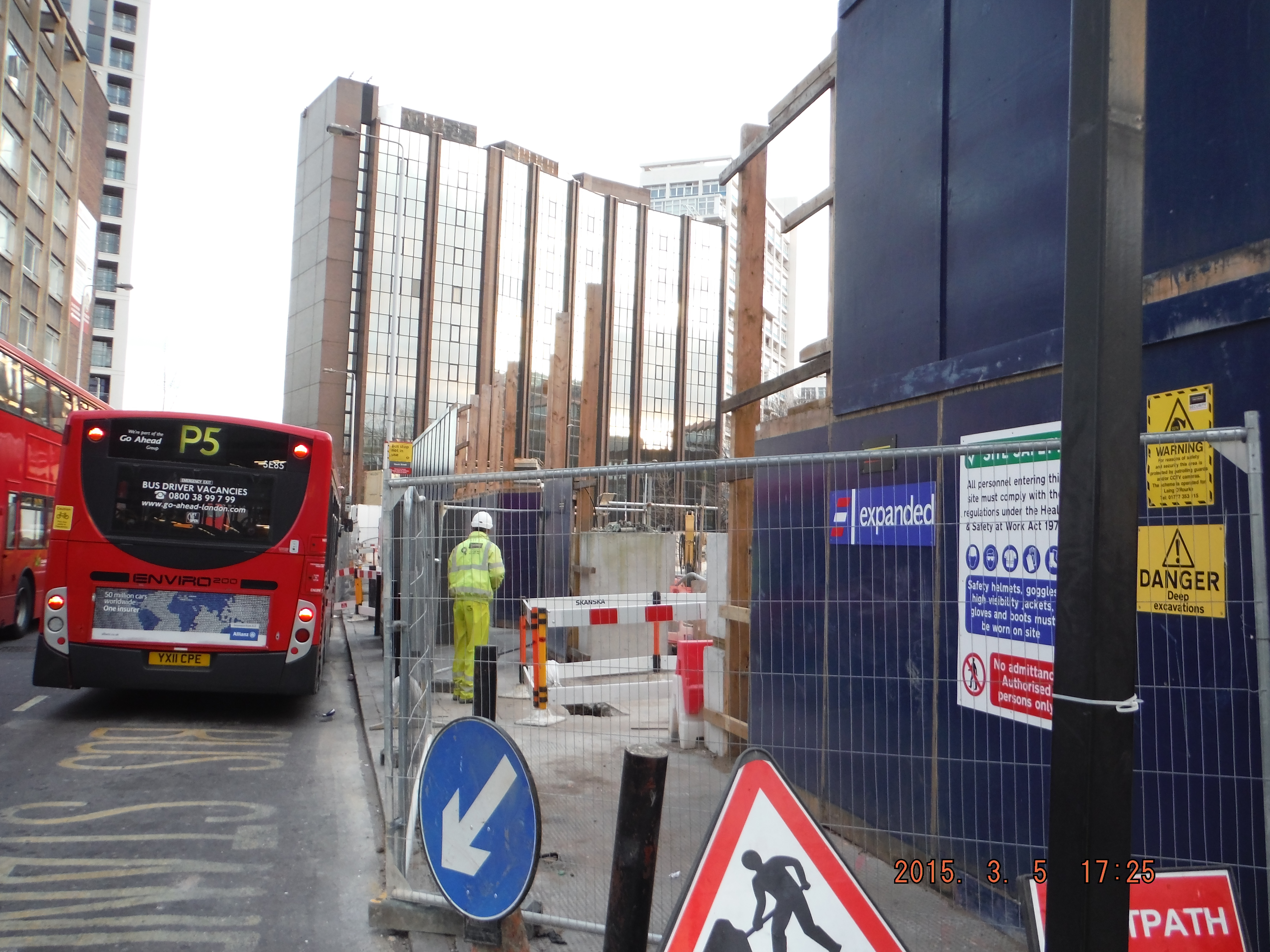
1. Sensible Health and Safety. This week’s Monday morning was more “Monday morning” like than any other – the busiest day on and around site to date. PM on leave and Project Engineer arrives at 9.30am (site works start at 0800). Typically muck away lorries, UXO survey team, slab breaking, pile rig conversion (rotary to CFA), perimeter hoarding move, substation re-routing and traffic management all collided at once. Add in the client’s representative visiting and an already confined and cluttered space and you have issues. Unfortunately the UXO survey team arrived late, muck away trucks got stuck and converting a pile rig needs loads and loads of space. This inevitably started to cause chaos and not just the site was becoming unmanageable, the roads around the site perimeter were getting blocked. This was the time to take the condor moment: step back, think and act. I chose not to and felt the client’s representative needed to be briefed. I missed the increasing hazards and did not take control. Shortly arrived the Project Engineer arrived he stopped the works (not for long because it just needed a few composed minutes to sort things out), cancelled further muck away, and installed new walkways to make safe passages between work areas. Simple stuff and a big lesson learned for me to then reapply the following day when the situation changed again.
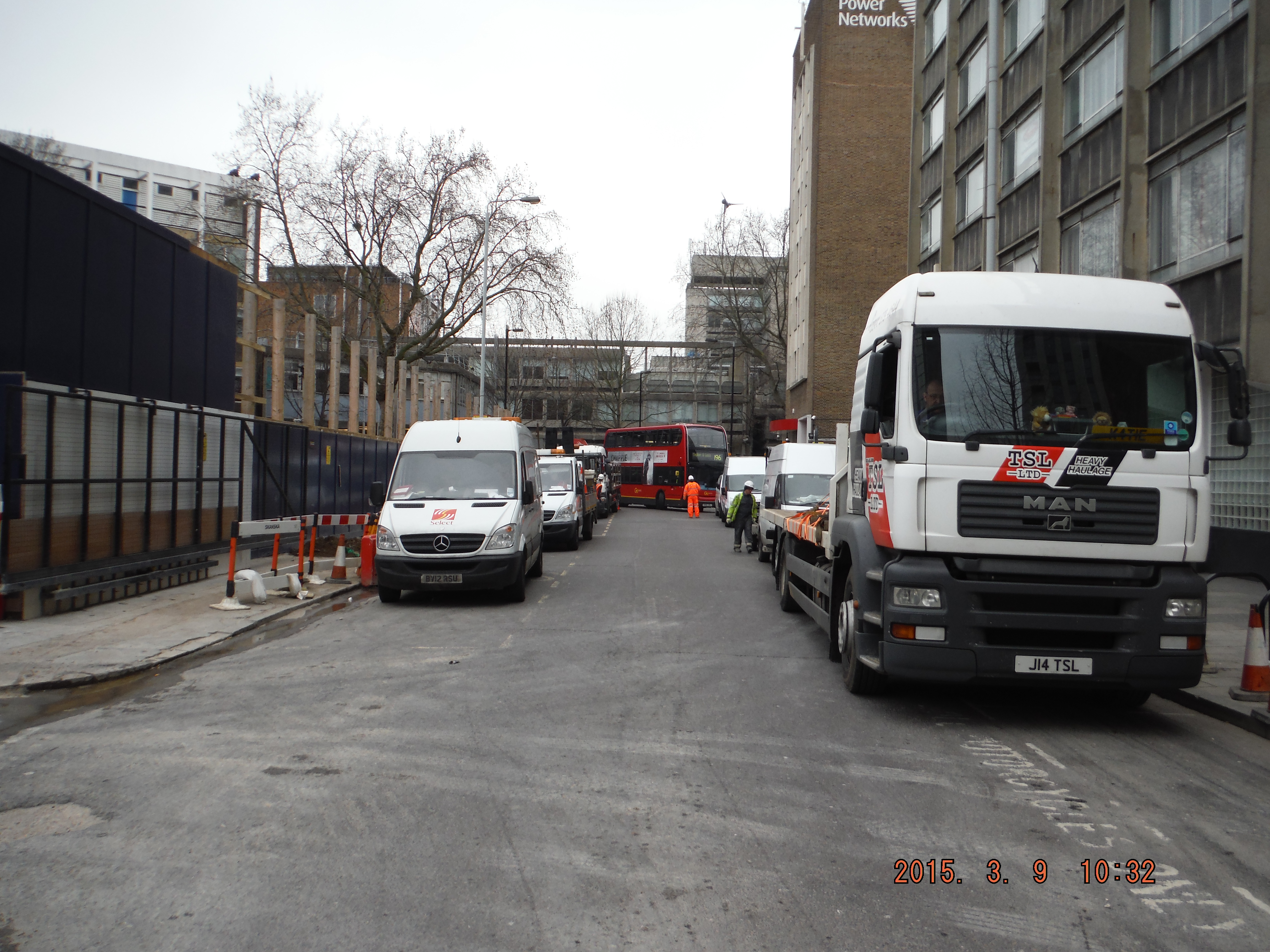
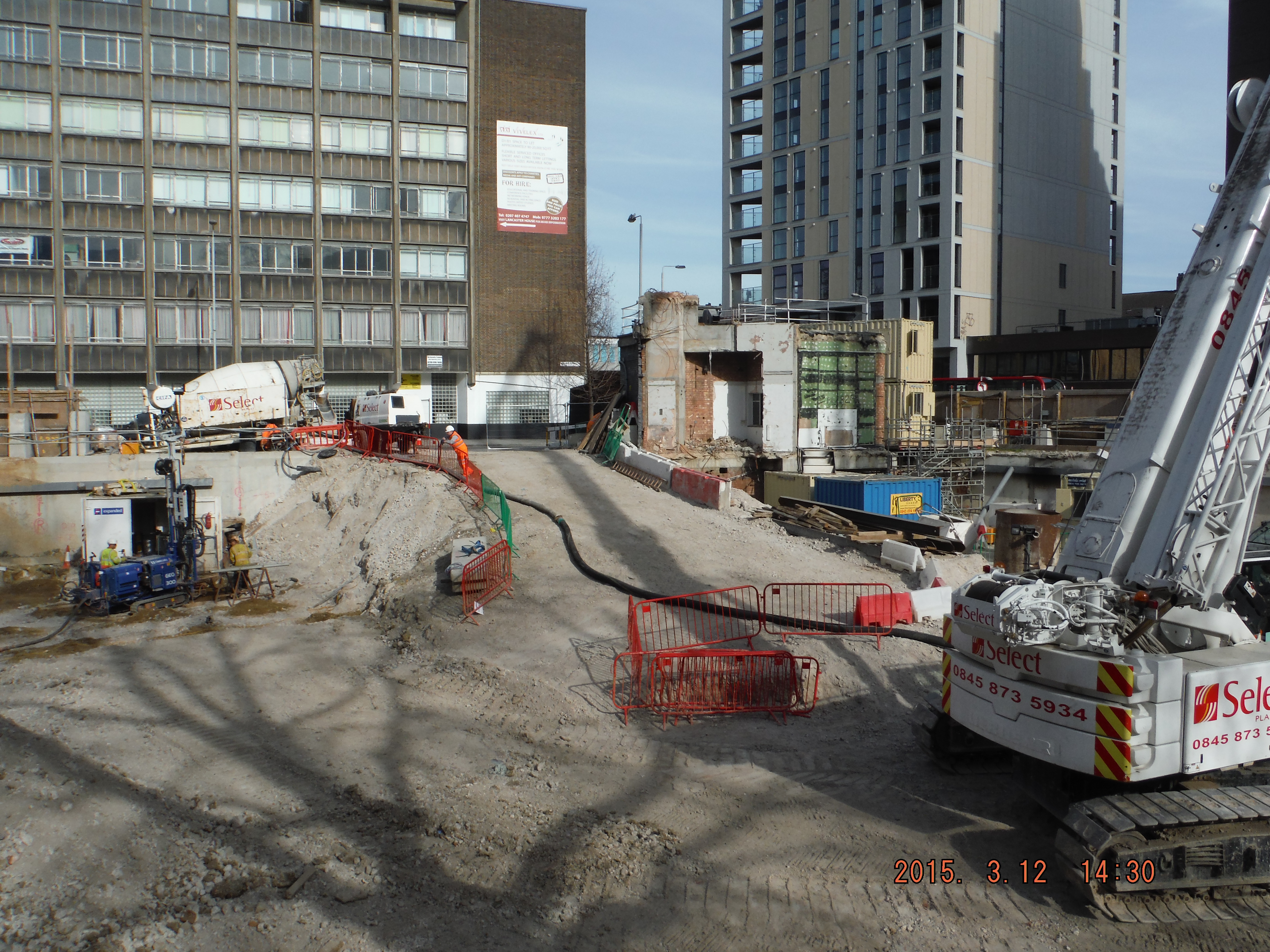
Site perimeter, Gaunt Street, choked with site vehicles. See high-ab arm at the back and the London bus attempting to get through.
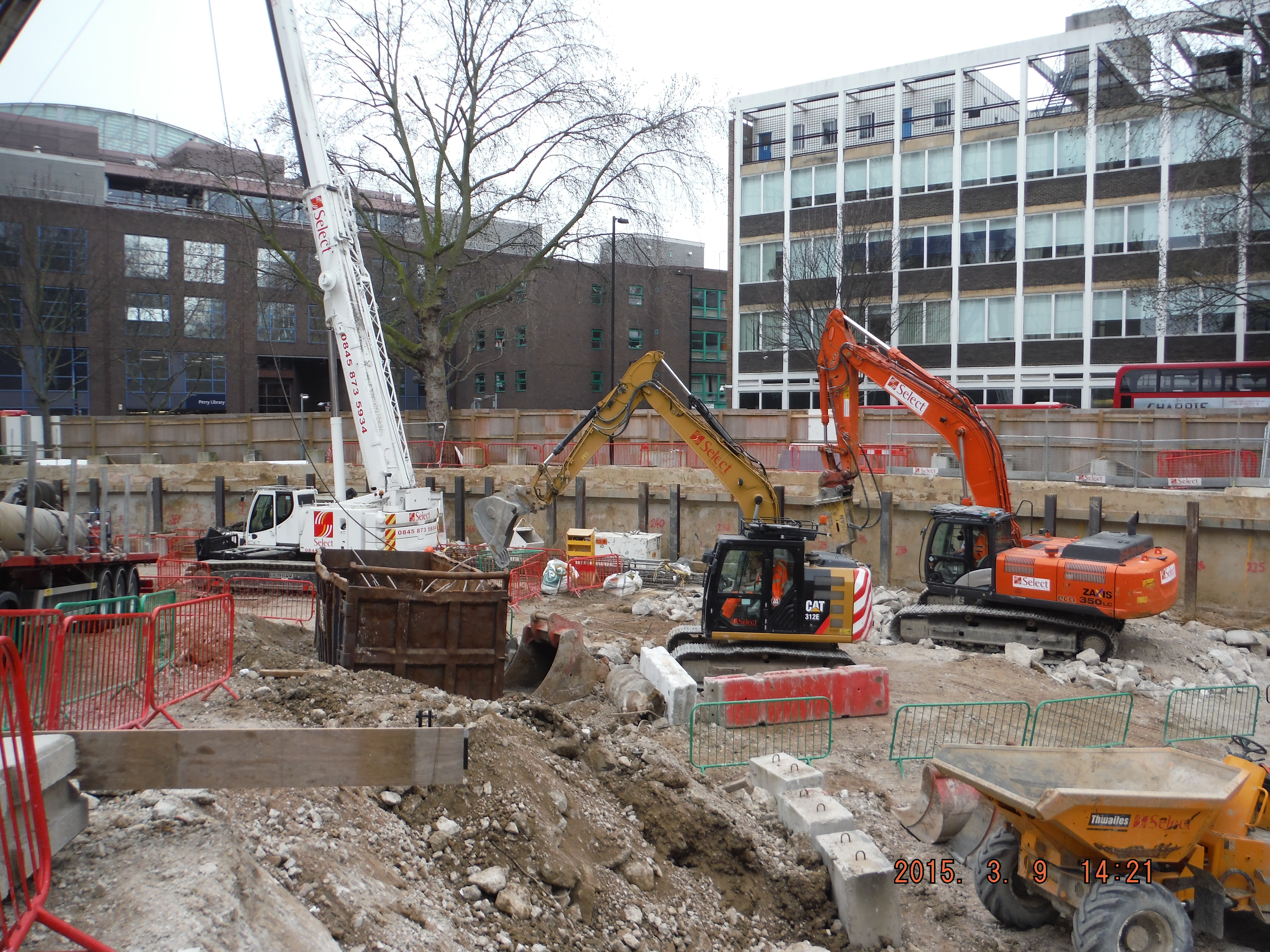
Site in overflow: slab breaking, excavation, skip exchange, deliveries, piling and UXO.
2. Pile type, Rotary to CFA. Some reminders for me/anyone who is doing either type of piling in the future. Firstly, allow 3-4 days, not 1 or 2.
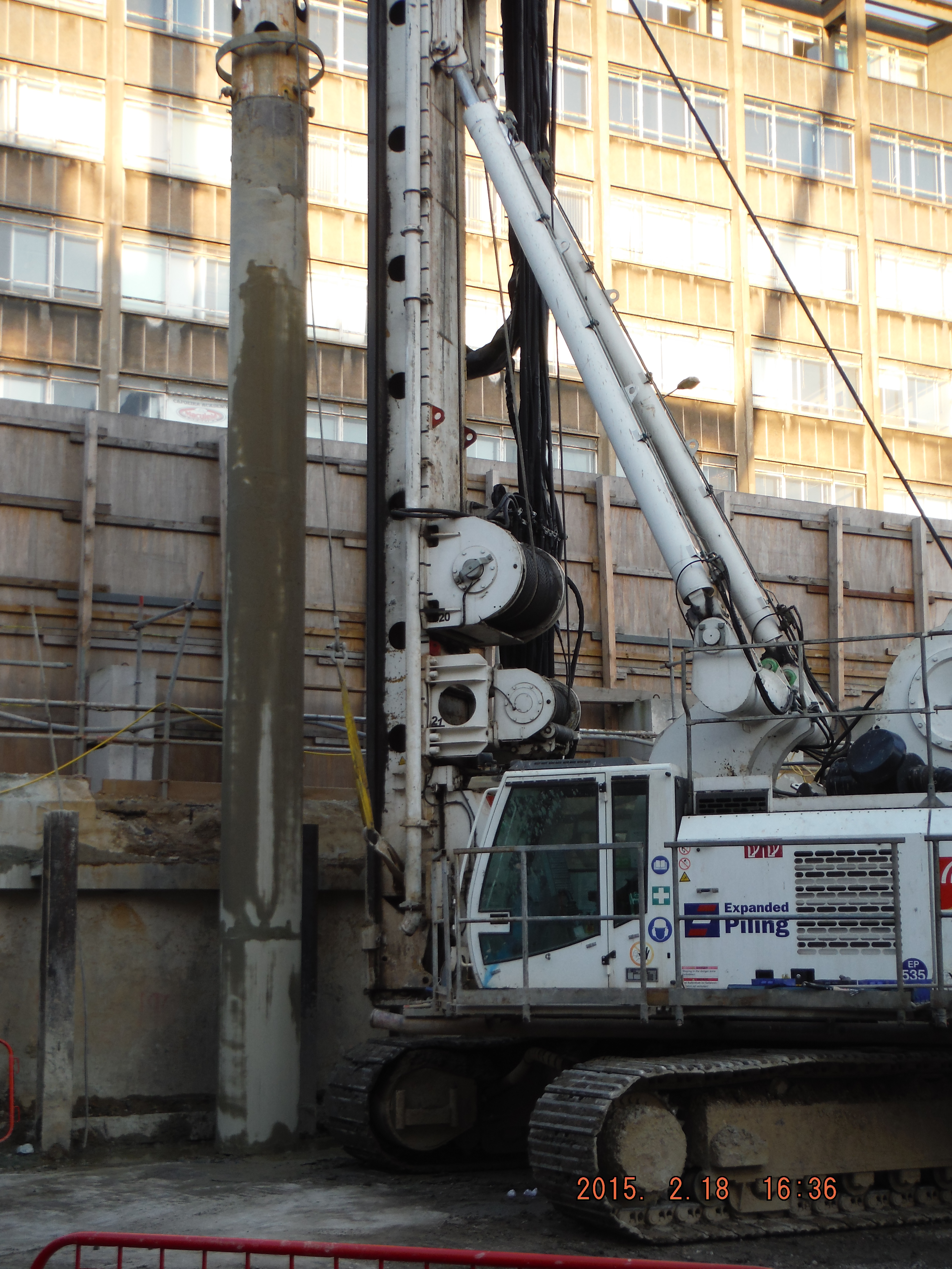
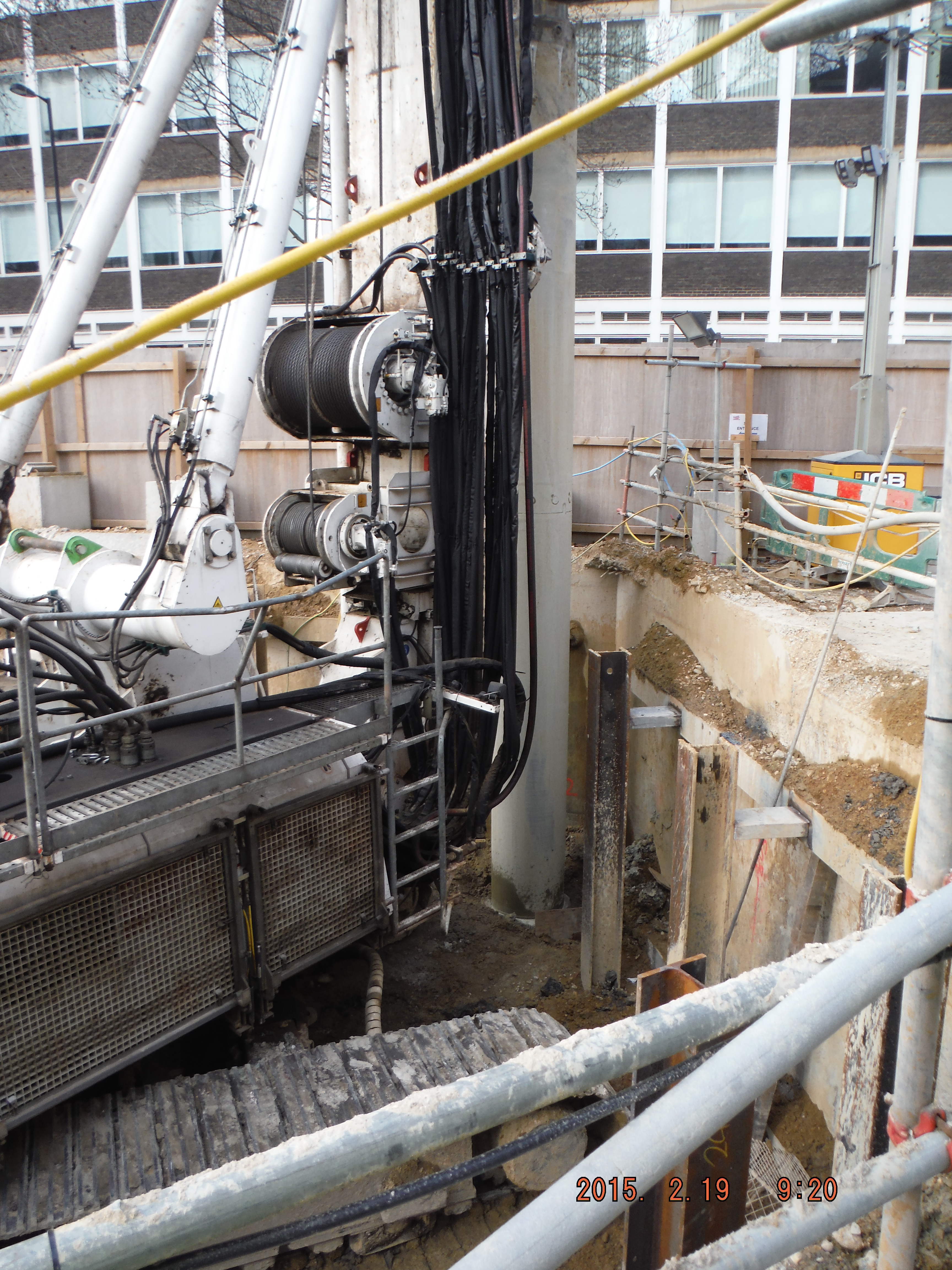
Rotary bored (replacement). This is where the casing is bored into ground and a rotating auger is used to excavate the soil within. Casing keeps the hole open and makes a pretty neat pile. This method struggles to work at 38m depth and in dense sand – hence the change to CFA.
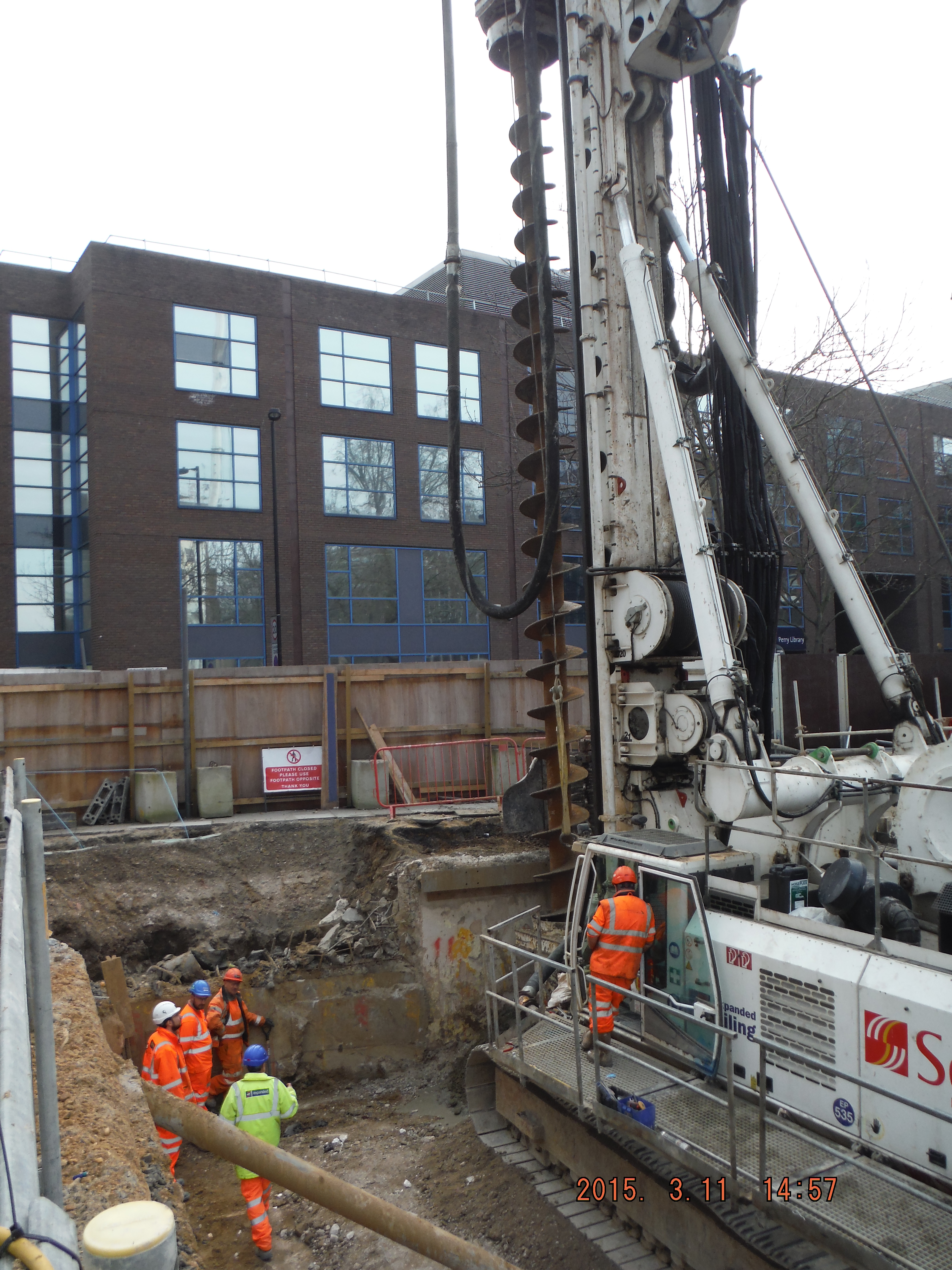
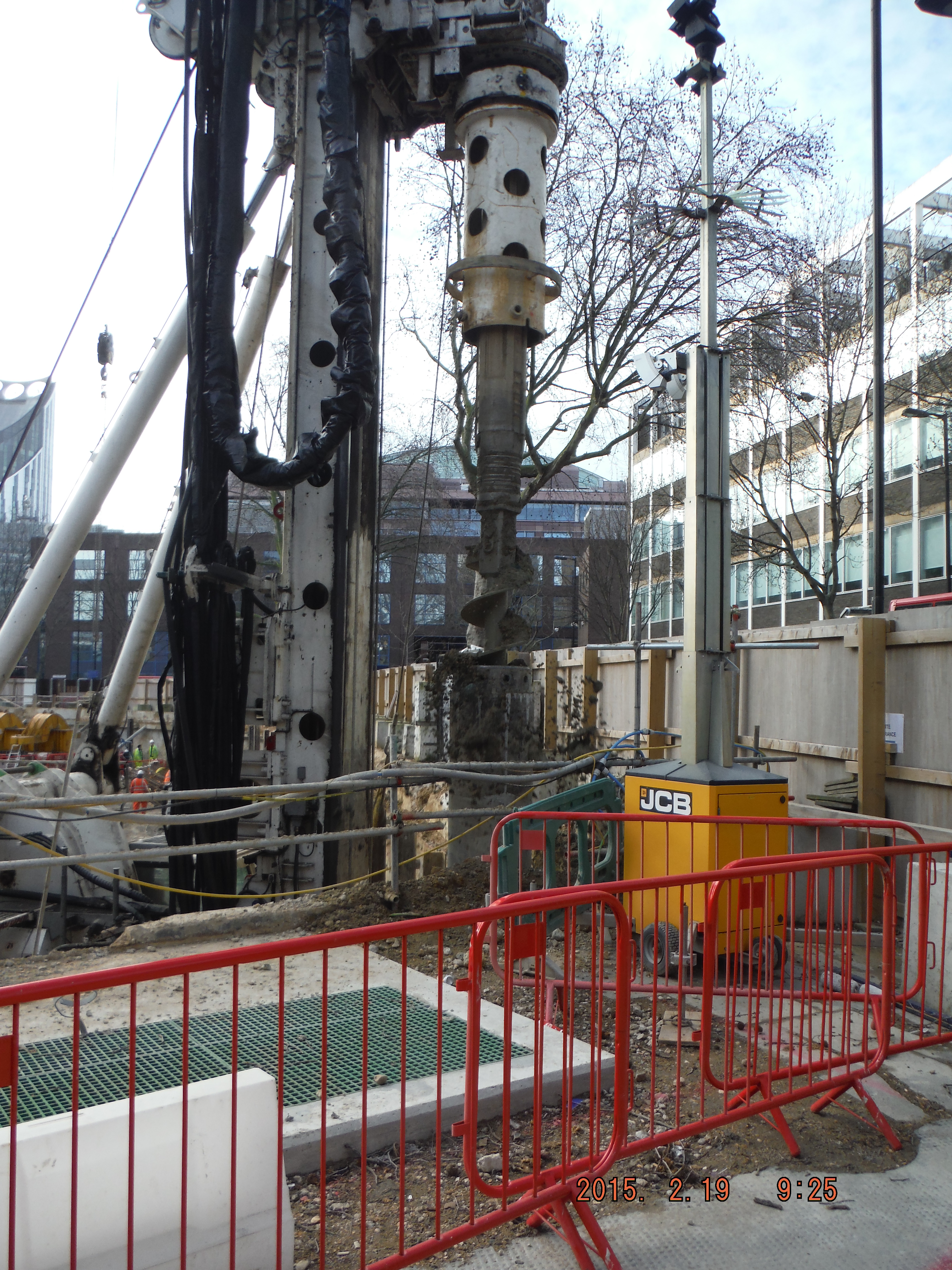
CFA. The first key point is that the space it needs is huge. Not just the longest drill bit you will have ever seen (it comes in 4 m lengths) but the guard which removes spoil from the auger means more space around it is needed. Additionally rather than just having a pile rig, crane (to lift reinforcement), and concrete wagons, you also need a pump which needs 3m of extension hoses, a thick hose line and an agitator (stationary concrete wagon) to mitigate typically infrequent concrete deliveries in London. Add this to the above Monday morning scenario and unless the situation is well planned you have problems. The first pile was constructed and the volume of concrete was horribly out requiring the pile to be drilled out and re-poured. Why – probably because the massive drill bit auger, without a casing, had brought in material from the edge of the hole making the hole much bigger. So what, well for a start, it is very difficult to predict the concrete quantity, secondly it makes for a very uneven pile and thirdly who pays for the extra concrete (about 30% extra than the cylindrical volume budgeted only, about 50% extra required)…
Crane moving reinforcement ready to be inserted into male pile.
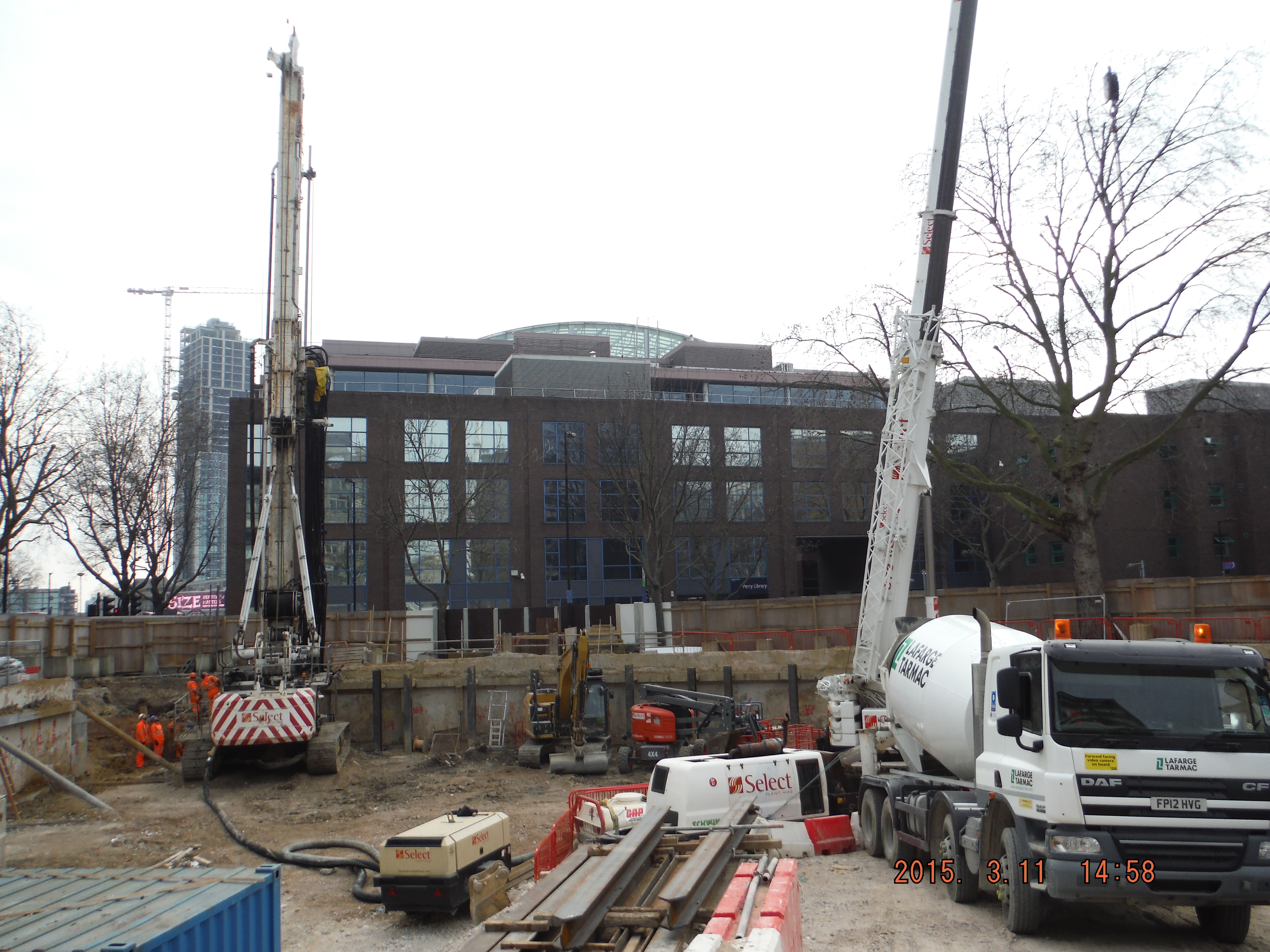
Alternative CFA concrete delivery – direct to pump without agitator.
Auger guard hits back wall, solution – remove top of back wall!
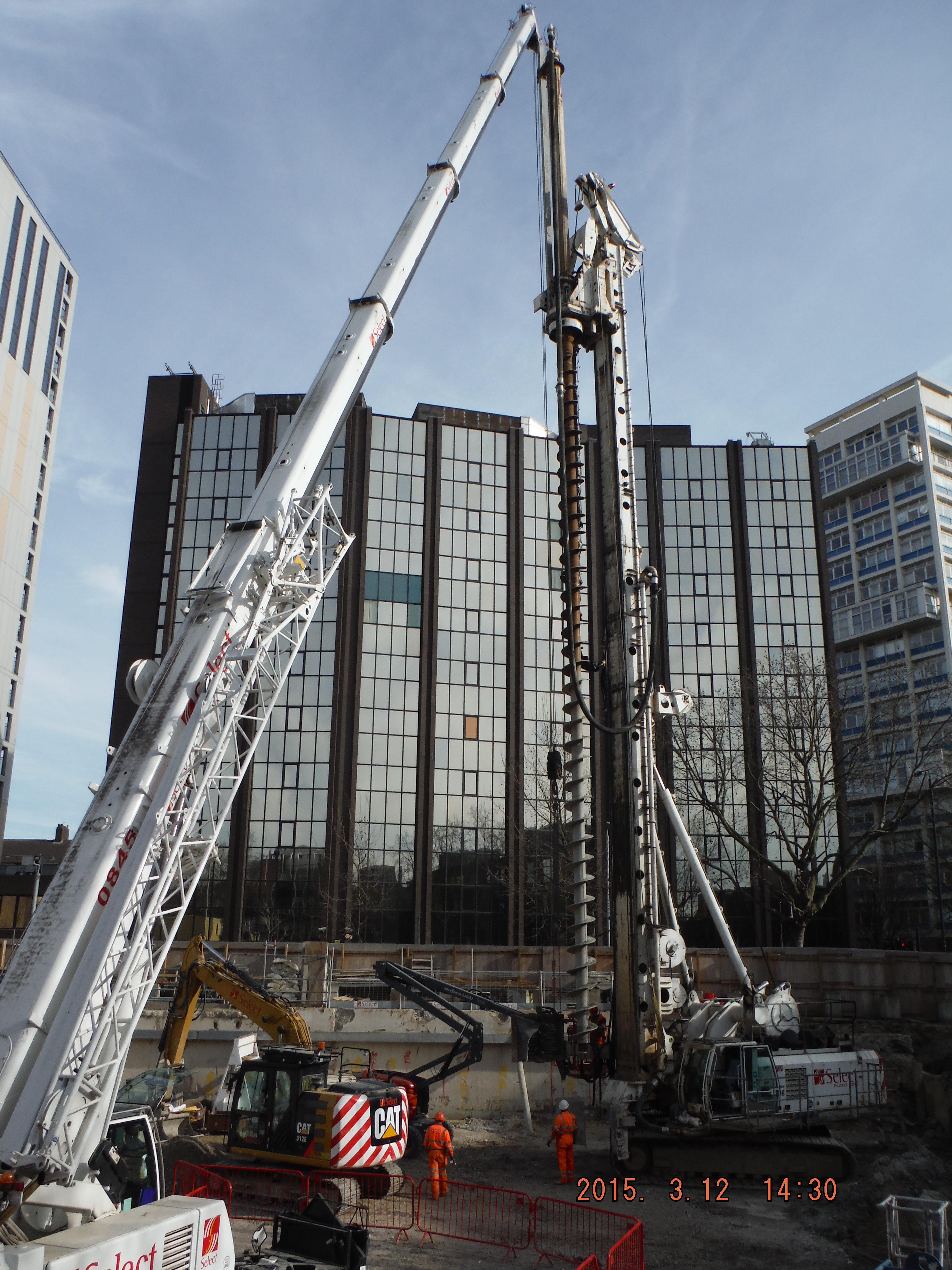
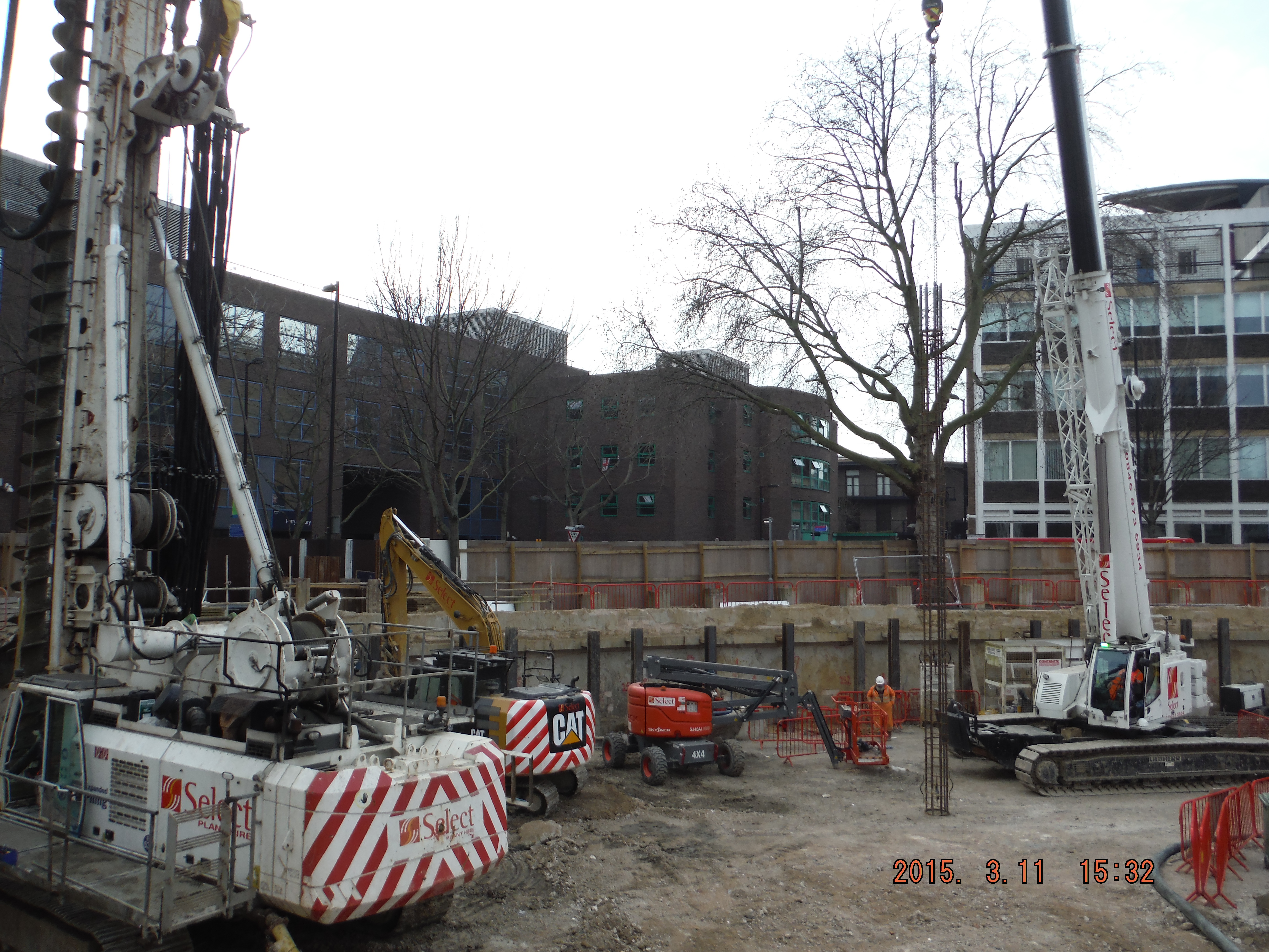
CFA – 30m auger
Expanse of CFA plant. Left: agitator (static concrete wagon), pump, hose, crane, (out of shot) pile rig.
UXO Survey. Some photographs of the magnetrometry in action (magnetometry or electromagnetic surveys are used in the search for buried UXO and rely on the detection of small variations in the Earth’s magnetic field caused by the presence of ferro-magnetic objects). The UXO survey was required as a result of a study of WWII maps highlighting a medium risk of UXO within a certain area within the site. Risk mitigation or contract covering exercise…
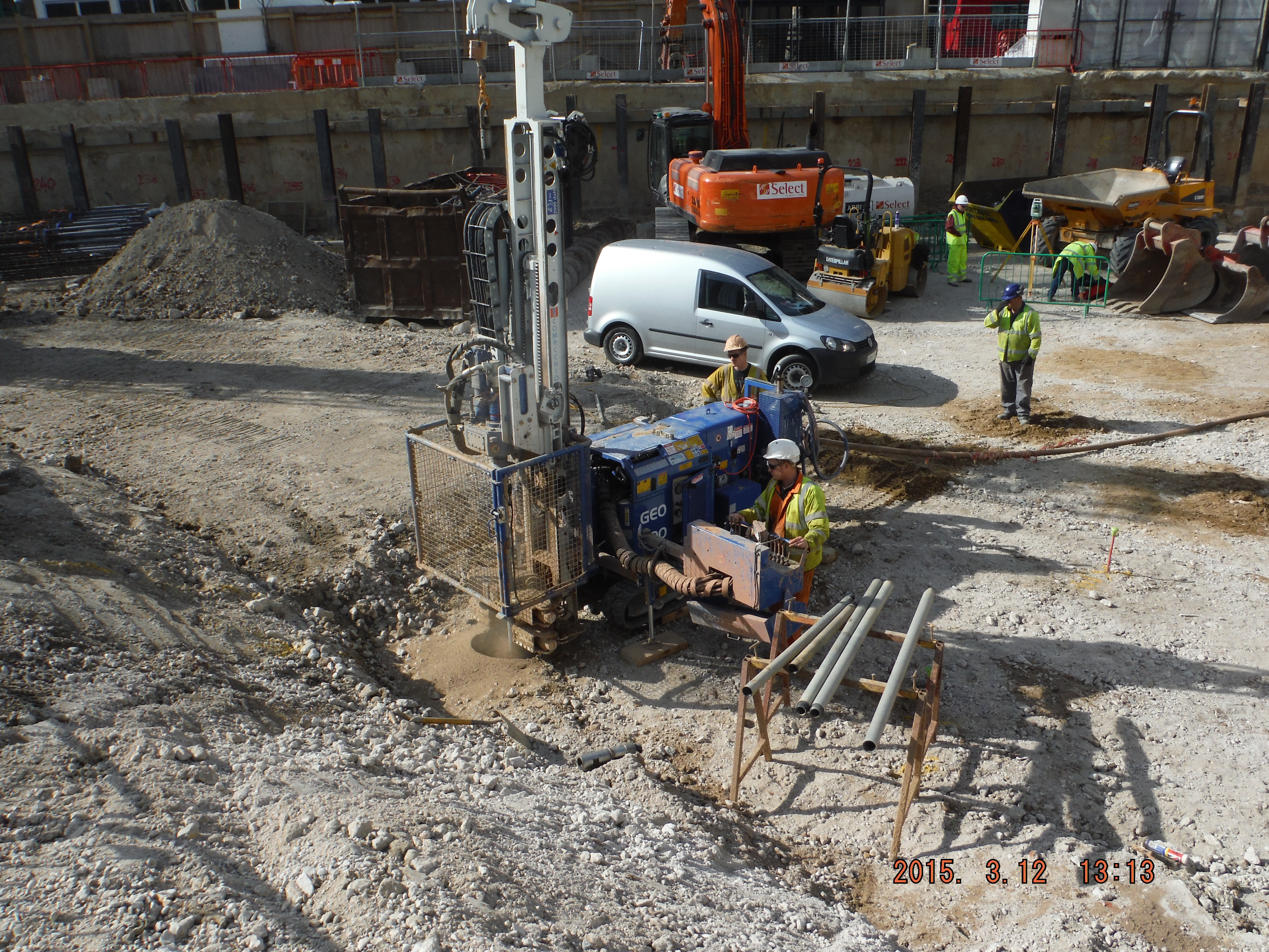
UXO probing: Drill, probe, analyse.
Note the compressed air causing the ground water to bubble in the previously dug holes (up to 9m away out of shot)
Underpinning, Tea & Railings
It has been a busy and interesting couple of months with Michael Barclay Partnership in London. I’ve committed a couple of weeks to learning AutoDesk’s structural modelling software, Robot, amongst other design work. It has been somewhat frustrating to get the hang of, since the slightest fault in the model can cause the model to terminate the analysis. This means you need to de-construct the model to find the fault. This can be exceptionally wasteful of time. The software also crashes inexplicably so you can lose a lot of work if you don’t save regularly!
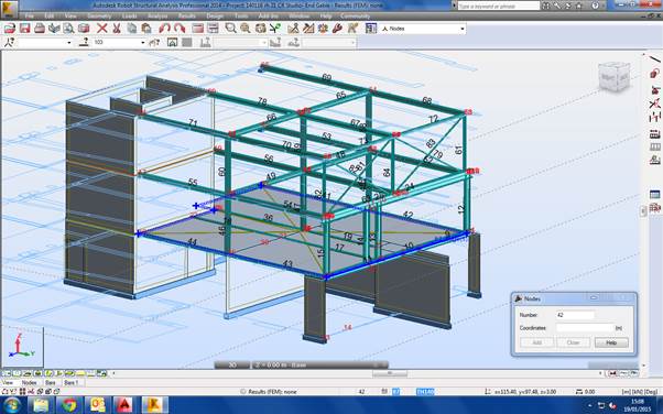
Modelling Cabul Road
The key principles when modelling with Robot are therefore to:
- simplify your structure as far as possible
- only model what you need
- verify and mesh the structure as you go
- know what results you need and what they should look like
- save regularly
Progress on the Cabul Road redevelopment project is ongoing, but somewhat slow. Planning permission is still outstanding and it is likely now that changes to the massing of some units will be required. I have completed a prelim structural scheme, outline demolition drawings, temporary works design to retain a terraced gable wall that will be exposed with the demolition of 4 properties. I’ve also designed the two new large roof structures in structural steel. The project also requires significant underpinning to the existing structure and party walls. I have had to research and learn about the Party Wall Act and what the responsibilities of the developer are. I also understand about Demolition Notices and the Planning Procedure. Other interesting points on this project has been to determine the disproportionate collapse class (the fifth floor of the flats is less than 50% of the total area), basement waterproofing strategy, positioning of movement joints and structural floor choice.
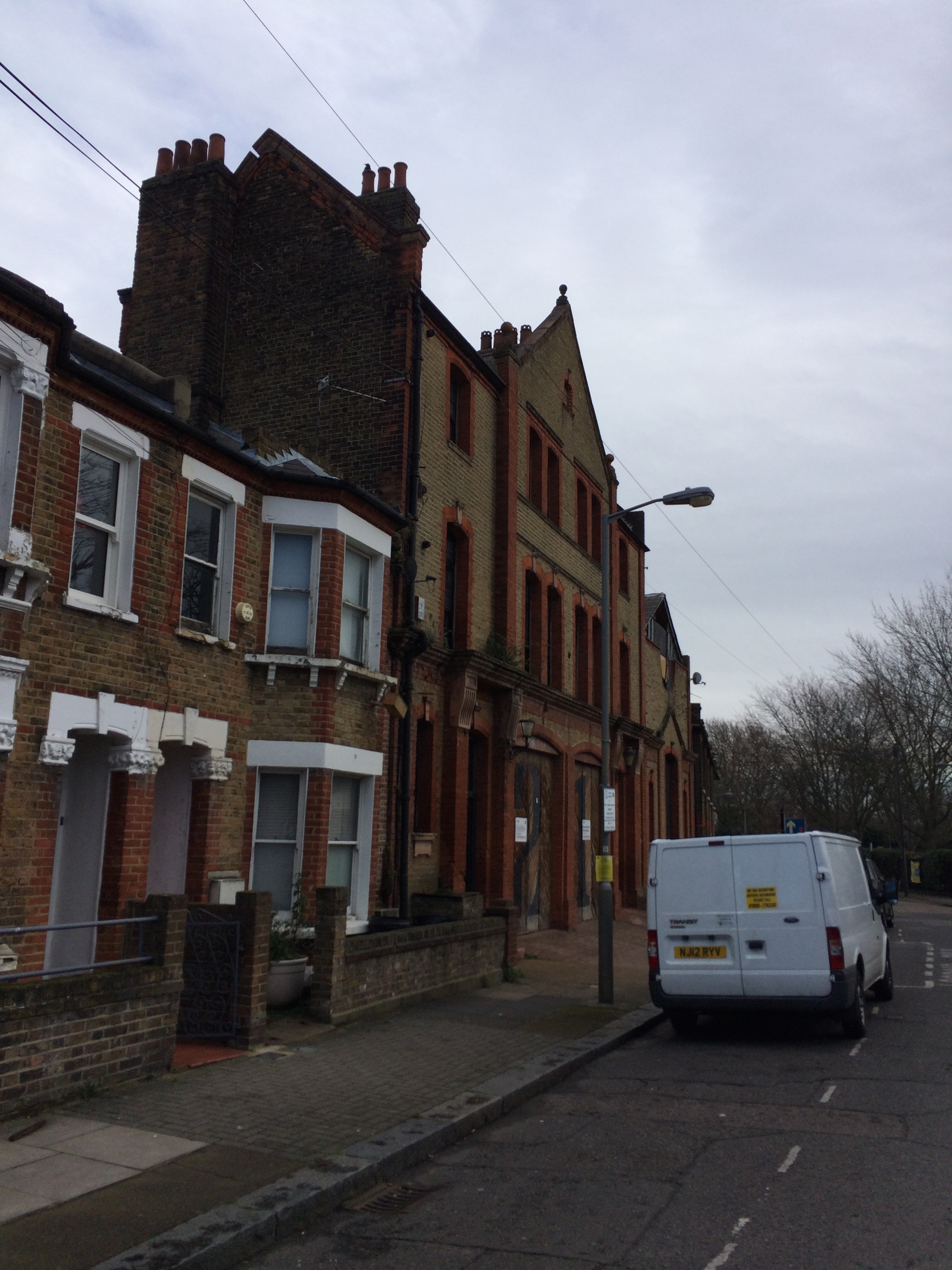
21 Cabul Road
I have also been involved in some other projects. One of these is Albion House, in Woking. It is a disastrously ugly and unsightly 9 floor tower next to the train station. The client’s aspiration is to redevelop the tower and maximise net lettable space, either by removing one of two stairwells, or placing another storey on the roof. The advice that I have been able to provide with MBP is shaping how the clients are costing the alternative business cases. More work is to follow on this one.
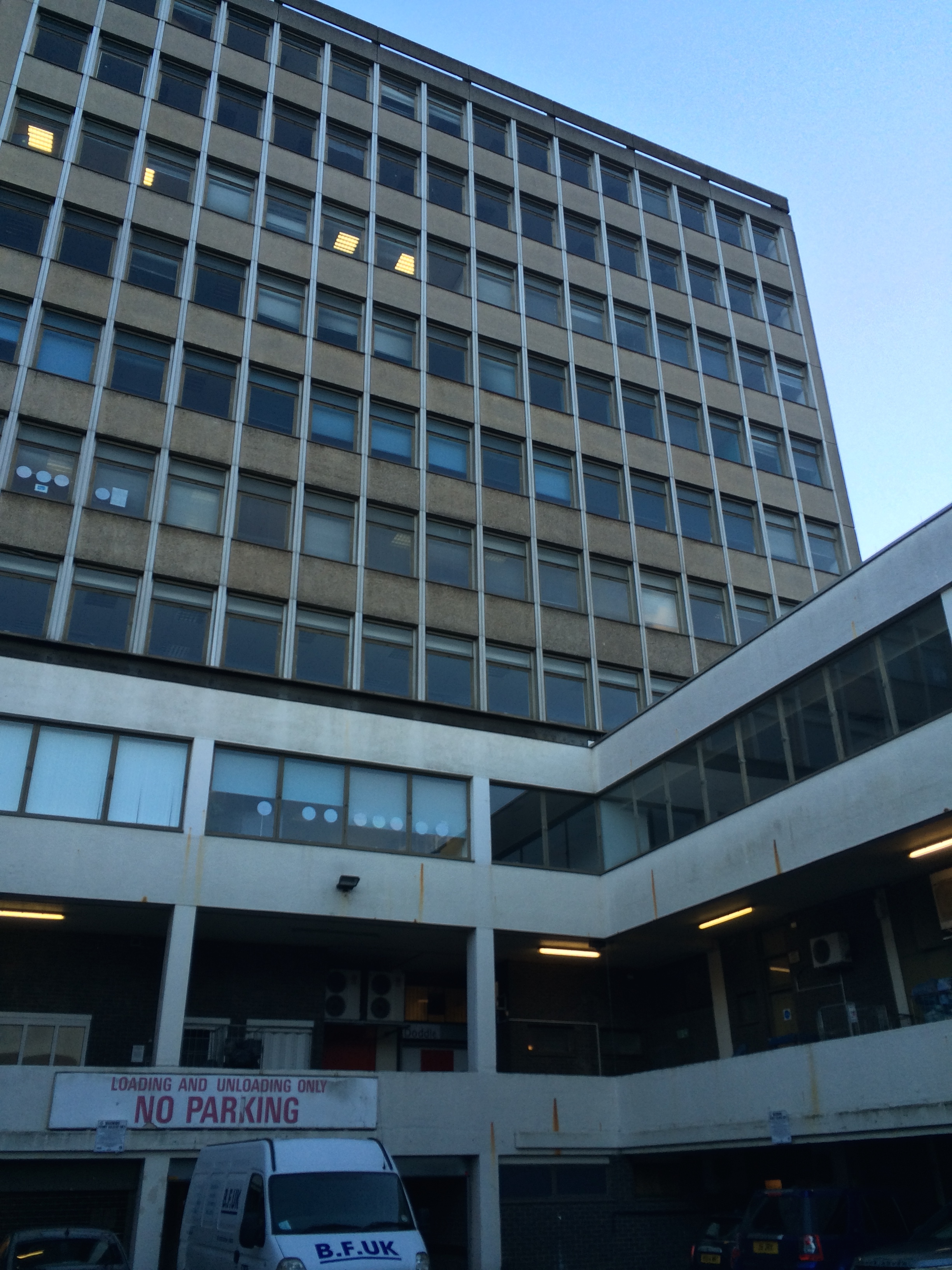
Albion House, Woking
Michael Barclay Partnership support UCL and I’ve become involved in a mentoring scheme. As part of this I am mentoring a 4th year Masters student who is undertaking their design project. It has so far been an interesting and enlightening experience into mentoring.
In other news, I managed to pour a whole mug of hot tea into my lap whilst in a client meeting last Monday. I then had to spend the next 15 minutes drying my trousers under a hand dryer in the loos! And to cap it off when I ran home on Thursday I tripped and impaled my right hand on some spiked railings! I then spent three hours in A&E and the whole of Friday getting surgery. I’m now sat at home with my hand stitched and bandaged like a boxer!
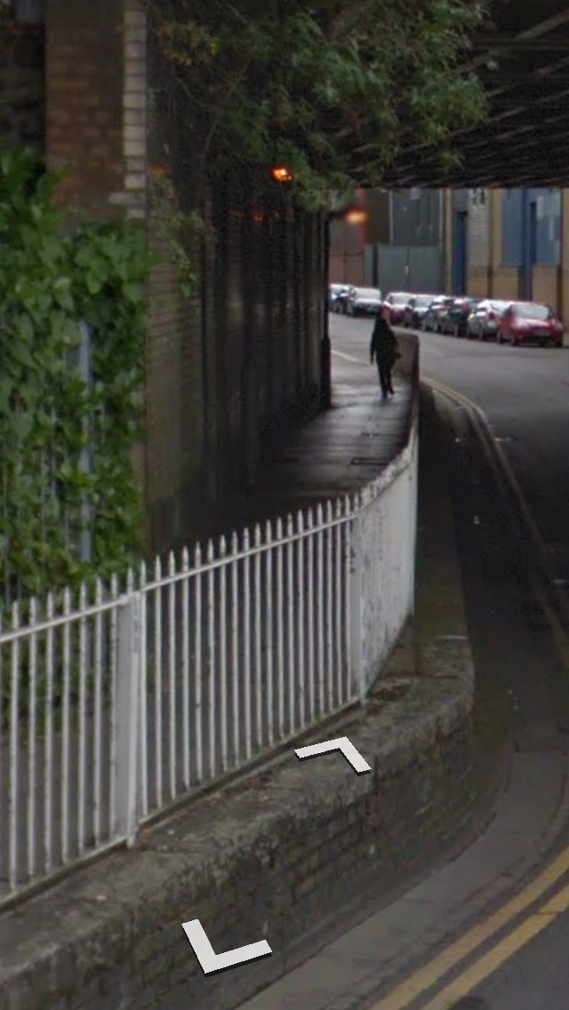
Here are the railings.
The question is, why are there spikes on a guardrail at hand level? It is all rather inexplicable to me! To frustrate me more, having paid PAX personal injury insurance for years since my wound wasn’t from a knife, blast or bullet I don’t get bugger all from them!!! Thanks.

I hope your week was better than mine!
It’s a hole new world out there.
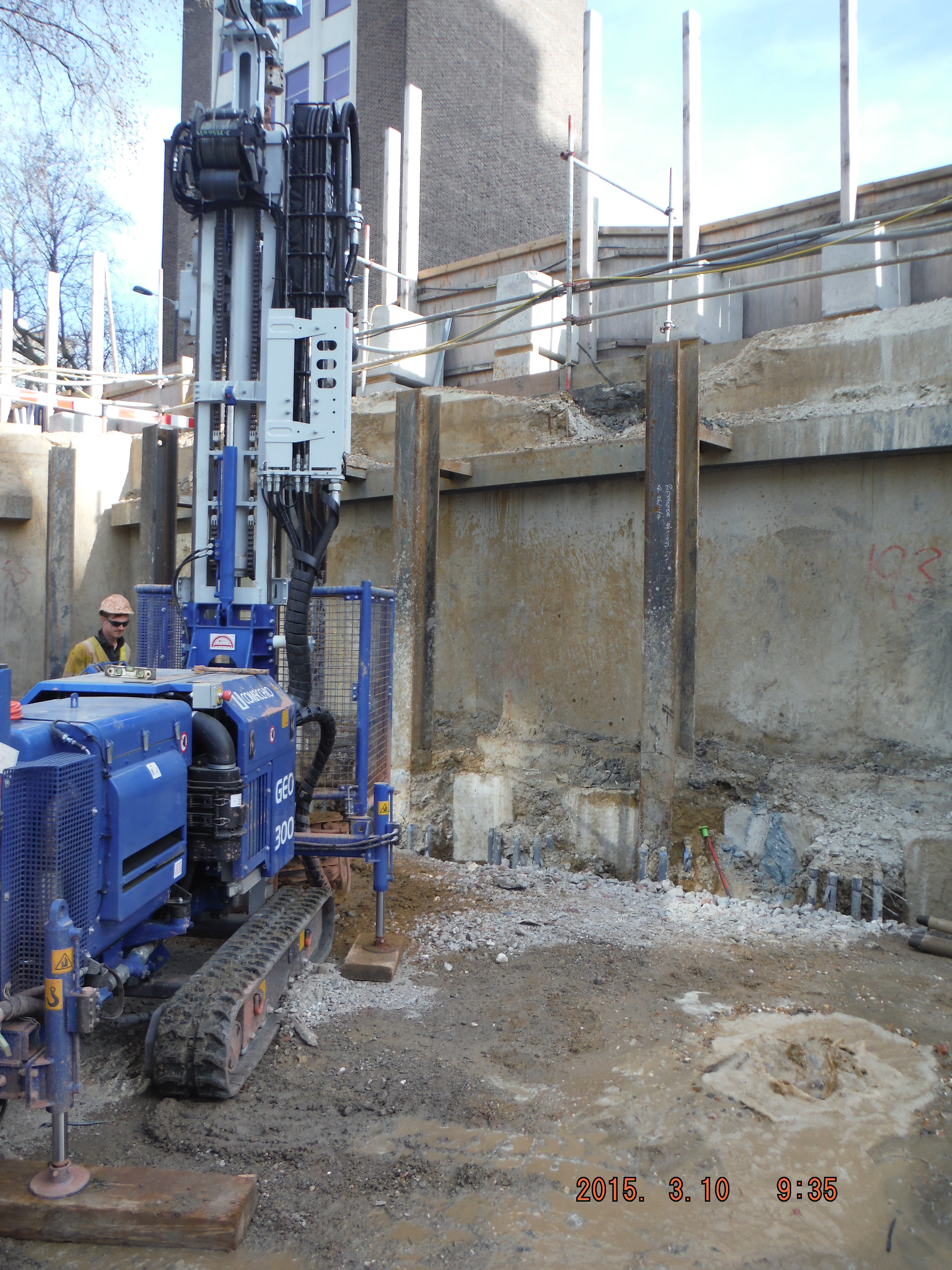
Site Two Fifty One
The aim of this blog is twofold. One – highlight what I am doing and learning on site, and two, discuss unforeseen ground conditions.
I arrived on site on 16 Feb and since then the focus has been on constructing the secant pile wall. The pre-existing site had one level of basement with an 800mm slab acting as the bottom prop. The slab is being used as the edge of the guidewall for the secant pile wall construction. The male piles, installed at the first basement level, extend to 26m depth through 6m of river terrace deposits and then into London Clay acting as an impervious cut off. The secant wall will act as a cantilever retaining wall when excavation to basement level 2 commences.
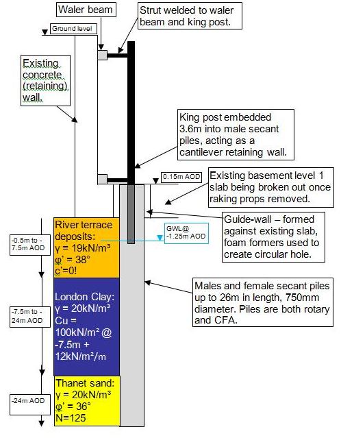
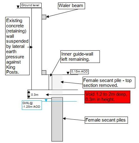
Cross section of secant pile wall, king post propped cantilever and ground model
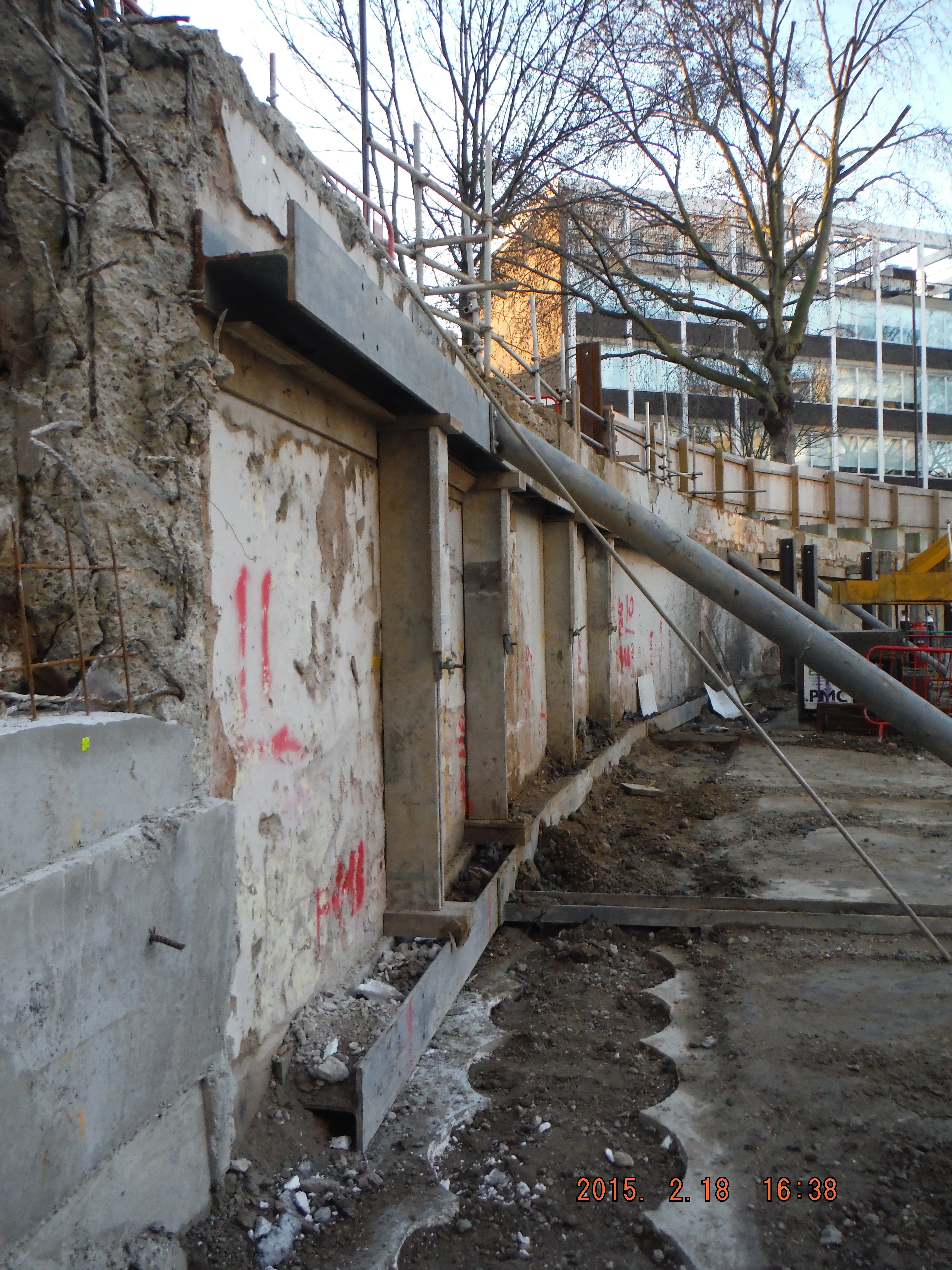
1. Pile Guide Wall (near ground) 2. Raking props to existing slab provide lateral restraint to existing wall (middle ground) 3. King Posts protruding from males secant piles to support existing wall (far ground)
Piling. My role has being to coordinate the piling team to install the piles, specifically where to put king post columns to prop the existing wall up. This just requires thinking about which male and females piles to do to avoid doing them too close to each other and keep the pile rig put of the way of temporary props. Easy in open straight sections, a massive pain in the corners of the site.
Site management. The project is at an early stage so welfare and office facilities are limited. The perimeter hoarding needs to be moved outwards and the live substation needs to be decommissioned after we have set-up a temporary one. Dealing with UK Power Networks and Skanska has been a challenge and I am now very aware of how to excavate around live services (Skanska operatives, however, seem less keen on digging by hand when within 500mm of services…)
The hoarding move is progressing, but add in moving kentledge blocks close to a 3m deep excavation and a busy bus lane/rat run/cycle super highway there is room for error. Mitigation has been practical though – specific site safety briefings, inductions, lifting plans, segregation fencing and common sense, resulting in steady progress.

Right – hoarding moved within 300mm of blue cycle superhighway Left – heras fencing located where hoarding will be moved to. Note kentledge blocks and proximity to edge of excavation (H&S issues for slinger)
This week I have delivered my first tool box talk – pile mattress construction. Some good revision into the Design Manual for Roads and Bridges (DMRB) (thanks Richard), roller weight, type and width and I am about there. I have learned it is cheaper to order 6F2 (thanks for details of what it can contain Guz/Richard) on a “back load” as we are removing spoil daily. £120 compared to £160, thus making the project manager happy. I am also learning construction terminology: A skip “exchanged” means a fresh one replaces a full one and a skip “collected” is a skip taken away. Apparently “takeaway the full one and bring an empty one” is all too confusing!
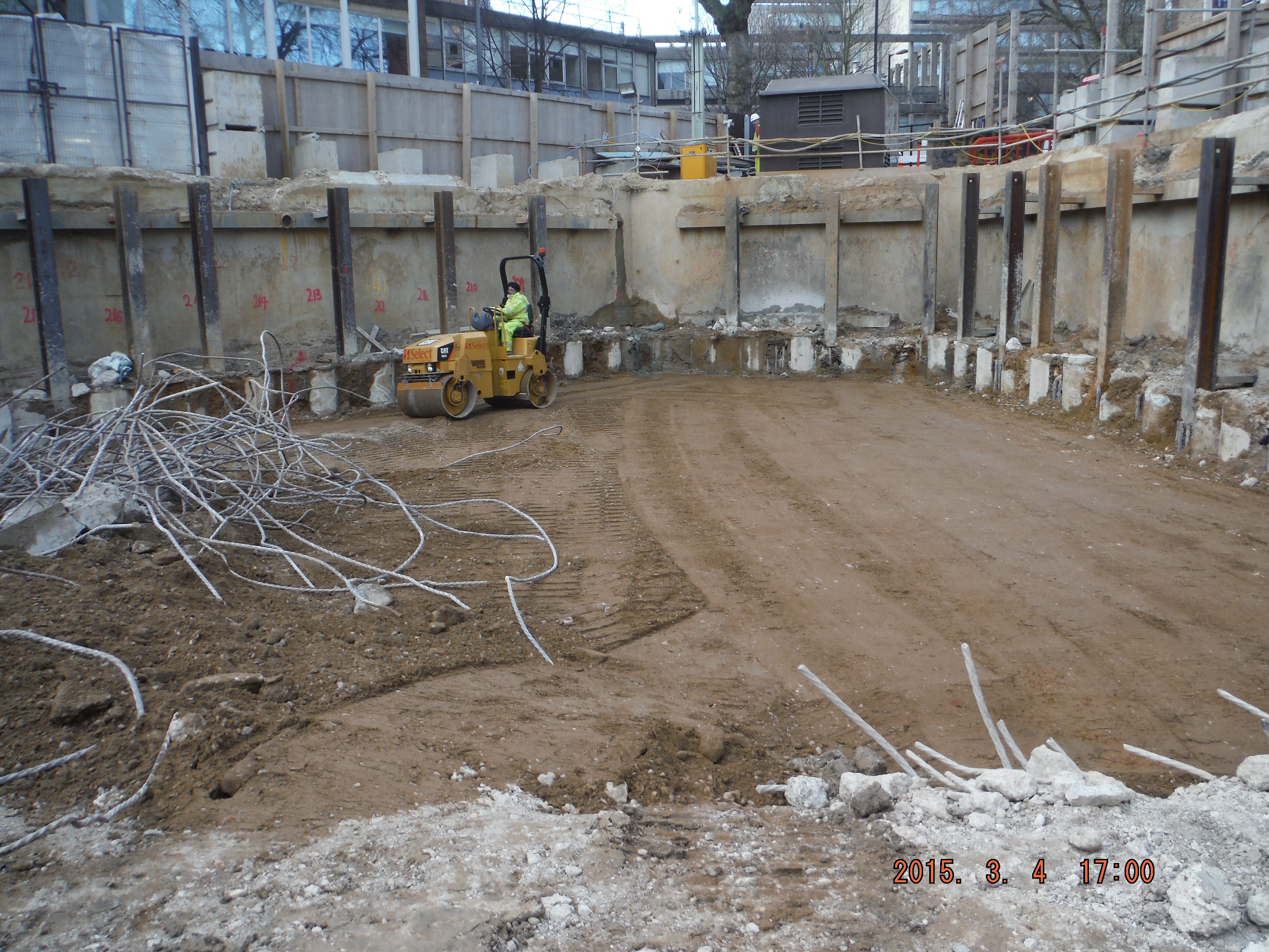
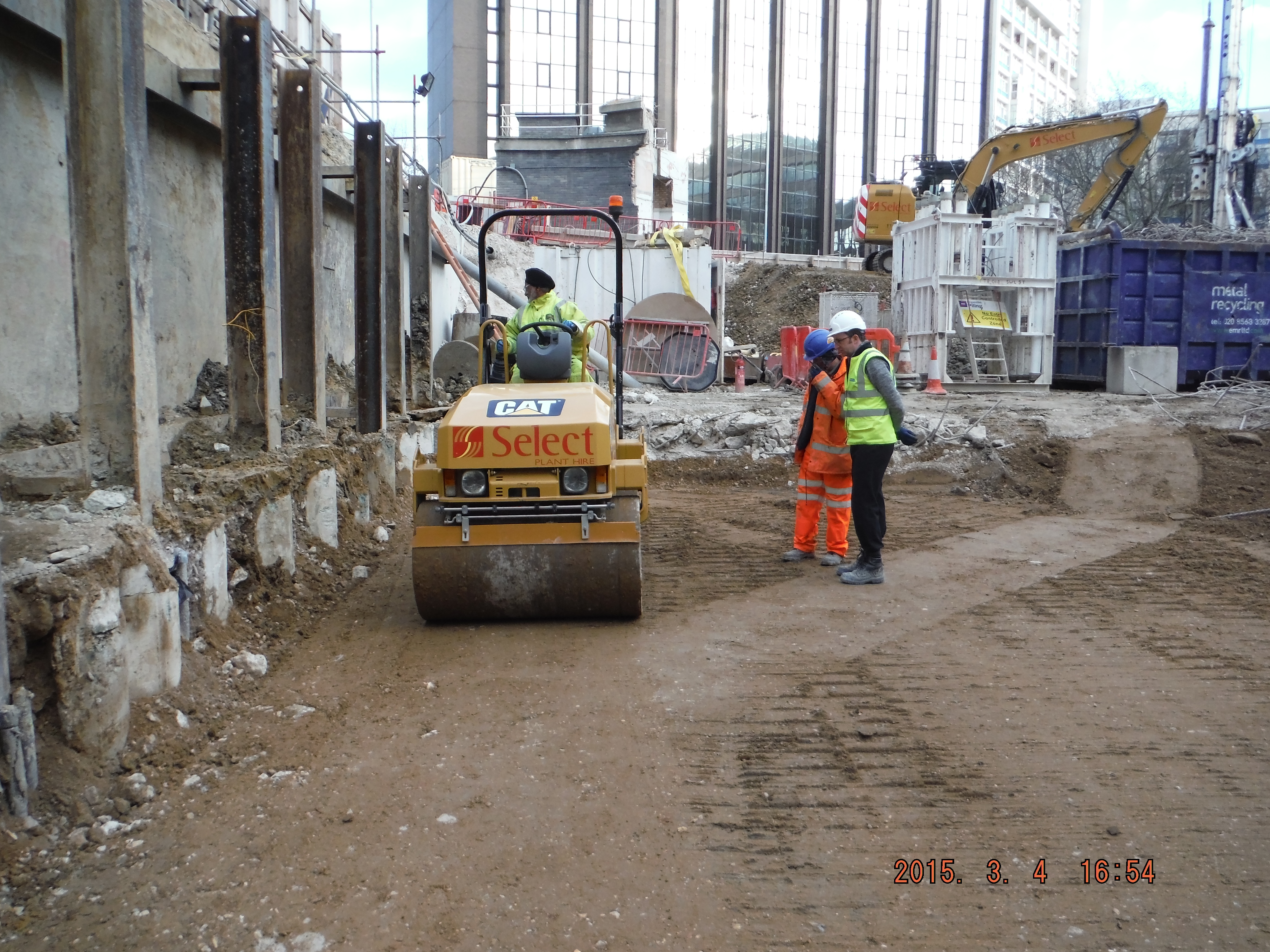
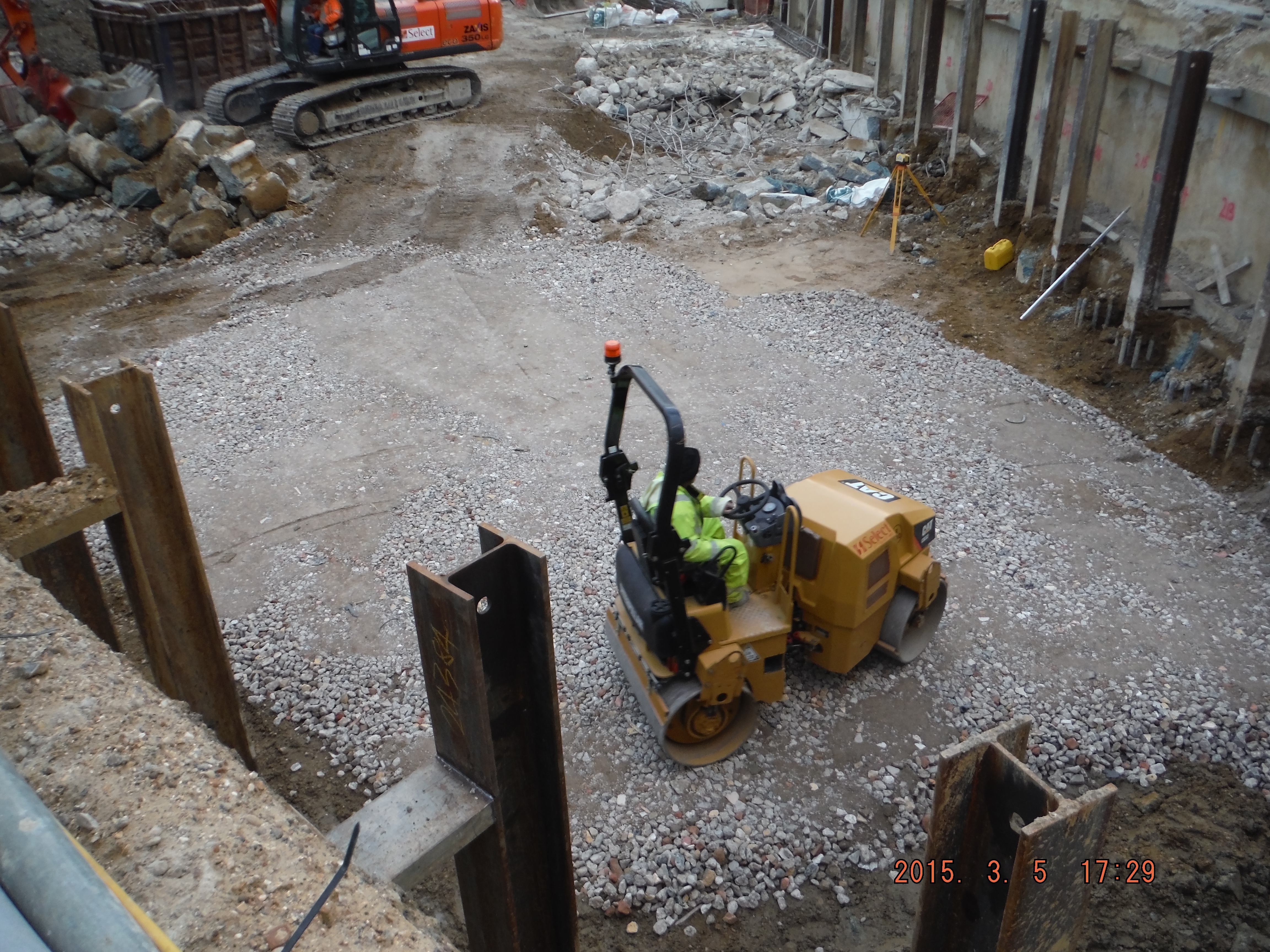
This photo shows compacted river terrace deposits. Rolled with vibratory roller – note depth of compaction – exactly 150mm @ 5 passes – as per the DMRB, now for the 6F2…
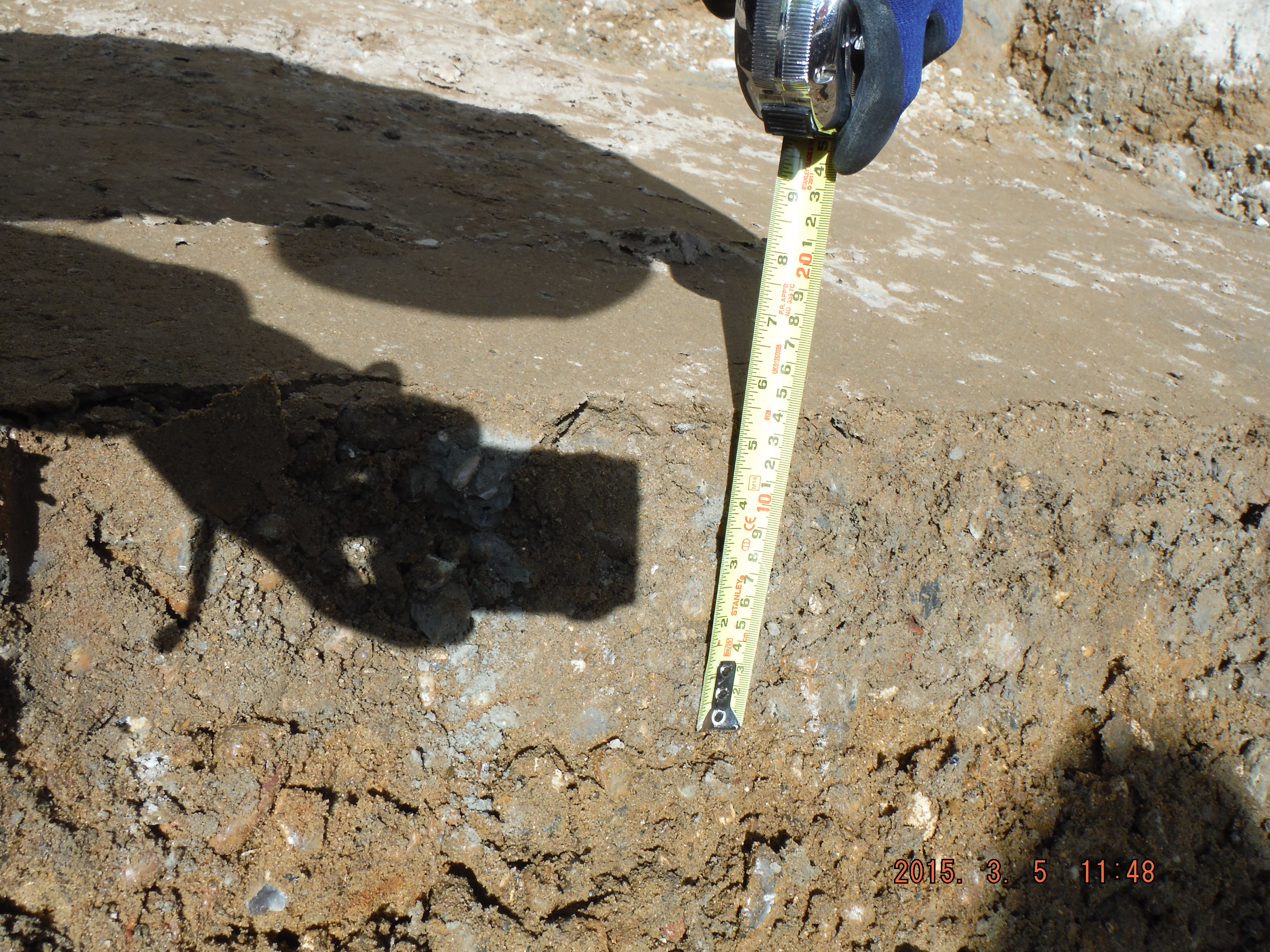
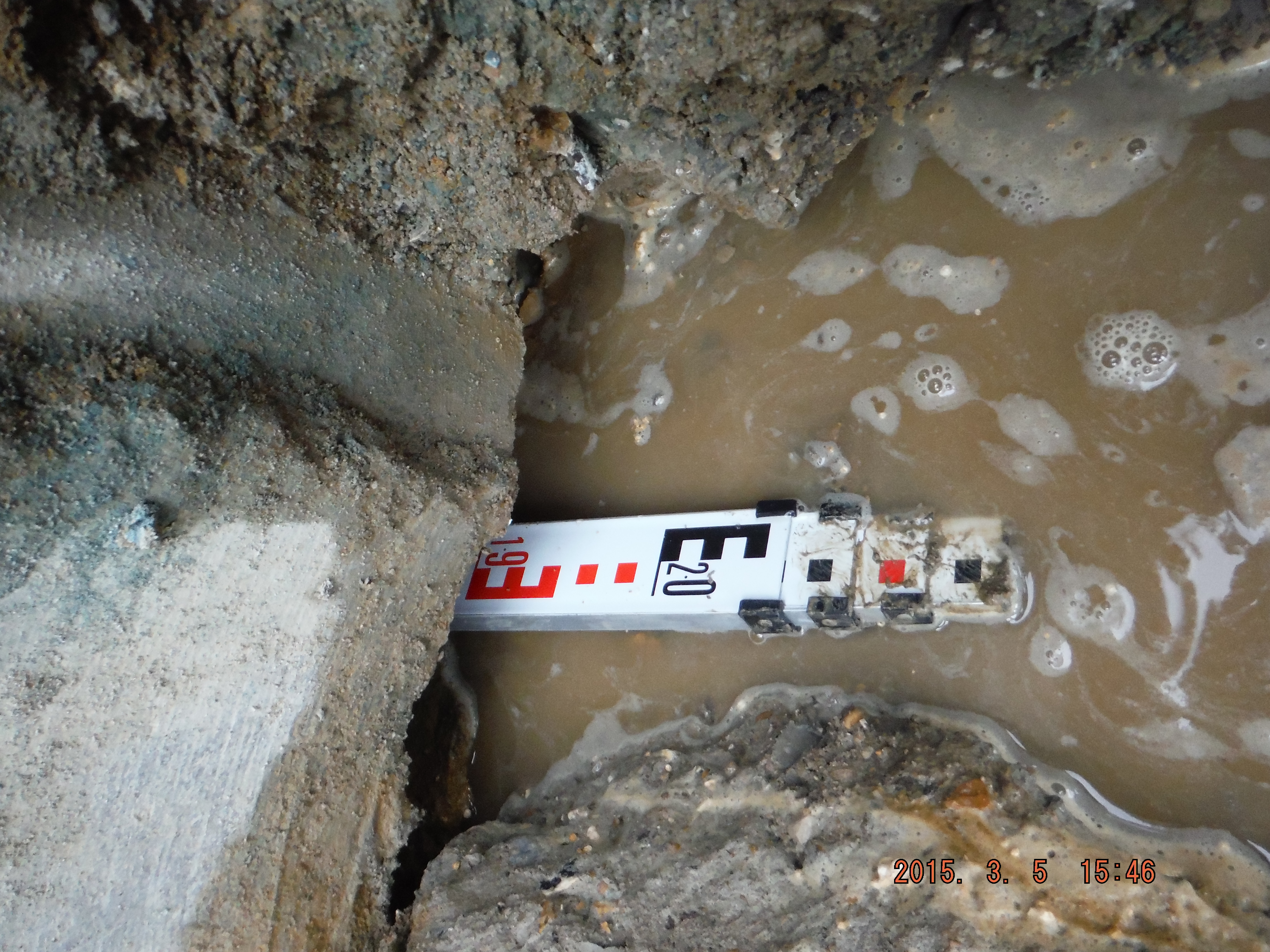
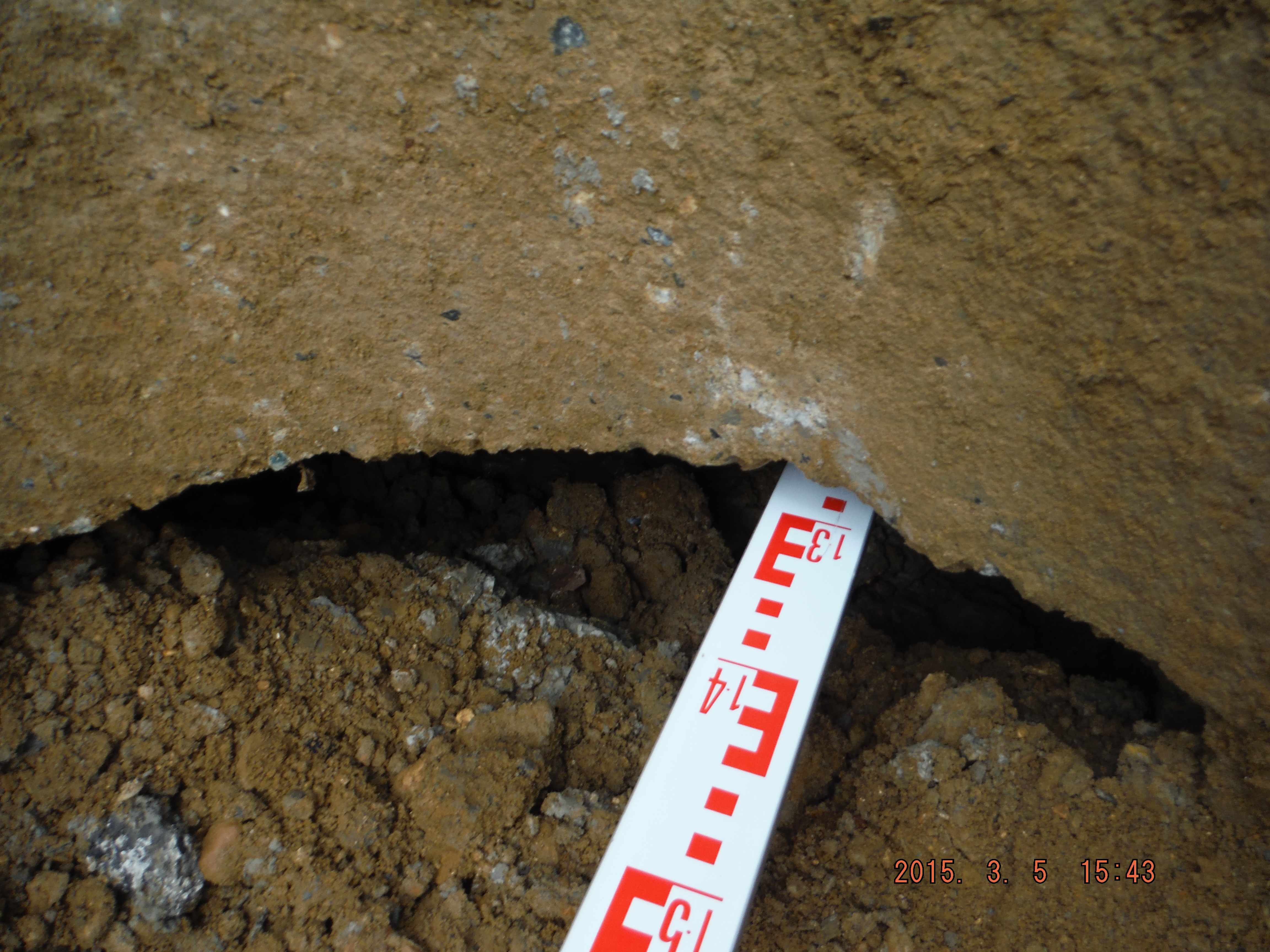
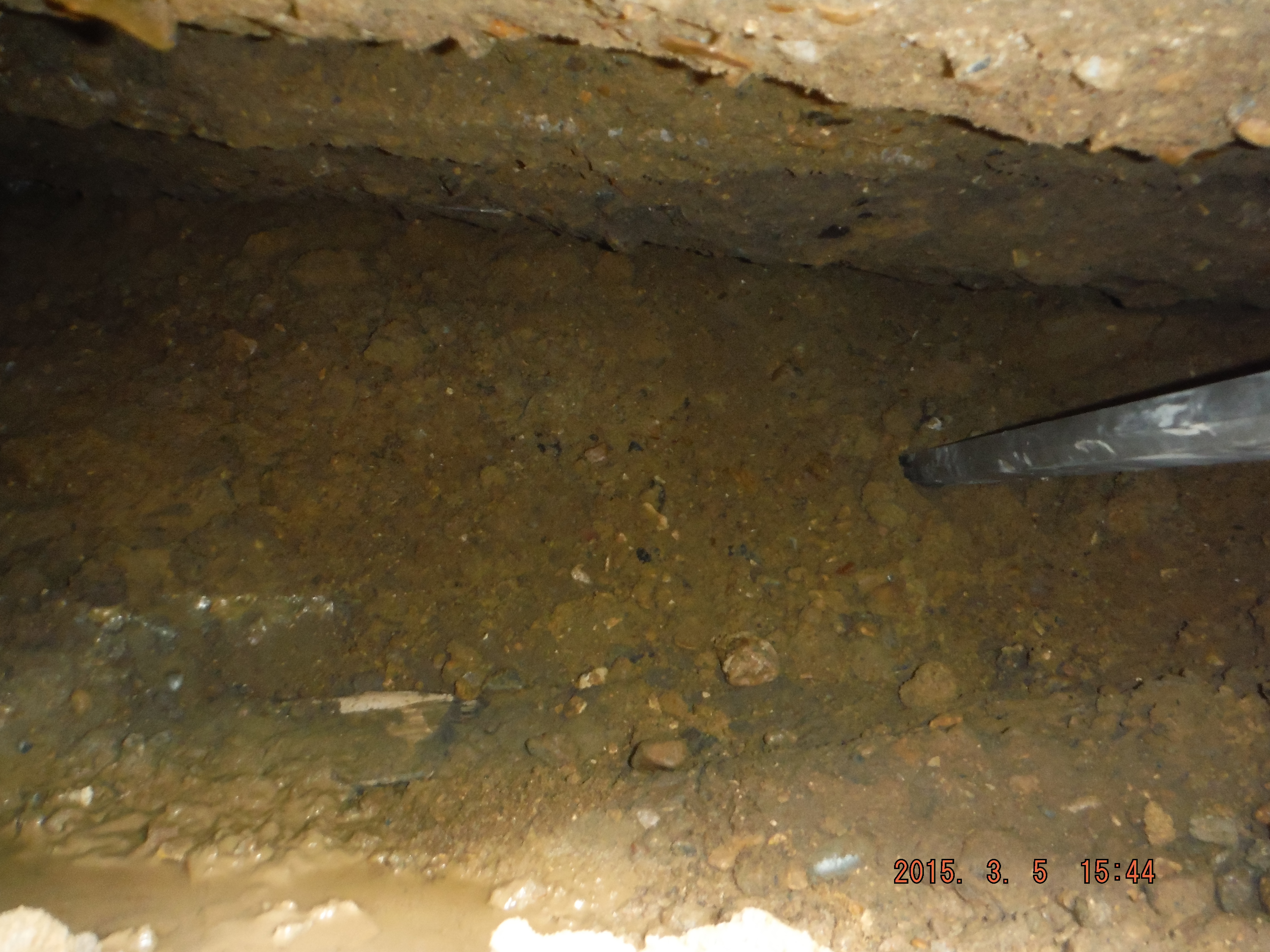
Now for the second part of the pun. After removing the pre-existing slab and some female pile heads it appears I have a floating wall. Well a wall being held up by lateral earth pressure resisted by the king posts and secant pile wall. The hole is about 300mm thick and 1.2 to 2m deep into the underside of the wall.
Cross section of existing wall and void identified above female pile which extends up to 2m underneath the wall.
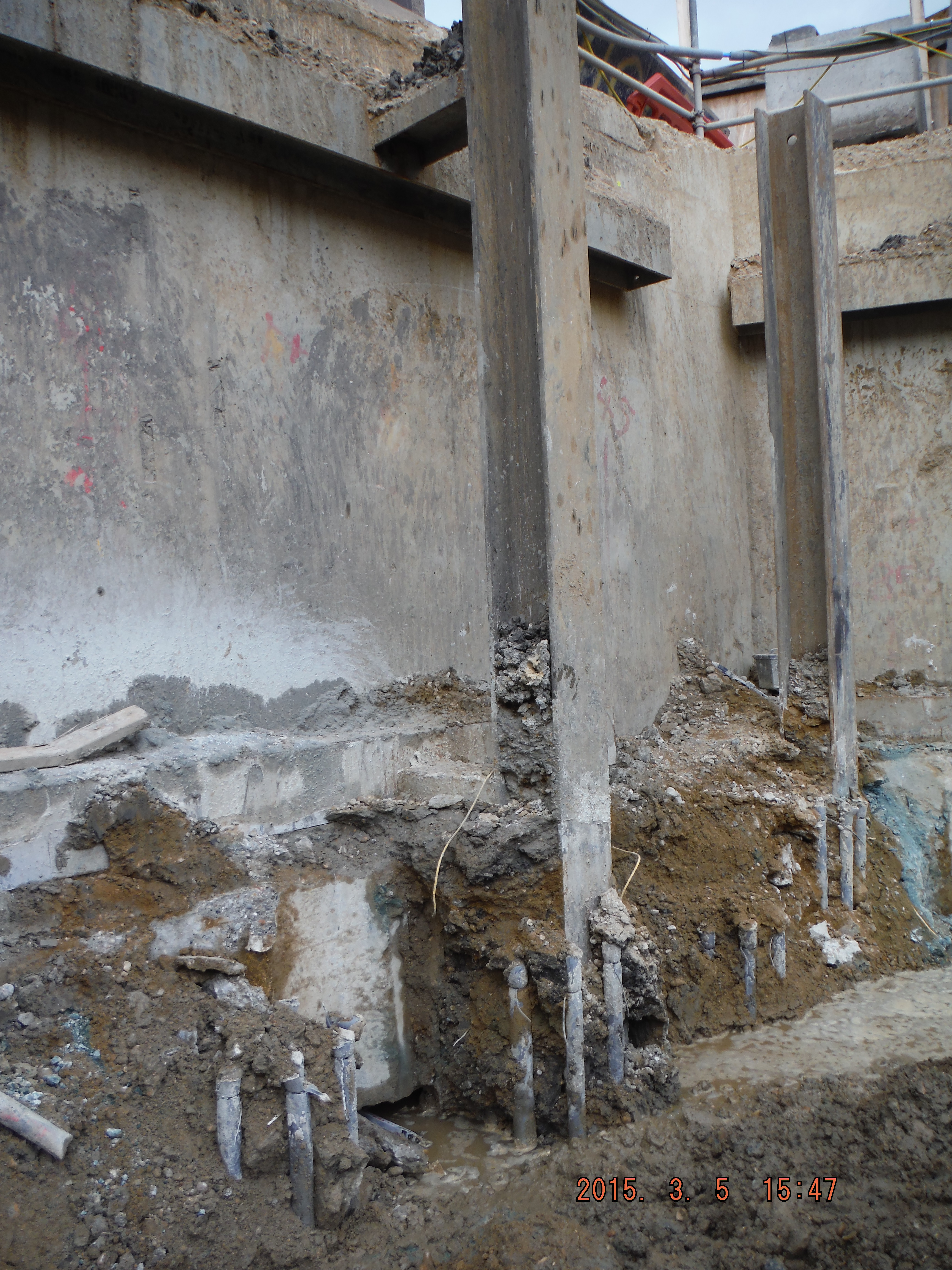
King post protruding from male pile. See void hole to left of king post, between the 2 sets of pile cage reinforcement.
Eventually I had planned to underpin the wall against loose debris in order to construct the capping beam. Looks like that won’t be a problem anymore. Looking into the hole it looks to have been there some time – perhaps the void formed due to water running next to the old slab washing the sand/gravel away (not sure where it has gone to though).
So what to do about the hole… Letter box fill – simply fill the void with concrete from above to close up the void. In the meantime there is already a weekly survey of the wall (mainly to check for deflection into the site, not subsidence of the wall) which has shown almost no movement so I am hoping that it remains that way for a few days longer. We only found the hole today so I am yet to resolve the issue, but as a consideration, if filling with concrete is done it’s roughly a volume of 1.4m (average) by 0.3m thick and extends along about 50m of perimeter so 21m³. Assume £100 per m³ and we are talking over £2000 at this stage and the void may well continue further around the site. Not huge but who pays, client, subcontractor or main contractor…
Progressive Collapse, and other observations….
Last week I was lucky enough to be sidled onto a 2-day course on Progressive Collapse Mitigation run for USACE structural engineers, organised by American Society of Civil Engineers and delivered by a Californian structural engineer – Jesse Karns. The US defence has spent extensive amounts of money in R&D on this topic, and has encompassed its findings and design approaches for all federal buildings in 2009’s UFC 4-023-03 (Jesse was a major contributor in all these areas). Whilst the UFC is not code, it is a guideline requirement for all US federal construction greater than or equal to three ‘occupied’ storeys.
The US approach had admittedly been shaped by British Standards, so much so that the 2005 version of the UFC was almost a verbatim copy of the BS. However, since then, the US government has invested a lot more money into R&D in this area…admittedly due to force protection risk assessments, combined with increased R&D into seismic issues. I was tickled by a comment in the essay distributed by our very own Atkins secondee: “The UK is currently seen as the centre of engineering excellence around the globe”…really?. Well, after this course and a limited time in the US, I beg to differ. The quote needs some justification, for example – the UK certainly cannot profess to be a centre of excellence on levee design and flood mitigation when Holland sits under sea level with its livelihood relying on flood defences, and the US has over 100,000 miles of levees. Nor can it profess to be on a world stage with regards to seismic design when there is limited risk to design for. Off the back of this, I though I’d briefly blog on the US’s present approach to progressive collapse – where they clearly believe they are the centre of excellence, or is this just engineering arrogance…a bit like why it took 1995’s Oklahoma City bombing and the 2001 World Trade Centre Collapse for the US to really rethink the how rigorous its codes were, despite UK’s lessons from the Fallon Point disaster back in 1968. I digress…
The 2009 version is viewed as a pioneering document that leaves BS and Eurocodes wallowing in design assumptions that are based on weak and outdated research (albeit much of the design methodology has the same basis). I though I’d note the following comments that were in the handout alongside the odd wry smile in my direction …’the mechanics of the methodology are much better defined than British Standards’, ‘the past UFC was based on British Standards and were not too bad for RC (some flaws nonetheless), and really bad for steel’.
So, here’s the lowdown, with some initial figures showing the R&D testing set-up for column removal:
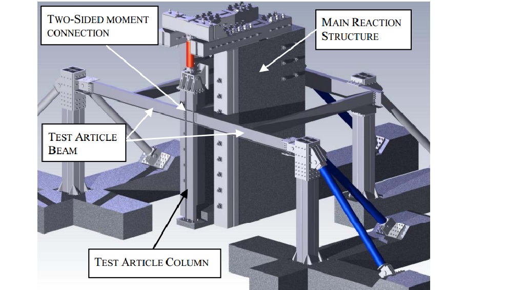
Test model setup for column removal as a result of blast action
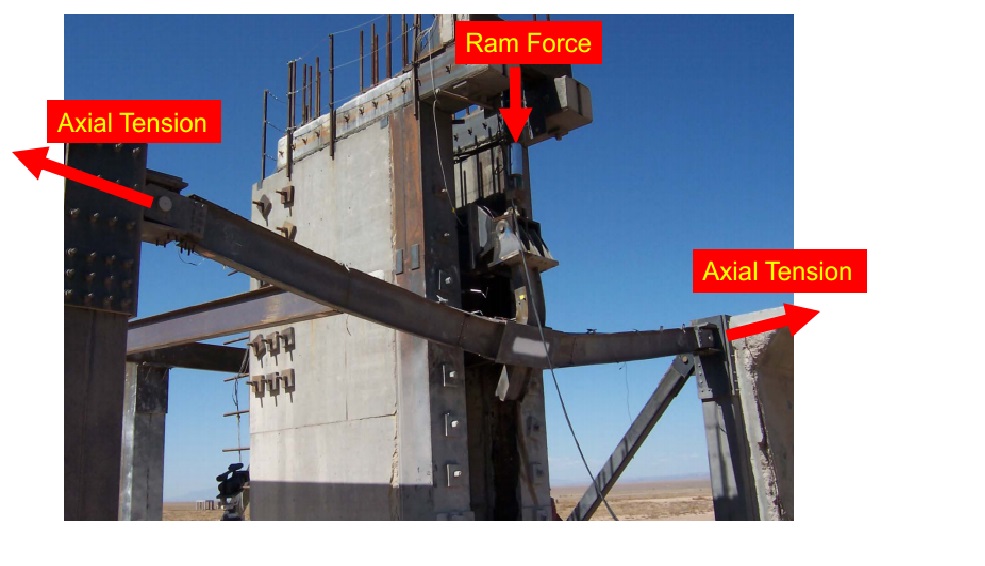
Actual testing post blast (note splayed column)
Design Requirement. As said, the UFC applies to buildings with three of more ‘occupied’ storeys. The design requirements are dictated by an occupancy classification, from 1 to 4 which is relative to consequent impact on loss of life. ‘1’ being structures such as storage or agricultural facilities, and ‘4’ being hospitals, emergency shelters, aircraft control towers. Three design requirements exist:
- Enhanced Local Resistance (ELR). In outline, this is where the shear and flexural capacity of perimeter walls and columns are bolstered for additional protection. It is done to increase the capacity of corner and penultimate columns to resist potential increased lateral forces from tie forces (see below), decrease the possibility that two columns will be removed in an initiating event, and forces a ductile flexural response by limiting shear failure.
- Tie Forces. This British philosophy prescribes tensile forces that hold primary members together. Ties are provided at across each floor level: horizontally (internal and peripheral) and vertically (at columns and load-bearing walls). The theory is based on catenary actions, where internal tie forces are related to beam vertical beam displacement, load and original span length.

- Alternate Load Path. Software design that allows for a localised failure but requires that alternate load paths be available to distribute loads to other undamaged parts of the structure.
The occupancy classification dictates which ones to use e.g. Class 1 – no specific design requirement, Class 4 – Tie Forces, ELR for all ground floor columns or walls, Alternate Load path for specified column and load bearing wall removal
A notable eyebrow twitch came in the results of connection testing. Structural engineers on the west coast of the USA will always design beam-column connections, with detailed drawings. Everywhere east of the Rockies, we just stipulate moments, forces and directions and let the fabricator ‘crack-on’. Why the difference? Well, primarily because of the West Coast’s prevalence of seismic events and the knowledge of how buildings collapse…it has been found in structural studies post 1994’s Northridge earthquake that connection failures have consistently been the cause for progressive collapse. The below graph from tests between 2004-07 identifies the displacement of a central connection directly above a column that has been removed.
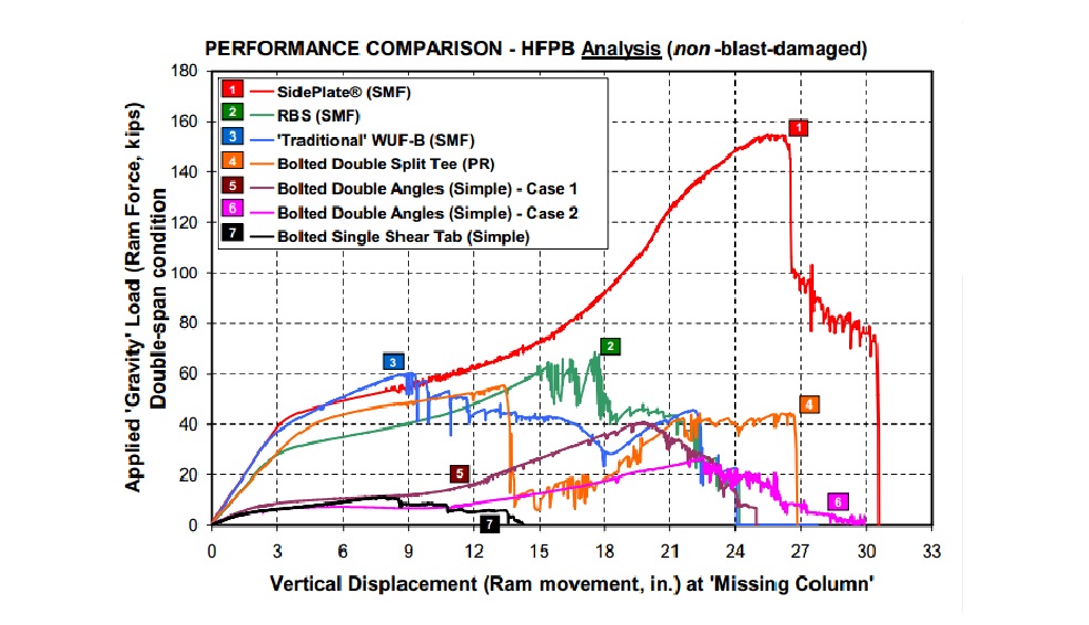
Conscious that we want to harness a beam’s flexural and plastic capacity when considering progressive collapse resistance, allowing it to go into the plastic realm between Fy and Fu (and not beyond), the specific design of connections by an engineer should be essential when considering progressive collapse……
