Just Give It Time
Last week work started on the east bank crane jetty. The ITP requires that the first four piles are to be tested to ensure they will resist working loads. The working load per pile is 2000kN and FOS of 1.5, therefore each pile is required to resist 3000kN (or so we thought, I’ll come back to that later).
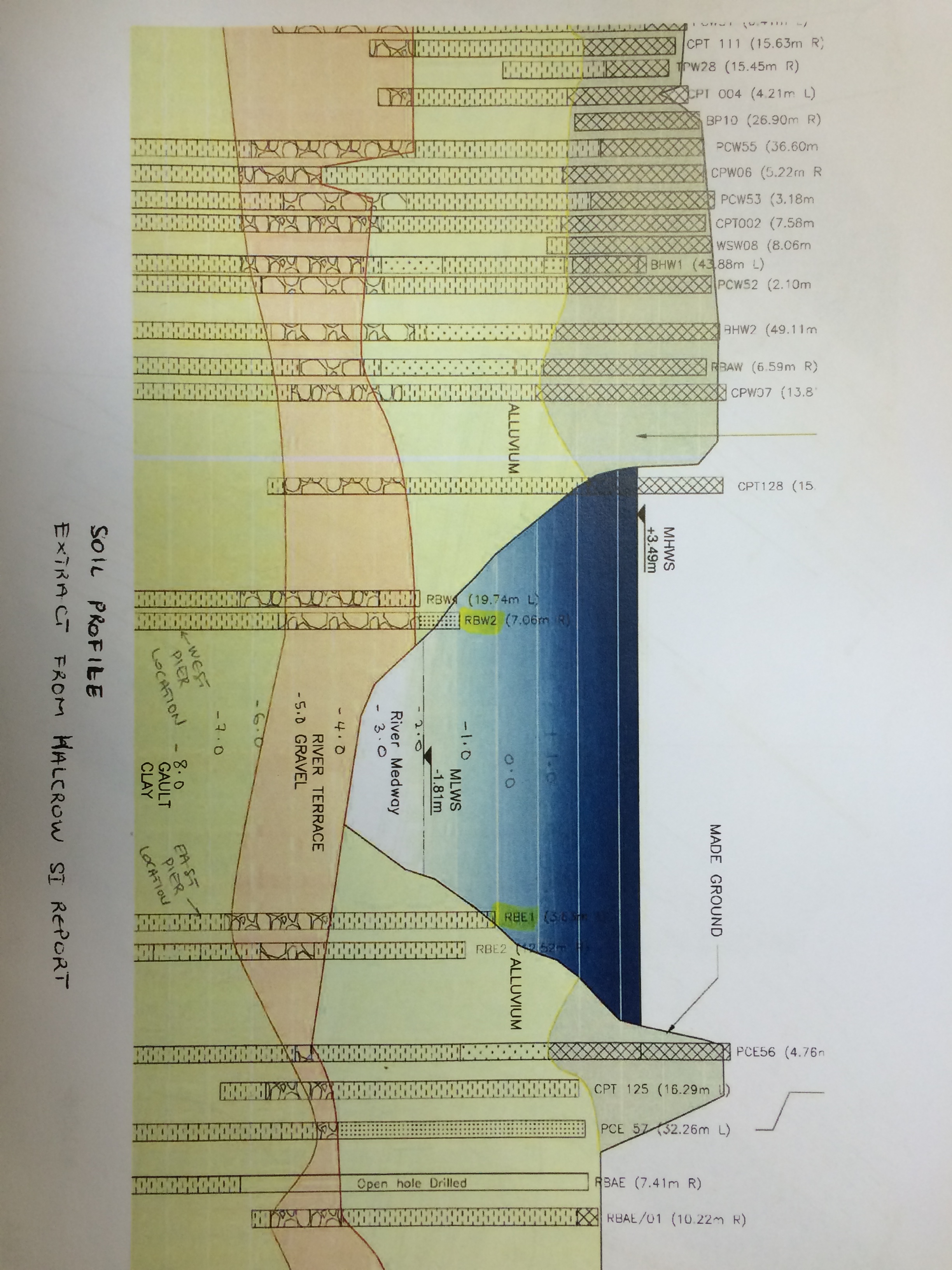
The west crane jetty piles were 18m CHS. The east crane jetty piles are the same tubes however they are 20m in length. The east side of the river has a thicker top layer of alluvial deposits and a thiner layer of terrace gravel which provide a lower shaft resistance through the first 9m than the west side. Below this level is Gault Clay which carries most of the load hence the requirement for a longer pile on the east.
The piling gang were ready to start but the 20m piles hadn’t arrived, direction was given to use some 18m ones we had on site. This decision was based on the fact that the edge of the river is higher and therefore more of the pile would be supported. In reality all the piling gang did was hide steel under some alluvial soup that offered no support.
Once the first four piles were within approximately 600mm of their level a Dynamic Pile Test (DPT) was instructed. This consisted of two sensors being rigged to the pile (see below), the smaller sensor is an accelerometer and the larger a strain gauge. Once set up the pile is then driven further by the hammer. The pile dimensions and the hammer speciation are input into a Pile Driving Analysis (PDA) terminal which then records the results from the sensors whilst being driven. This then produces a window of pile resistance. Our first pile registered between 2700-2800kN, not the required 3000kN furthermore we only had 300mm of pile left before we hit our level.

The technician recommended that we should stop at this point and continue the test the following day. The next day the test was then carried out again on the first pile and it reached 2980kN…accepted! The three remaining piles also passed.
Cue Terzaghi and Mohr-Coulomb
When the pile was driven is caused the pore water pressure to rise. This created a hydraulic gradient. With the gravel the short and long term states are the same however in the Gault Clay they are not. The clay has a very low permeability so on face value I wouldn’t have expected much change overnight however the borehole data from the GI identifies veins of coarse sand and gravel with in the clay and also irregular fissures (although it is hard to know if these were caused by the boring process). The reduction in pore water pressure increases the effective stress and ultimately increases the strength of the clay.
These ‘Case Data’ results were then sent back to the office and run through CAPWAP software. This is a post processing tool that analyses the data from the PDA and refines the results with data from modelling and empirical evidence. The technician suggested we should expect upto a 10% increase in the capacity.
The Game Changer
This whole issue is now almost irrelevant; when the designer was called he informed us that the working loads were only 1000kN per pile so we only required 1500kN. This should have been blindingly obvious. The piles work in pairs and support simply supported beams. So four pile support the 110T crane, its load and the self-weight of the jetty deck. Based on the initial 2000kN per pile that would be in the region of a total load around 800 tons and alarm bells should have started ringing at this stage but everyone just got on and tried to achieve the results required without question.
I’m sure I’ve been told a few times to take a step back, look at the fundamentals and question the obvious before getting too involved……phuf, what did they know!
In other News
Guz – I can now join the ‘what’s the best thing you’ve found in your 6F2/5’ game. Today I found some super squishy foam, a glove and what looked like action mans left arm!

Olly,
Not sure I can quite get my head around the actions you are applying to the jetty to calculate vertical force the piles must carry. Admittedly, if the rig sits in the middle of a 4-simply supported pile ground then each would take a quarter, but what happens when it tracks in and at some stage sits axially over a pile pair, or is that what has been designed for?
Does the crane ever get fixed to the jetty? – I am thinking wind loads would also come into play in such an instance.
You imply a short term increase in effective stress in the clay, therefore longer term, do you suspect the clay will settle significantly as the effective stress reduces? Not sure how long your temporary jetty will be there, but I suspect same applies to actual bridge. What is the predicted differential settlement – if east and west piles toe into different lengths of soil horizon, one more into clay – is that an issue in the longer term?
Damo – I don’t have access to the design calcs so I’m trying to reverse the thought and design process. The crane jetty will be in for around a year. The crane is a crawler and never fixed in place. The side profile of the jetty is low and when we have high wind the crane is moved back to the launch so wind loads will be small. Longitudinally the crane is kept central by wooden blocks which means its load is always distributed evenly between pairs of piles (when no load is slung). It crawls very slowly on the deck and is not allowed to travel with loads suspended so we have a feeder crane to pass materials out to it. You rightly point out that the greatest load a pile would experience would be when the crane sits directly above but that would mean a pair of piles have a 2000kN capacity which still sounds correct…
1100kN crane + 200kN max crane lift at required radius + self weight of the deck, I have just through some very rough numbers together and came up with between 450-600kN based on different steel sizes = <2000kN
Granted this does not take into account the effect when the crane has a load slung out to the side which would favour the loading onto one pile over the other, however, based on my rough fag packet numbers I still have a little in the pot. This would mean the total is a little over 1000kN for the worst loaded pile which is a long way form the 2000kN the site engineer was told we needed to achieve.
The piles are hollow tube with out a shoe, so whilst they do displace it is not to the same degree as if they were solid. This will limit the rise in pore pressure. The west crane jetty has had its crane on it for six weeks and settled a few mm in initially but is monitored regularly and is stable. Regarding the east jetty I suspect that the marginal rise in pore pressure will reduce in the short term through the natural features and the jetty will have calmed down very quickly after it is completed and fully loaded.
Olly,
Good blog and good topic, I’ve done a TMR on dynamic testing and am attempting to write a thesis based around it. The setup that you see when restriking the pile after a day can be quite dramatic (dependent on the soil conditions). Different studdies have recommended different timeframes for conducting a restrike. These vary from 15 mins to 2 weeks. The most balanced approach is waiting between one and two days, as this gives a closer approximation to the long term capacity of the pile, without delaying the construction program too much. Were you using a PDM at the end of drive in addition to the PDA (to take the set measurements and rebound)?
If you want any more info on dynamic testing let me know and I can forward on a whole bunch of stuff.
On the crane planning, who is designing the lift – is it the crane subcontractor, or is it completed in house? With crawler cranes the worst case bearing pressure can sometimes occur when they are not carrying a load, but have the jib fully up. I’d expect the operator to know this and track out with the jib at a sensible angle, though it might be worth checking the lift plan to see that they checked the load through the full slew of 360 at the worst case radius. The piling subbies that we had on site brought their own lift plans that tended to lack a lot of detail. Another one to check is that they are using the same rigging on site as they have on the plan. If the switch from polyester slings to chains then this can add a significant weight to the lift. There are a number of planning tools that the major crane suppliers make available free of charge to help design lifts for their own cranes (if you ever get asked to do this, let me know and I’ll pass on some helpful templates).
Pete,
Thanks for your points regarding short term changes in pile resistance. I was surprised by the rapid increase and even called John prior to posting the blog, he mentioned you had experienced similar.
We weren’t using a PDM, in fact I’ve just had to do some research to find out what one was.Throughout the testing period one of the apprentice engineers was surveying the drop and counting blows, all of this was then sent back to our temp works design office (in house) for the set to be authorised.
What aspects did your TMR and Thesis explore?
Currently we have three crawler cranes operating. All of the lift operations are planned in house. Our sheet and tube piling subbies have got an AP with them and have their own lift plans but they have been check and sit with in ours. A bore piling gang have just arrived who are writing their own lift plans, I have to admit that they appear to be a much more professional outfit on face value. The complexity of cranes hit me yesterday when I started writing the method statement and risk assessment for the excavation of the cofferdam, I am very much learning hour by hour at the moment. When our crane tracks it lowers its jib to around 3/4 ish height which may tie in with your point about max load when the jib is high. I will ask in due course.
The crane planning tools would be useful, whilst I am not being ask to do anything like that at the moment it is useful to understand the planning parameters so that I’m not expecting the imposable.
ojchild@gmail.com
Great blog!
How was the specification worded? Was it misunderstood or badly worded? If you were only driving to achieve the lesser resistance would you have saved significant time and it cost?
On another vain loving action man’s arm, that might even beat Ange’s toilet seat!
Installation method.
1. Drive 4No 20m piles to level and test for resistance.
2. Submit details to the temp design office to be issued with a set (mm/blow) for the remaining piles to achieve.
3. Drive all remaining piles to set
You’re absolutely right, if we were trying to achieve the lesser between a level or a set then this could have paid off and saved time and material however these were the first piles and know one really knew what was going to happen.
After I blogged it all got a bit messy, the designer called back to say it should have been 2000kN. Not a problem you may say as we achieve that with the FOS added however, more piles had then been installed which couldn’t achieve the required set they had issued…
I’m going to follow this up in another blog but lets just say it opened the door to my first big lesson on site!
Went out with my phone later on to photograph action mans arm but sadly the final layer of material had been laid. The legend lives on!