Archive
Site Two Fifty One – In the thick of It
Site Two Fifty One – In the Thick of It.

Capping beam steel erection.
I have mentioned before that one of my roles is the installation of the capping beam which runs the full perimeter of my site (180m). The steel for the first 35m arrived on Monday to culminate a design development of something I have been responsible for since arrival. The capping beam will have an in-situ wall sitting on it and a basement slab spanning from it. Additionally, for about 5 months, it will be used as a beam to prop off in order to excavate one storey down.
Groundforce propping plan (click to open pdf): 1728 101
So there are elements to the installation which have huge consequences if not correct.
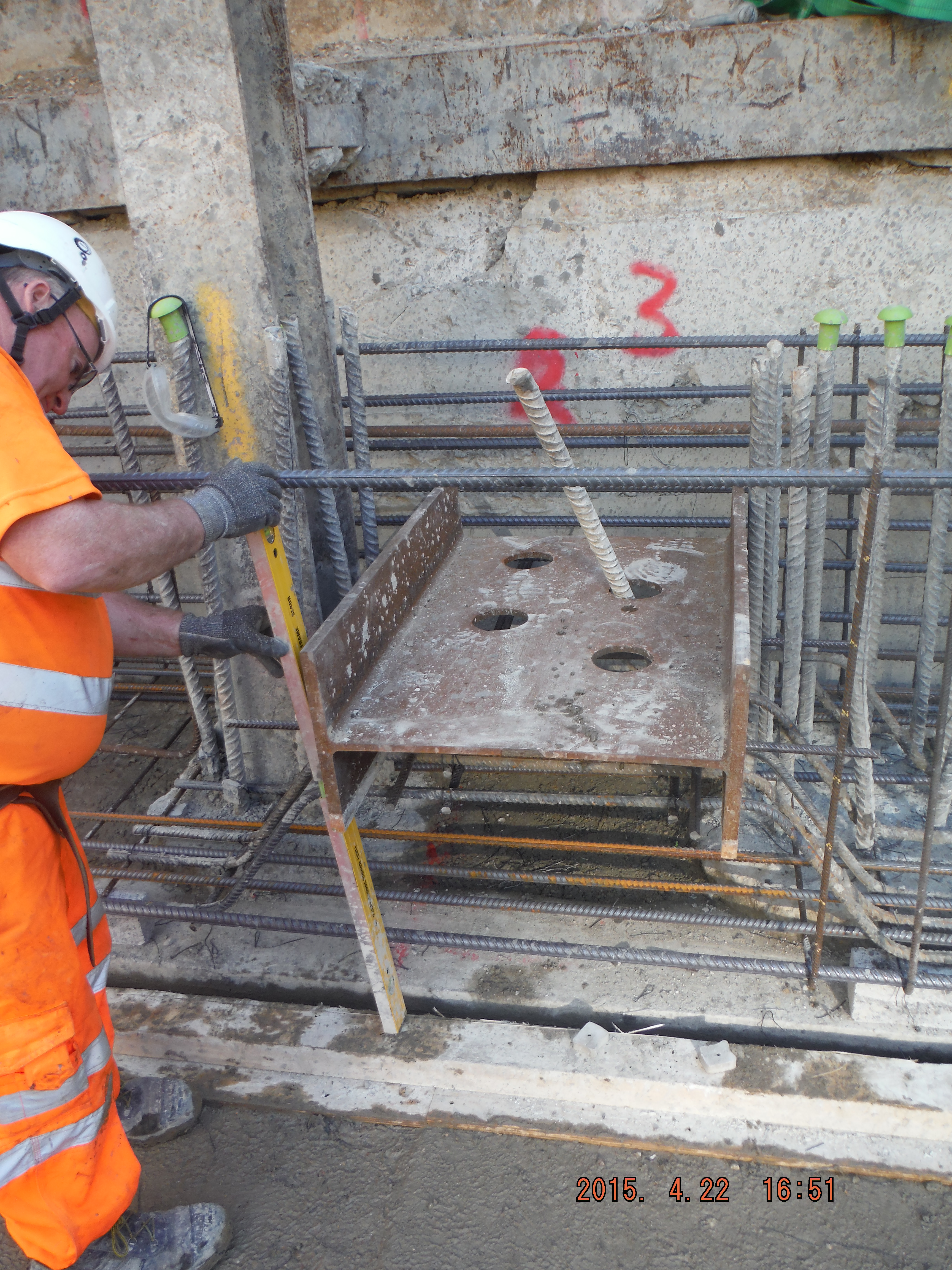
Single shear stub.
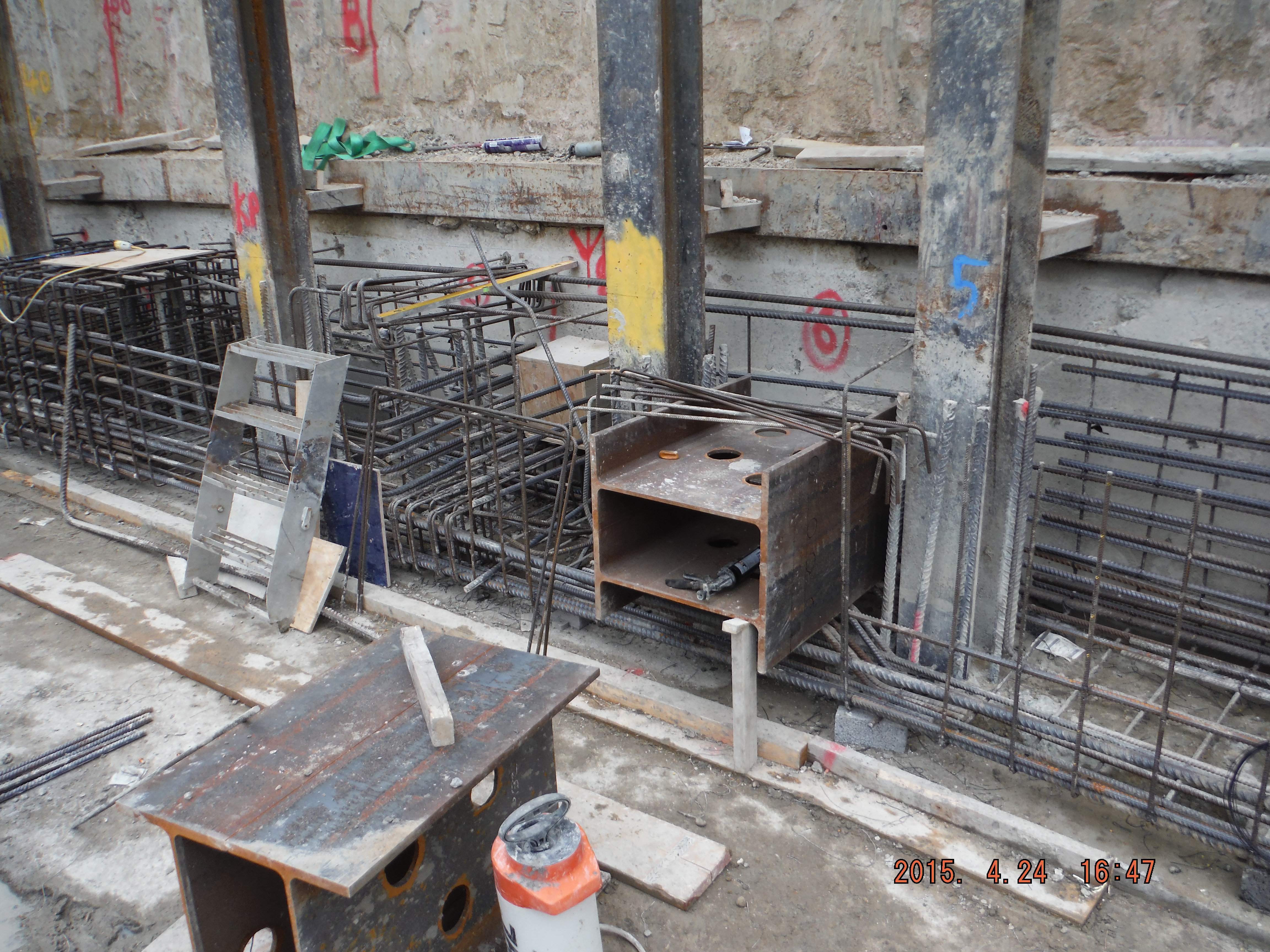
Double shear stub.
There is a drainage duct which protrudes through the beam and there are umpteen ‘king posts’ column sections retaining the old retaining wall behind.


Drainage pipe location (left). Bent bars around drainage position (right).
All in all, there is lots going on. The capping beam steel has been digitally modelled, which has 2 advantages. 1. It helps understand how it fits together and 2. The steel schedules are produced from it (Tekla software) which can be used directly by the steel supplier, rather than a person re-typing a pdf document.
As a task, perhaps initially seemingly pretty minor, there are actually numerous considerations:
- Sourcing of steel (Laing O’Rourke will only purchase from Europe although many steel suppliers source from China because it’s cheaper).
- Delivery method: pre-slung or stacked for slinging on site. Method of lifting (crane, excavator), LOAFs.
- Length of bars for working in congested areas (more lapping versus ease of installation).
- Stop ends (max pour size is 40m3.) Use of hirib to avoid scabbling.
- Prop end plate locations and bolt hole positions.
- Formwork design (yes concrete pressures for a 1.2 high beam is important).
- Resource management (lead times, timber, concrete, steel, tools and equipment)
- Concrete – waterproofing.
- Future slab starter bars (kwika-strip).
- Labour management (steel fixers, carpenters, labourers).
- Dewatering (bottom of blinding is at ground water level): sump pumps, discharge permits, siltbusters.
- Concurrent adjacent activities: sheet piling, CFA piling, muck away, welfare establishment, ramp movement).
Reflections.
So far so good, just. It is pretty much construction by just in time design. This means I am getting drawings hours (sometimes minutes) before they are needed on site. This means being familiar with bar mark notation, real detail in why shear links are here or there is key. In reality there are good people to answer my RFIs (temporary works department, Groundforce shorco, digital engineers, steel supplier (Midland Steel), the designers (Waterman)) but there are always pressures to deal with on site. Line and level of shear stubs for props, drainage duct location and invert levels and actual position of the capping beam itself.
It is hugely rewarding to see something you have been involved in start come to fruition, albeit the first big test will be my shuttering design! The concrete pour is planned for next week so no doubt the grey stuff will soon feature.
I think running the execution of the capping beam is a great chance to learn how things work before the significant challenge of the basement slab (entire site) comes along.
In other news, there has been the first working load test on the office piles and a section of site has had sheet piles installed to act as a replacement retaining wall (where the old substation was).

Pile working load test (as Pete predicted!). No further details yet.
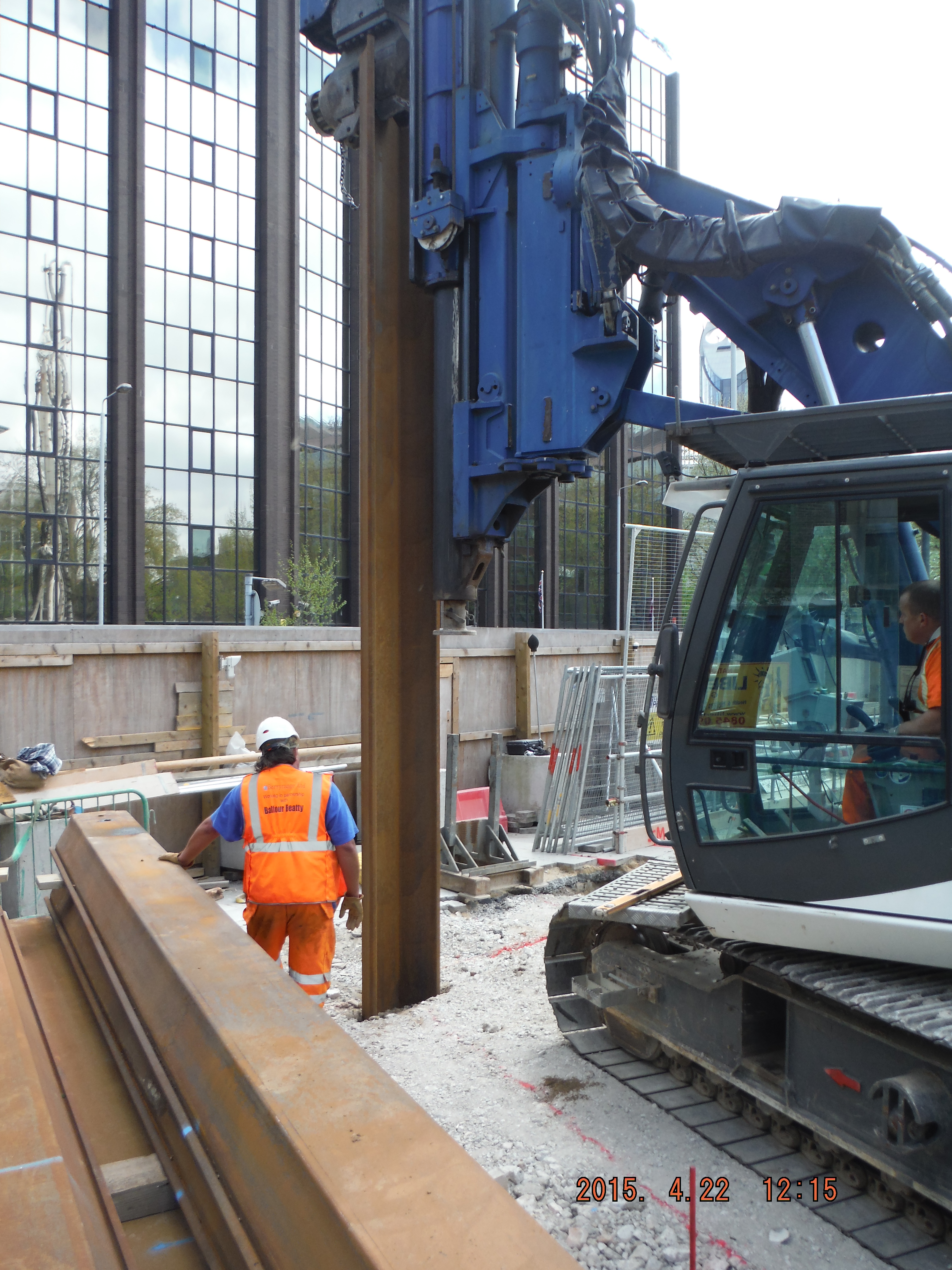
Rotary bored (tick), CFA (tick) and now a bit of vibratory sheet piling.
