Archive
Two things are infinite.
Einstein said: ‘Two things are infinite: the universe and human stupidity; and I’m not sure about the universe.’ This is a theory I have long signed up to and today I can add another piece of empirical evidence to the data set.
One of the Access Control Points (ACP, or gate in English) to the camp at Harrisburg is being upgraded because of the perceived threat to the site from terrorists. On the security front I could wax lyrical about the fact there is a small airfield adjacent to the camp, that it has the lowest grade of fence in the U.S. military catalogue, or that I could squeeze through a gate on the Northern side of the perimeter fence. But greater minds than I have decreed that the weakness is at the main gate so that is what is being upgraded.
As part of the upgrade the road layout is being adjusted with an alien feature to American roads: a roundabout. I have seen less than 10 roundabouts (or traffic circles to use the vernacular) since being out here and each appears to have its own rules. People also appear to be petrified of them, probably because they are so rare and non-uniform. Because the construction is taking place on an operational road building the roundabout has been phased. It also means that everyone has driven past it for the last two months; which is probably enough of a lead up to know what might happen one day.
On Monday we signed of the transition to the next phase of construction and as a result the traffic route was changed in the afternoon for the next phase. Traffic now enters the camp in a different lane weaves about a bit and then hits the roundabout. To be more precise, only half the roundabout and the idea is obviously that you go ‘round’. So without looking at the artist’s impression below you can probably guess what happened this morning.
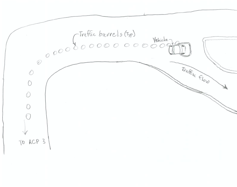
My Boss’s sketch of the incident (cameras were banned for security reasons)
A driver had managed to mount her car on the triangular lane splitter at the entrance to the roundabout. When in full operation this apparently shouldn’t be catastrophic as the kerb is ‘mountable’ and the level inside the triangle will be brought to the top of the kerb with concrete. At the moment, half constructed, the inside of the triangle is at road grade level, about 8 inches short of the final level. As she tried to reverse out of trouble she broke off her bumper and has apparently damaged her front axle assembly and because of that the car is ‘totalled’.
So what..
Well it lead me to thinking what could we have done about it. Filling the hole in would have reduced the damage sustained to a vehicle but would have caused rework or having to order in concrete. In the end more cones were placed in the triangle to ‘give more reflection’ as the driver said she hadn’t seen the kerb. My opinion is that more flashing lights and reflective bollards aren’t really going to help if someone is looking at their phone rather than the road and that human nature is always going to cause the odd accident. The best prevention of a future accident is the fact that everyone driving in that morning will have seen the car stranded and might be more vigilant: for a few days.
Fortunately no one was hurt in the accident, something I should have mentioned earlier. This was because, by chance, no work was being done in the area. Maybe, as a safety measure in the future though, a soak time of a couple of days after a road layout change might be a sensible safety precaution in an area where commuters operate on autopilot in the mornings.
The below pictures show the phases of construction for the roundabout. The accident happened in the phase 2 layout moving from the top of the image.
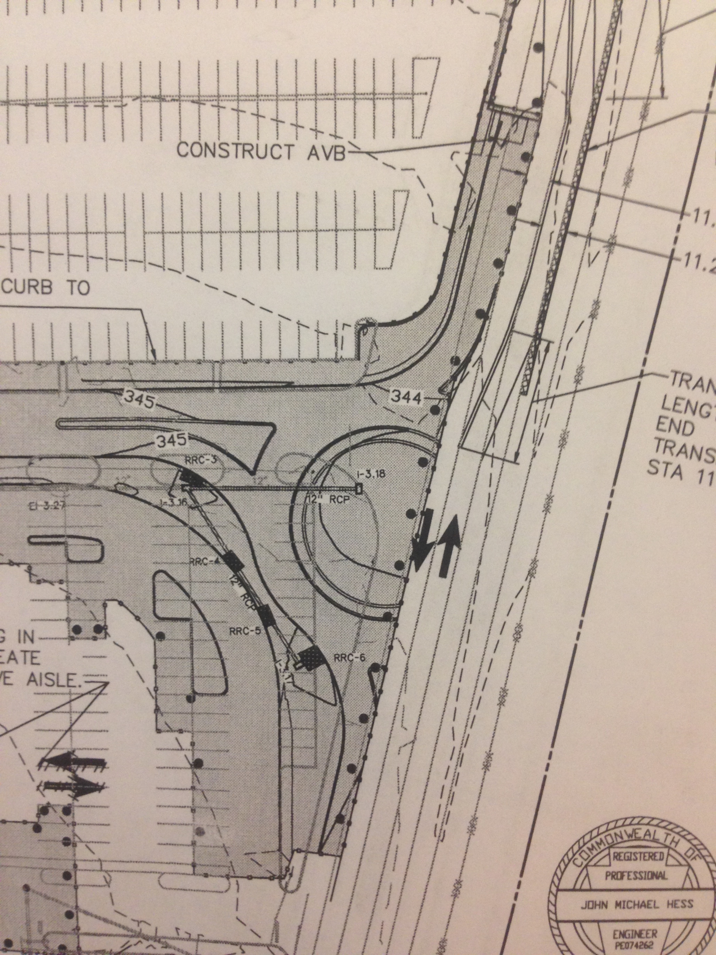
Phase 1
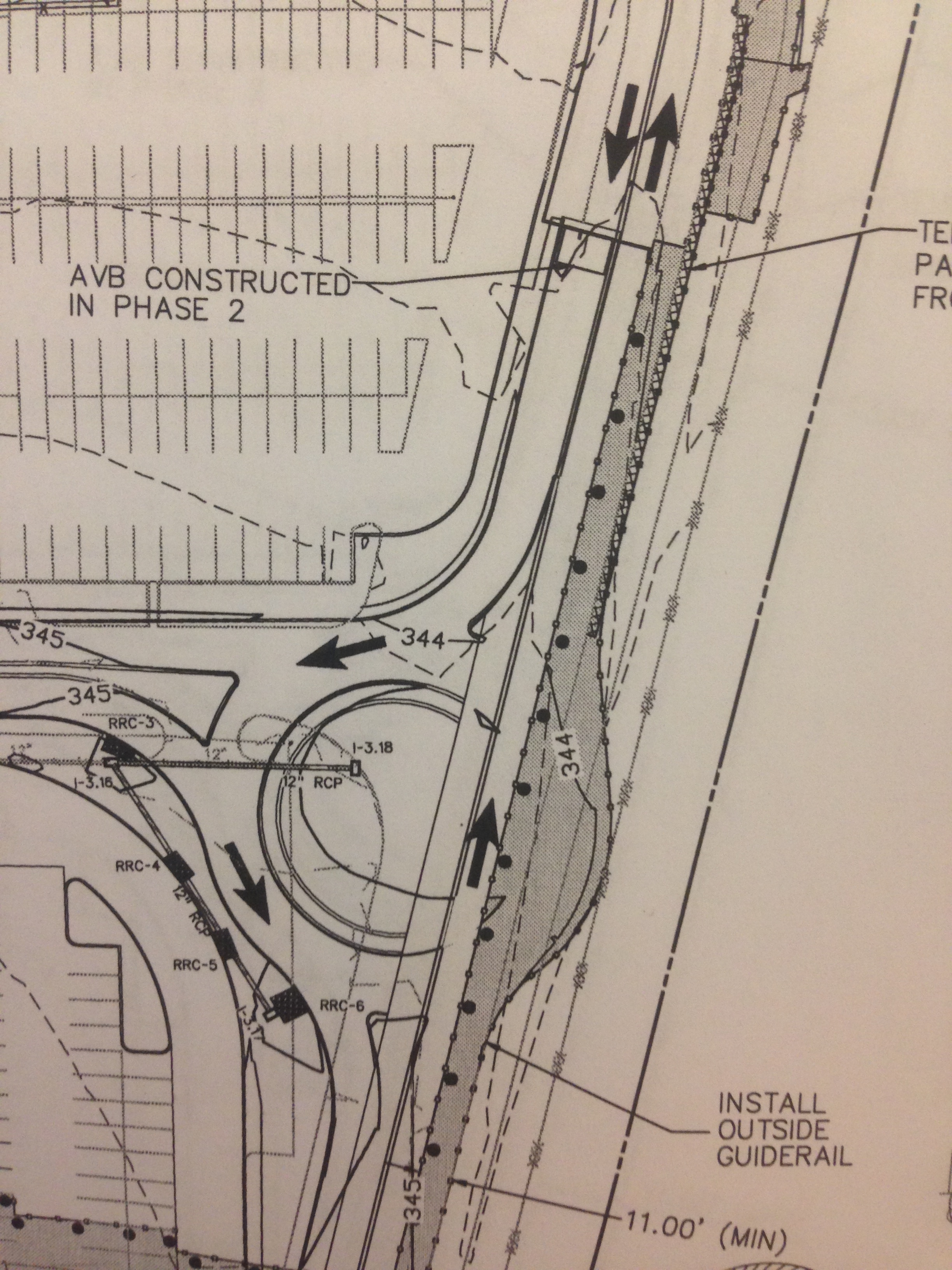
Phase 2 – the phase we have just moved to
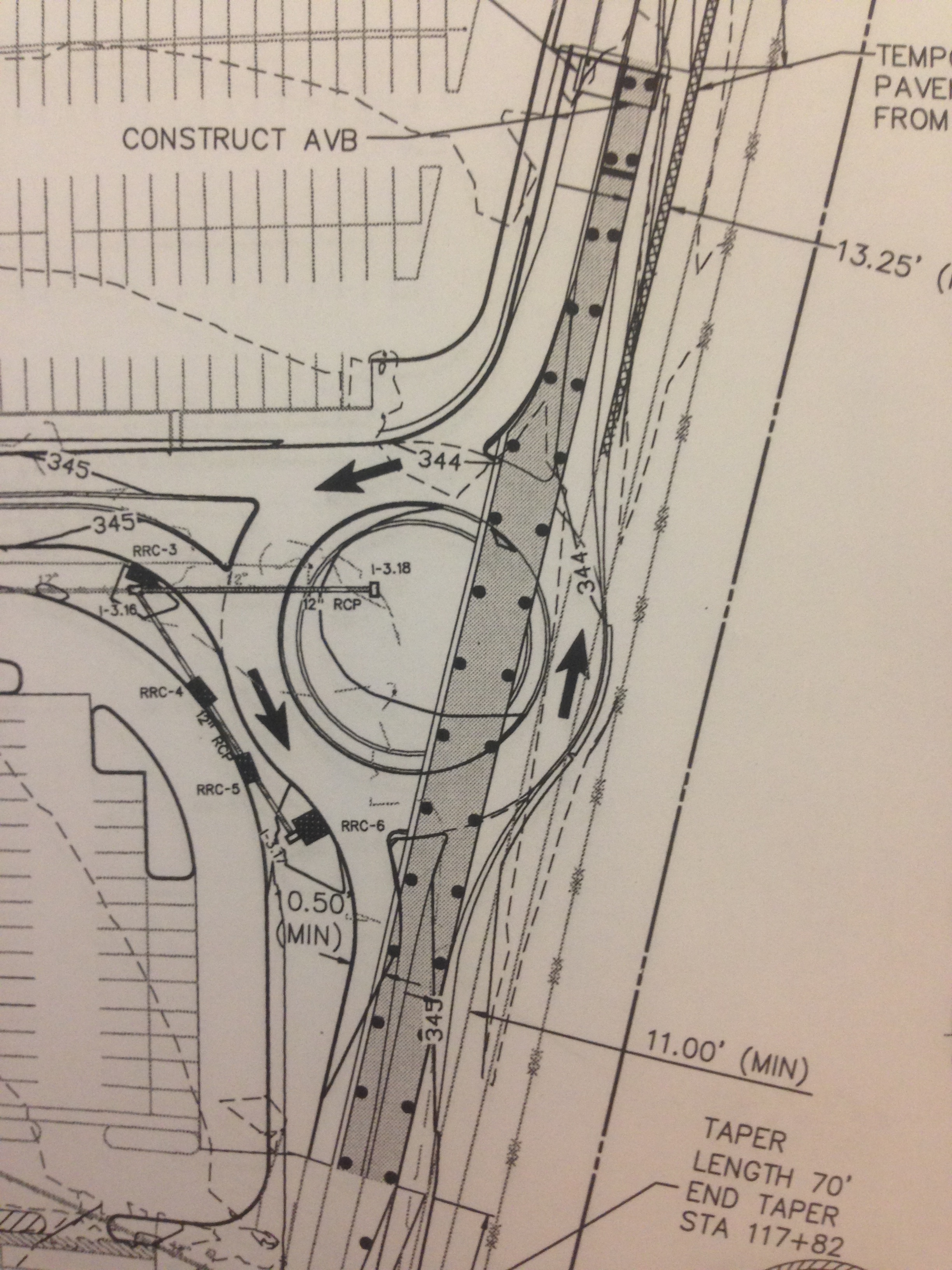
Phase 3 – This will be a safety concern for the workforce
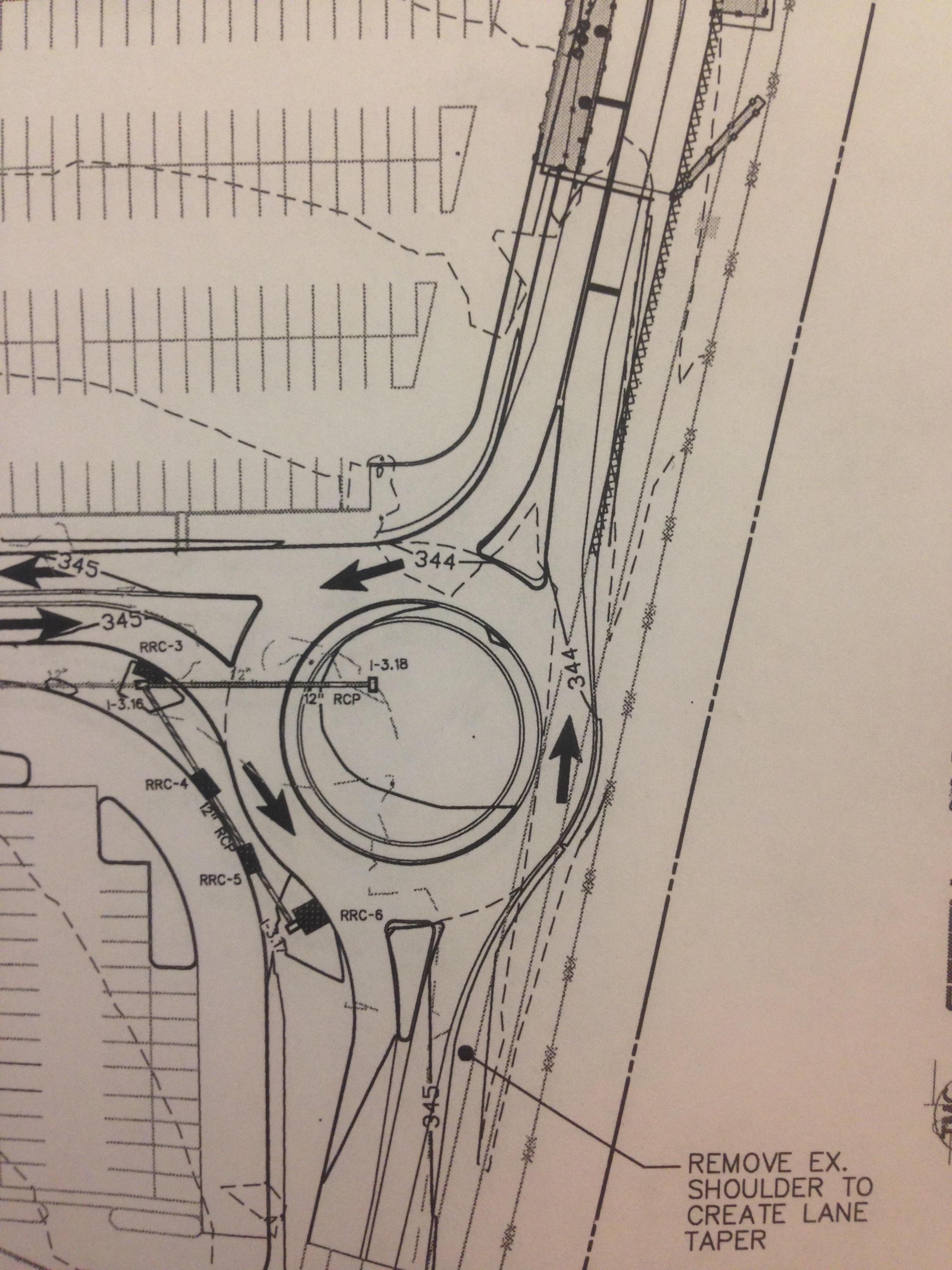
Complete
Finally, to follow on from Damo’s post about cyclist safety:
It doesn’t sound like it will happen any time soon, however it could have huge implications for construction within whatever zone it was implemented. Damo, has the cycle safety scheme on your site been well received?
How many wrongs make a right?
My first TMR focussed on what the project team assessed to be the greatest financial risk on the project – the rate of tunnelling. The head contract stated we were to be granted access to site 18 August 2015. The client gave us early access and so we began with surveying, fencing the alignment (7.8kms) and setting up the main office compound, and ting.
Early access to site = early finish and more profit? Or do ‘fools rush in’? The team is not yet fully staffed so every man and woman is doing everything. Amidst the chaos of shoving the entire team into a single portacabin running off a generator, and a wireless network that spanks in every 15 minutes, we are painstakingly making progress in getting ‘things’ to happen.
This leads me onto the point of this blog.
I have spent the lions share (not Cecil who was killed by the trigger happy yank – Brad?) of my time compiling tender packages for subcontractors and materials suppliers. This is followed by tender analysis and then recommendation prior to contract award. Materials such as steel reinforcement can be procured through a PO (purchase order). Having a contract in place saves us the hassle of shopping elsewhere at a later date as it prohibits the supplier from raising his prices midway through the project. It also makes forecasting simpler.
If a ‘grubby subbie’ as the team refers to them is going to provide any labour on site, they are obliged to meet the building code of compliance. This eliminates sham contractors (cowboys) who don’t have their own workforce and attempt to sell the job on for profit after having done absolutely squat. To meet the code of compliance, these smaller companies are required to pay into their employees’ Supa (pension) amongst other things. Proving they are compliant is a lengthy process, taking John Holland about a week to check.
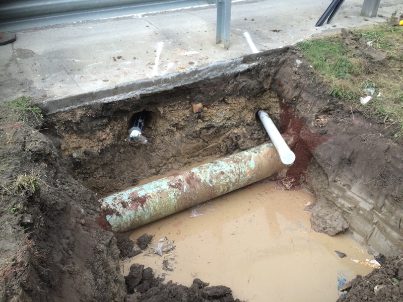
The client (YVW – Yarra Valley Water) is obliged to provide us with a water supply for the project. We have sneakily asked them to place it where they would bear the cost of getting it across a busy road. YVW engaged a local sub-contractor called Select Solutions to carry out the works (directional drilling under the road from a launch pit to a receive pit). My Traffic Management Plan was approved by VicRoads on condition that we would not cut the road to run a conduit for a return waste water pipe. The output – we needed to bore under the road for a return pipe to a temporary sewer.
The risk? Electricity, gas and fibre optics. The plan? Select Solutions, and hence YVW, owned the risk of finding a clear reach under the road. So yesterday I engaged with Select Solutions directly to see if they could do another bore for us, parallel to the supply line i.e. proven route. They were happy to, at a third of the cost of the next best quote I received. His only concern was the timeframe to receive payment when dealing with Tier 1 companies.
The issue? One day is not enough time to verify code of compliance. And the job could not be done off a purchase order due to the labour element. So this was a missed opportunity as a later date would see us incur mobilisation costs which YVW had absorbed for this particular window.
This morning I attended a lift planning course in head office. While I was away, the team just got them to do the work with a ‘promise’ we’d pay them (!), and without proof of compliance and insurance. One could argue that YVW wouldn’t employ a sham contractor, but that’s not the paperwork umbrella JHG requires. In the end the job went ahead without incident and we have a return line, but the consequences of hitting the fibre optic, gas or electricity would have dwarfed the small victory. Cut a handful of fibre optic cables and all of a sudden the rate of tunnelling might not be the biggest money pit.
If that wasn’t enough, VicRoads specified the bore had to be 1.2m below the pavement surface as they will be doing roadworks there in the next few weeks. See the photo, that’s not 1.2m! So what do we do? Backfill and pray VicRoads don’t come sniffing.
Now Select Solutions just need to monitor their bank statements…
Spec? What spec?
CPD/ UK Spec Attainment – Science, Technology, Engineering and Mathematics Network (STEM)
CPD/ UK Spec Attainment – Science, Technology, Engineering and Mathematics Network (STEM)
A way of achieving ICE attribute 9 – Professional Commitment, is to promote engineering (sub-attribute 9D “Demonstration of appropriate professional standards, recognising obligations to society, the profession and the environment”. I suspect the IMechE and IET have a similar requirement under the UK Spec.
One way of doing this is to use the Science, technology, engineering and mathematics (STEM) network.
This is a nationwide charity which has links to schools and groups for STEM Ambassadors to visit and talk about all things STEM (or specifically engineering in our case). The process involves getting a Disclosure and Barring Service certificate (newly named CBR check to be able to work with under 18s) and attending a 2hr induction. I am blogging because I have just attended an induction which was pretty useful because my baseline knowledge was low. I have included a brief summary of some of the points for those thinking this might be an interesting route to take…
There are 4 principles to adhere to for a STEM activity:
- There must be benefit to students
- The subject delivered must be STEM based
- Non-supervisory
- Voluntary
The STEM network has a database which works two ways. If you have something to offer schools you can highlight your skill and teachers will respond. Alternatively, teachers will request ambassadors to visit and deliver a talk/activity/lesson.
The ICE has lots of resources to assist and there are case studies which can be used for inspiration for lessons.
A constant theme was understanding why you want to be a STEM Ambassador – most people either said to promote their subject to inspire young people or to get more women into the subject. Otherwise the general position was that people were enjoying working in a STEM area and were keen to pass on their enthusiasm to a younger generation.
Thoughts
This approach (using STEMNET) is not the most original and I was not the only student in the room there to demonstrate ability of an ICE attribute, but actually it looks like a very sound way of promoting engineering to young people. That is something I felt my school did less well so it is interesting (to me at least) there are now even after school engineering clubs!
The audience was perhaps the most diverse I have ever seen: old, young, male female, mixed religions, races, languages, you name it. The spectrum of people being inducted as STEM Ambassadors was so varied (head of IBM equality and diversity to a student who wanted to promote how to make computer games) that aspect alone provided interest in itself. That is part of STEMNET’s approach to breaking down stereotypes – refreshing.
In a growing industry, at least while the economy is on the rise, it seems an ideal time to promote engineering to young people.
https://db.stemnet.org.uk/register
Site Two Fifty One – Prop Installation
Site Two Fifty One – Prop Installation
Despite site activities being focused on the remaining piling works (17 CFA piles to go), as always there is a push to do multiple other activities all at the same time, but luckily not quite in the same place.
Groundforce Shorco prop installation. The aim is simple – put in 9 props and remove about 1500m3 of water and about 10,000m3 of sand and gravels (and some clay).
Prior to now sections of capping beam have been poured, shear stubs were embedded and prop end plates were fastened.
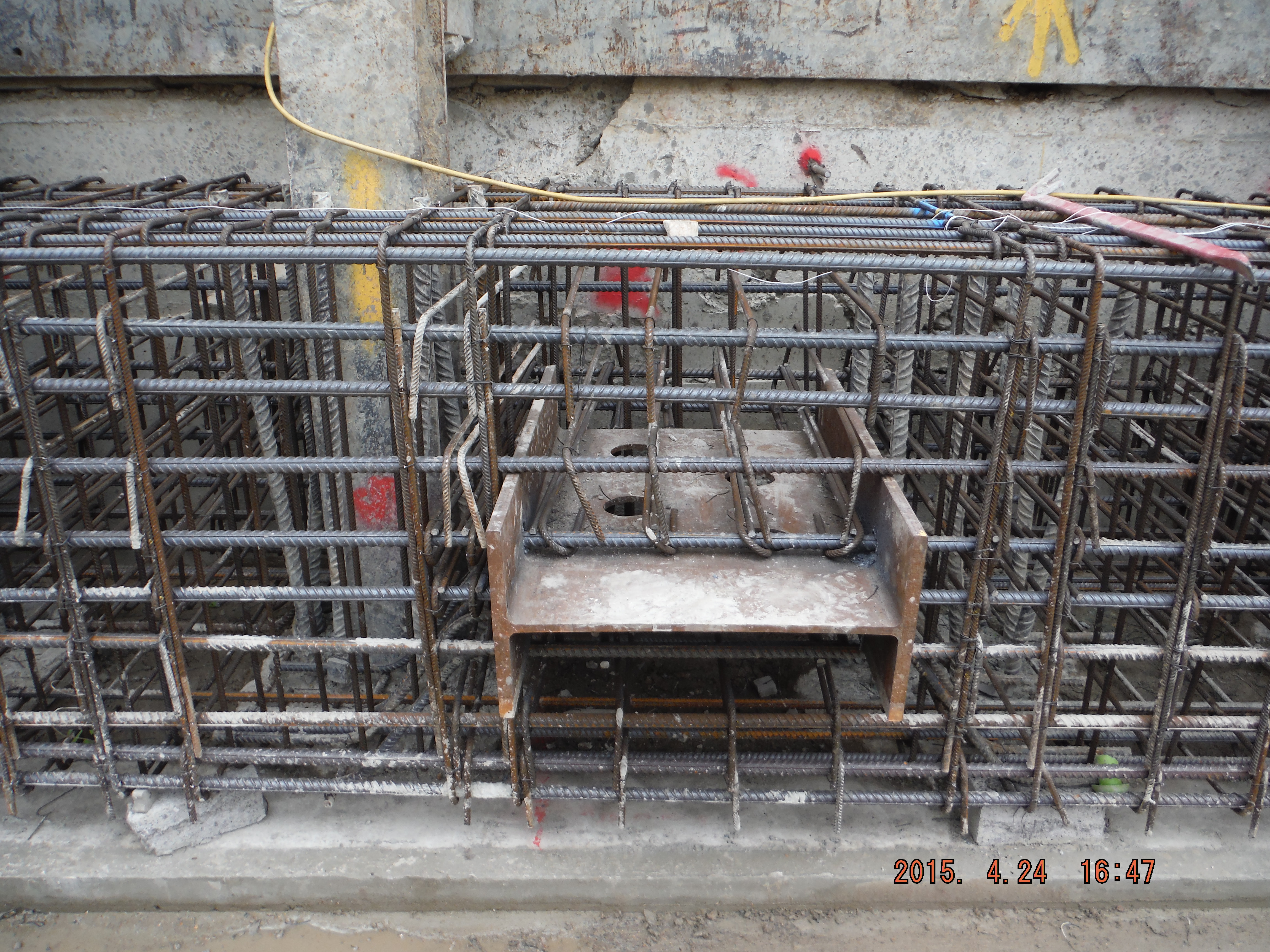
Shear stubs installed
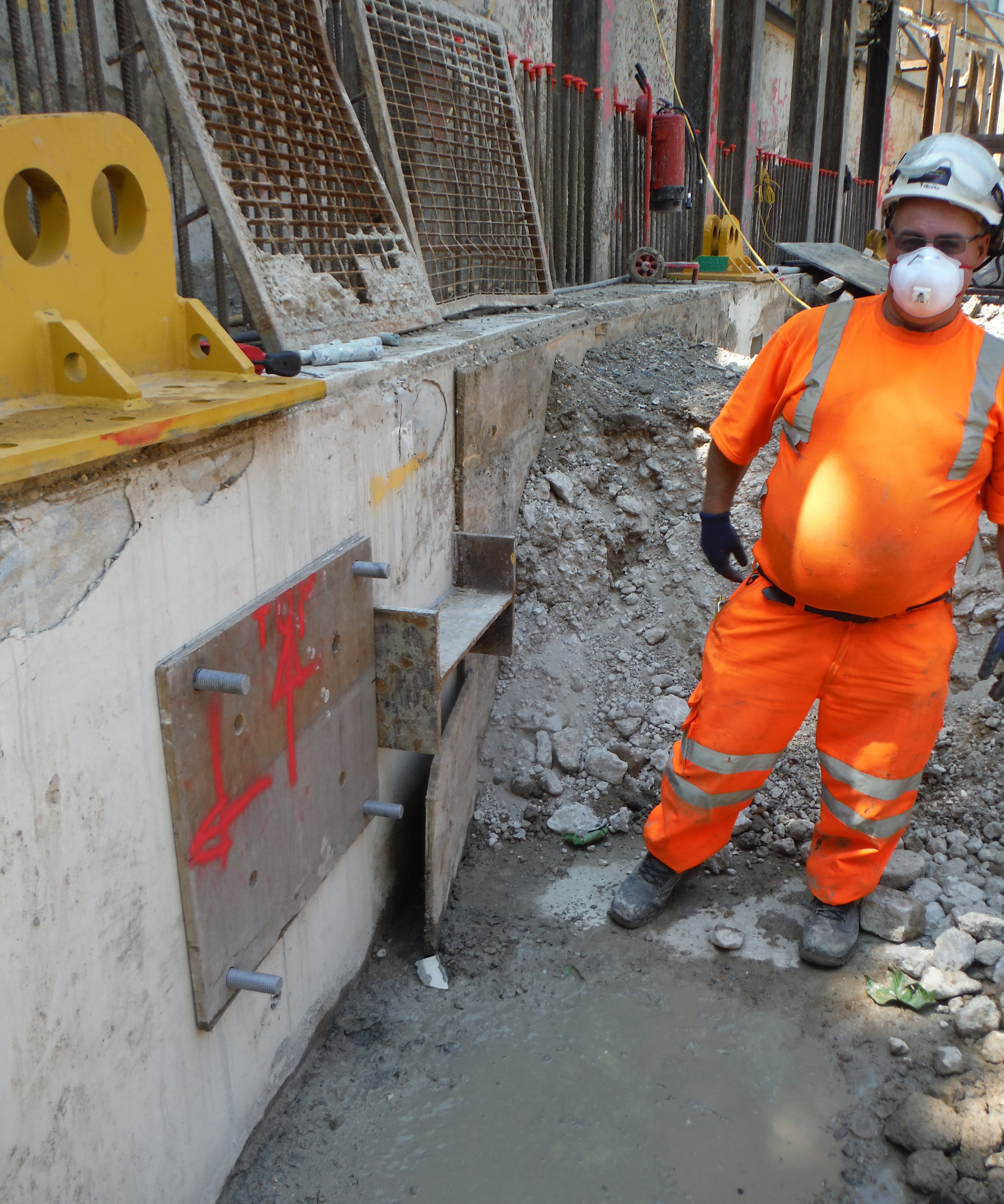
End plates being fastened to the capping beam
The general principle is to excavate to underside of capping beam, install a prop, excavate in order to dewater, excavate more, dewater more, install the next prop and repeat, 9 times (9 props), all while avoiding piles and segregating the exceptionally beach like sand and gravels (removal of this is less than half the cost of clay muck).
The first 2 props were installed this week and aside from problems with crane time there are a few other interesting points to consider.
Problem 1. End plates not meeting with shear stubs. Despite very careful installation of the 4 x M30 bolts embedded 250mm into the beam using resin, the end plates did not quite have full contact with the shear stubs. Options: weld a connection, use a grout pack, place shims or do nothing (assuming with the applied prop pre-stress the gap would close) to provide a load path. A good weld is difficult to achieve in a 30mm deep recess and the plates may well be damaged when the weld is ground off at the end of the works. Using a grout pack is possible but with movement of the prop (thermal expansion in the day) this might crack. Shims – the best and simplest option – this was chosen and on referral to the designer, the recommendation was to use S275 steel.
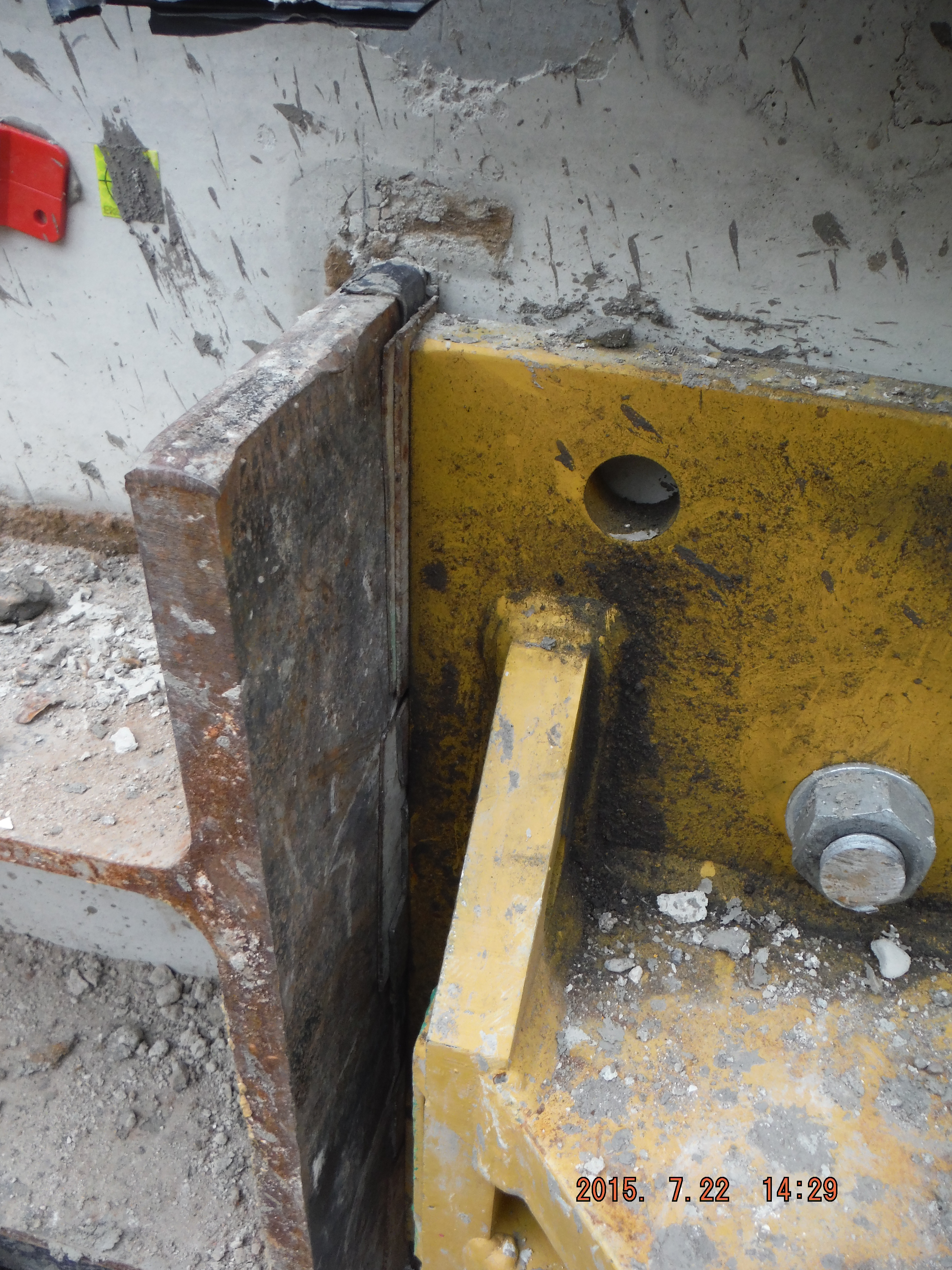
Shims used to provide path for load transfer
Problem 2. Not all of the capping beam is complete. The capping beam (which will form an entire ring around site) is used to transfer vertical load (from the buildings above) to the piles below. It is also being used to prop against horizontally.
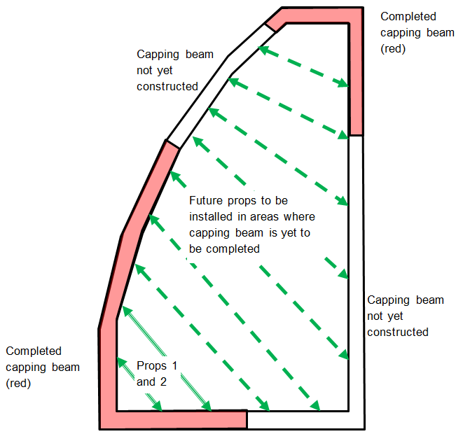
Diagram shows line of completed capping beam (in red) with future props to be installed (dashed green arrows) in areas of capping beam yet to be cast.
The question is, is lateral load transferred along it (as if it were a steel beam) to the ground at the corners or to the secant piles below acting in a sort of individual cantilever/domino fashion. The secant piles have 900mm of reinforcement cage embedded into the beam and are at 1.2 centres with male C30/40 piles and alternate C10/15 female piles. On further consideration, the female piles are only there to provide water resistance, so the load is transferred into the top of each pile down into the ground (embedment anything up to 23m for the permanent condition).
This can be modelled as follows:
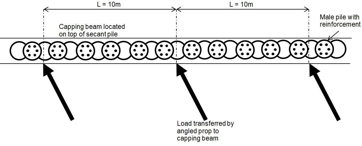
Plan view of capping beam showing prop loads applied to beam
By splitting the capping beam into sections around the props (10m spacing between props in this case) each pile within the section can be considered to carry part of the prop load. It is proposed the nearest two piles will see more load than the next two and so on. If each prop and pile section behave in this way it implies that as long as the capping beam is completed to at least midway between the next prop the system should work. That’s the theory anyway!

Plan view showing prop load transferred horizontally and vertically into the capping beam and onto the male pile reinforcement

Props 1 and 2 in place
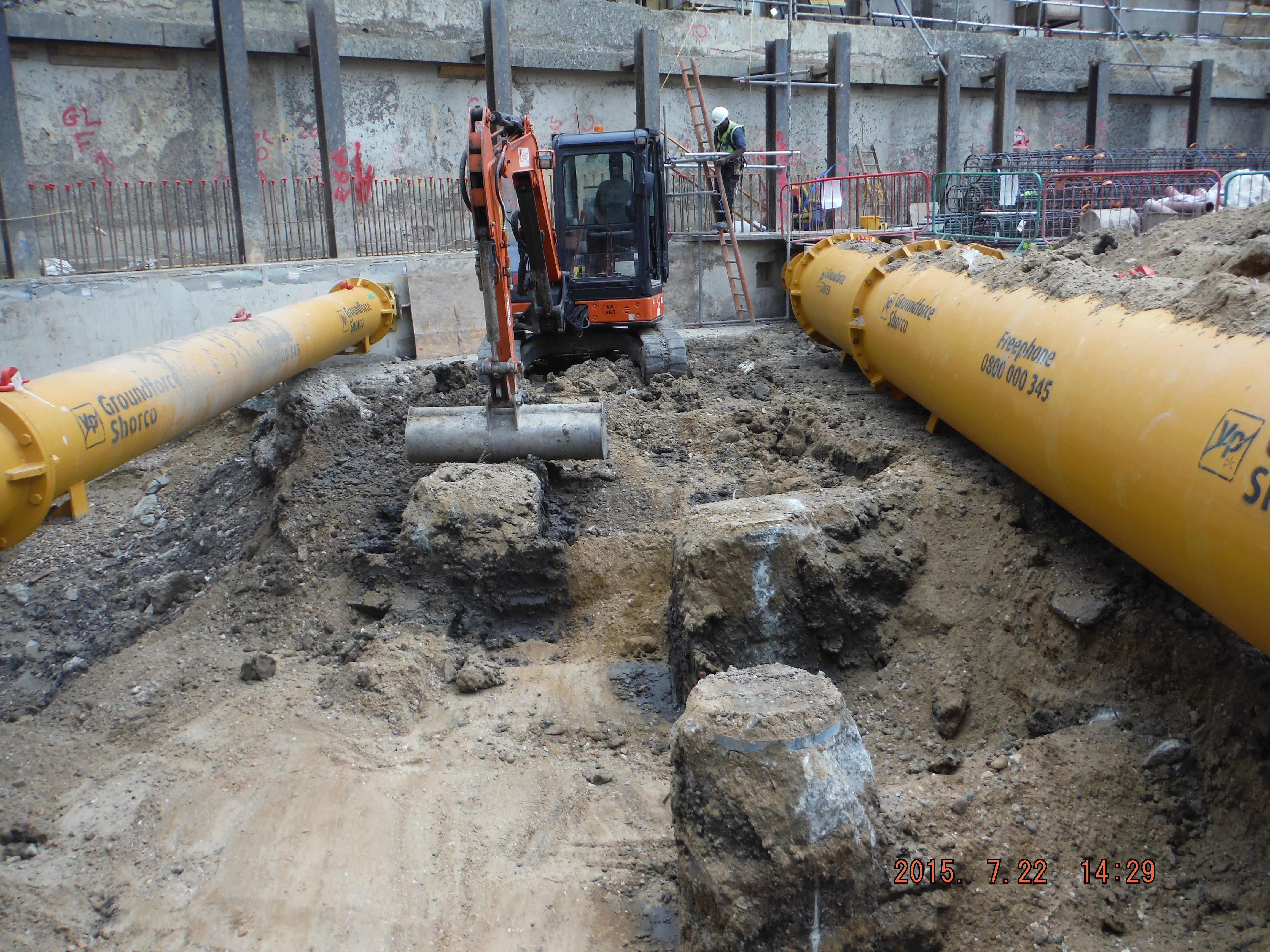
Excavation between bearing piles
Problem 3. Remaining props are likely to be installed prior to the capping beam reaching 50N/mm2. Similar situation to above, capping beam is designed for permanent loading, temporary design is for 30N/mm2. Looking at the cube results, this strength is reached between 15-25 days. Therefore, in theory, this is when the props can be loaded. To be more sure additional cubes will be cast and crushed to understand the rate of strength gain between 7 and 28 days a little better. Additionally the plan is to use thermocouples within the beam to understand the actual temperature of the concrete. This could then be replicated in the curing tank and rather than adhering to the 20 degrees standard, which should produce more realistic cube strengths similar to actual conditions.
Contract Update: Work on site is currently progressing at risk (no formal contract) – the monthly instructions to continue work ran until 20 Jul 15 and the next one (as far as 20 Aug 15) has not yet been signed off. The client has hand shaken on the main contract with Ray O’Rourke at £119M so clearly all will be fine!
Handy – from Phase 1
I thought I would post a quick note to mention something from Ph1 that I have continually found to be useful, from a civils point of view obviously. Quite a lot of my time on site is centered on rebar drawings, which can seem fairly impenetrable. Although it was only around a days worth of taught time in Ph1, and incorporated into a design exercise, the lesson on reinforcement detailing has continually proved invaluable in allowing me to add some value and hence afforded me some credibility on site. Don’t get me wrong, I haven’t had to DO any detailing (yet), but understanding how I could means that I can read the drawings and conduct checks.
Multiple Drawings
Following on from that I picked up an error in some rc walls the other day which are going to house some utilities. The rc chambers are being built to hold pumps and ‘stuff’ which will tie into main water tanks (chilled and non potable). The water tanks are steel and are off the shelf, arriving at the CUP at a later date. What’s interesting, in inverted commas, about the error is why I picked it up. I was using shop drawings, for which no contract drawings exist as the tanks were not part of the original design work. (There is simply a bit in the specs saying that there are tanks required and that the Principal Contractor (PC) is responsible for sourcing them.) The PC was using an updated set of field drawings. These are typically slightly different to the contract drawings in as much as they account for the amount of steel that is going into whatever feature of work it is they are for. A cut from the drawings I was using are below, with the offending bar highlighted in red.
Excerpt from PC Shop Drawings
That bar, is a 5/8” diameter. (annotated ‘#5’) bar which should go on each corner, as you can see in wall W-02, with the remaining bars being number 4’s (#4) which are ½” diameter. On site #4s had been used all the way across. I was able to ascertain that the #5s hadn’t been called out on the field drawings, which is an error on the part of whoever produced those drawings. So the error arose, and was caught by the fact that multiple versions of the same drawings existed. If we had both had the most up to date drawings the error may have slipped by. I guess the lessons here are try to always obtain the most up to date drawings, and ensure that they are correct! This brings me onto another point…
RFI Tracking
… How does everyone else keep track of the RFI’s and various changes that occur to the contract drawings? When I go out and conduct checks I always take the contract drawings and the field set. Before I go out though I have to print out the relevant contract drawing and highlight the RFIs and amendments to it in pen, using a hardcopy set of drawings onto which all RFIs and amendments are noted as they come in. A picture of what on earth I am talking about is below.
Mandraulic Updates on Conformed Contract Drawings
This is a drawing from one of my last checks. In pen are the RFI numbers and where they relate to. (ignore the bits in black, they are notes from the inspection itself) Before I go out I have to read what the RFI was and what the amendment is. Fairly laborious. Now, the pc who is clearly doing fairly well for itself has deigned it more productive to supply all its engineers with iPhones and iPads, with indestructible cases. They are all therefore able to download any drawing whilst on site. All their field drawings are updated by CAD Wallahs and replace old copies as RFI changes occur. Since the government doesn’t have CAD Wallahs its contract drawings don’t get the same treatment so we are stuck on the original conformed set, with ever increasing notes and cross references to RFI numbers.
Since everyone else is working for high flying engineering contractors I am curious, how do you do it?
LEED
As I suspected in my last blog the LEED issue has reared its head again. I sent back a submittal ‘E’ coded (re-show) for not having the required third party certification showing VOC levels. The pc called, stating that the manufacturer doesn’t have third party certification, nor is it willing to get it for one product on one job because it costs c. $30k. I suspect that the pc is less than enthused about paying either. From a government point of view and on reading through the specifications there is a very clear requirement for certification. As far as I am concerned it is the contractor’s responsibility to obtain the certificates, a point I will articulate. However, in the interest of not being a complete douche about the situation, and in the interest of maintaining positive relations I am currently investigating an ‘out’ for them. I know that any material that is installed out of LEED compliance can be ‘offset’ through focusing on the installation of super low VOC content material in the vicinity of the non-conforming material. What I am less clear on is whether this is for accidentally installed material, or as would be the case here deliberately placed material. I have sent the question to a LEED appointed person who sits with the client for their consideration. Another option I will table is the use of a different material altogether. The problem with this is that I have absolutely no input / exposure to the procurement process where I am at present. I don’t really know if this is a stupid recommendation but I will speak with someone at the pc end and ask, since we are currently on talking terms!
And finally
This is a picture from the historic Ft McHenry. It is where inspiration for the Star Spangled Banner comes from and is the site of an unsuccessful British attack. The bridge in the distance, which you can just about make out, is where the British Ships bombarded the fort from, retreating, presumably, when they got bored. The distance to the bridge was slightly further than the reach of the canons in the foreground, but just about the maximum range of the British canons.

Fort McHenry
I tabled the idea of a future OPD event to the newly arrived District Commander that we should do a battlefield study about how the Brits could do it better next time.
Levee Inspections
To attempt to take up the mantle from Howard of saving Pennsylvania from catastrophic flooding this week I have been out conducting inspections of elements of the levee network. Every year Baltimore District inspect half of the levees in their AO, which broadly covers Pennsylvania and a section of upstate New York and control flow into the precious Chesapeake.
Sadly my image of Hollywood style concrete channels where we could put the hire car to the test were dashed and replaced by oversized earth berms. I imagine this is the slow time equivalent version of the inspections carried out in six weeks by RE JNCOs in the UK last spring, except completed by two qualified Professional Civil engineers and a couple of hangers on like me.
Below shows a typical levee and our main tasks were to look out for ‘critter’ holes and the wrong type of vegetation. A common occurrence is for groundhogs to burrow completely through the levee, both allowing flow but also destabilising the remainder of the levee. Vegetation is important to promote soil stability but has to be able to bend to the flow to avoid creating an obstruction, or a place for obstructions to settle. Within the main straight channel to the bridge in the distance a meandering path has been engineered for the normal flow condition slowing the flow down, whilst allowing it to drain quickly in a flood condition.
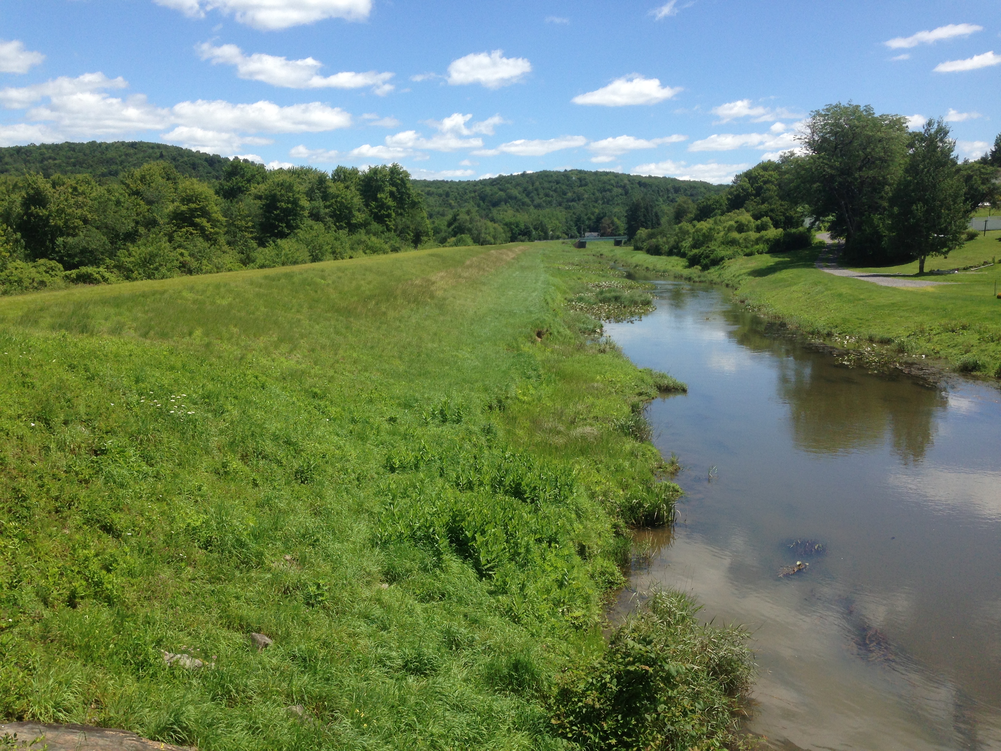
Typical levee and channel
To control flow through the levee from drains gated inlets are used and flap gates prevent back flow from the river up the pipes. These all required checking and had been greased to the standard a farmer would have been proud of.
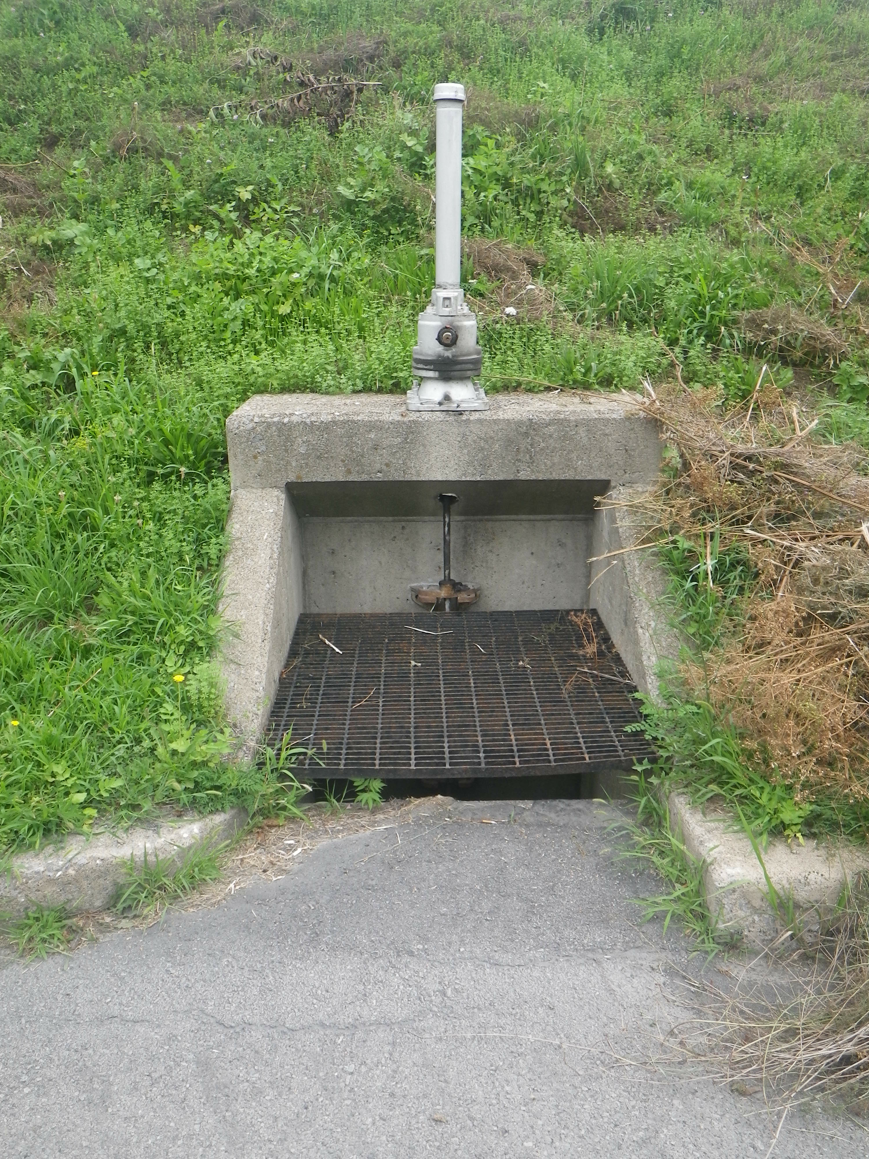
Drain and inlet
Flapgate outlet, minding out for snakes!
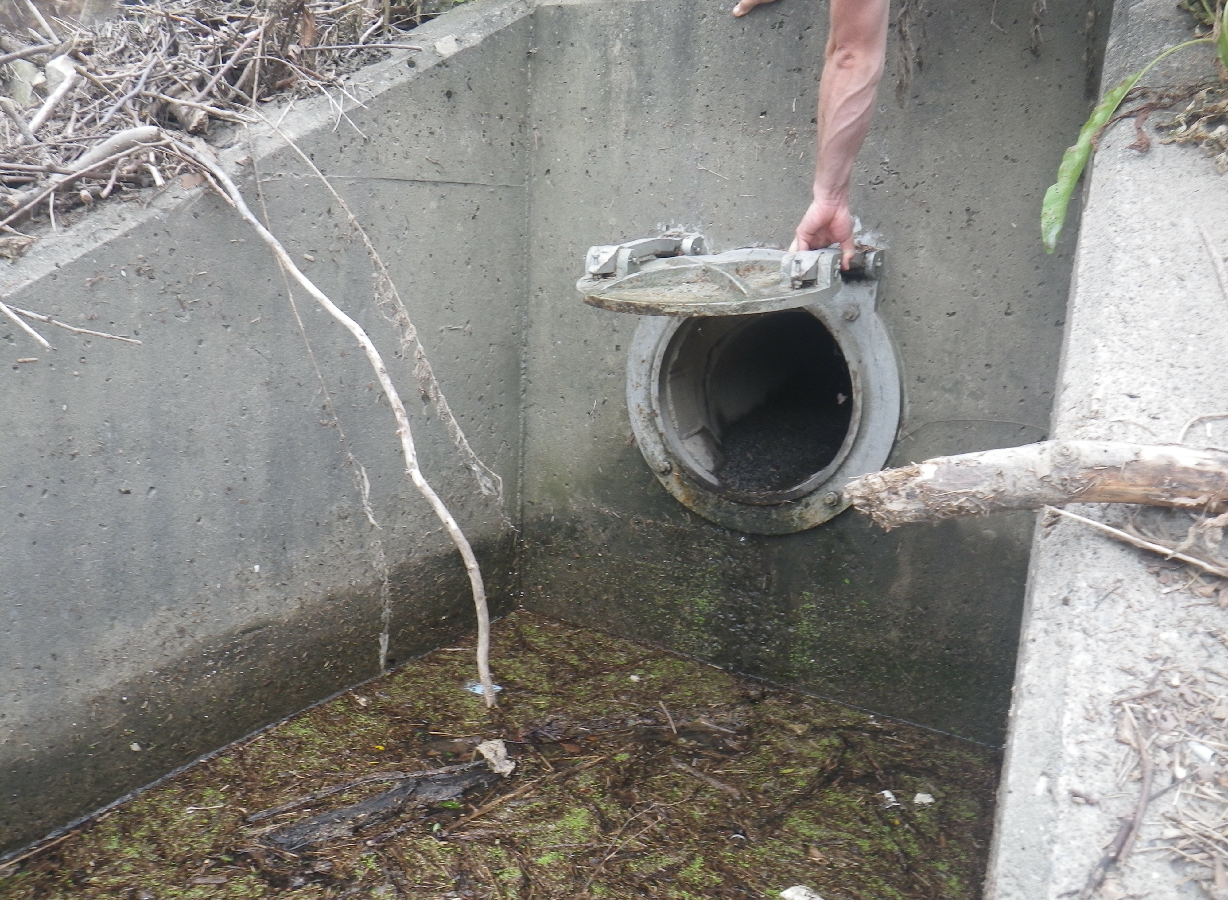
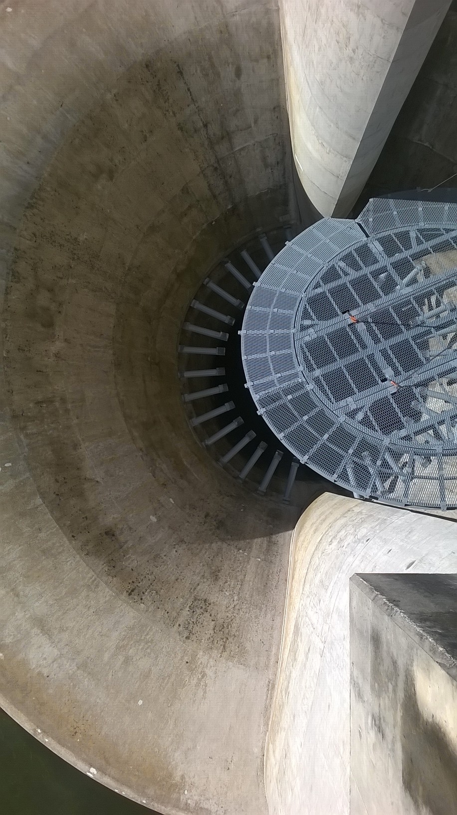
The systems we inspected were built from the 1940s onwards and were simple and robust in their design using, as one would hope, gravity where possible. There were a couple of pump stations with standby generators where gravity had to be overcome. As the drawing shows below a lot of effort is taken to remove the debris and sediment from the flood water to protect the pump and prevent it clogging the pipe work (or pressure conduit to use the vernacular).

Pump station
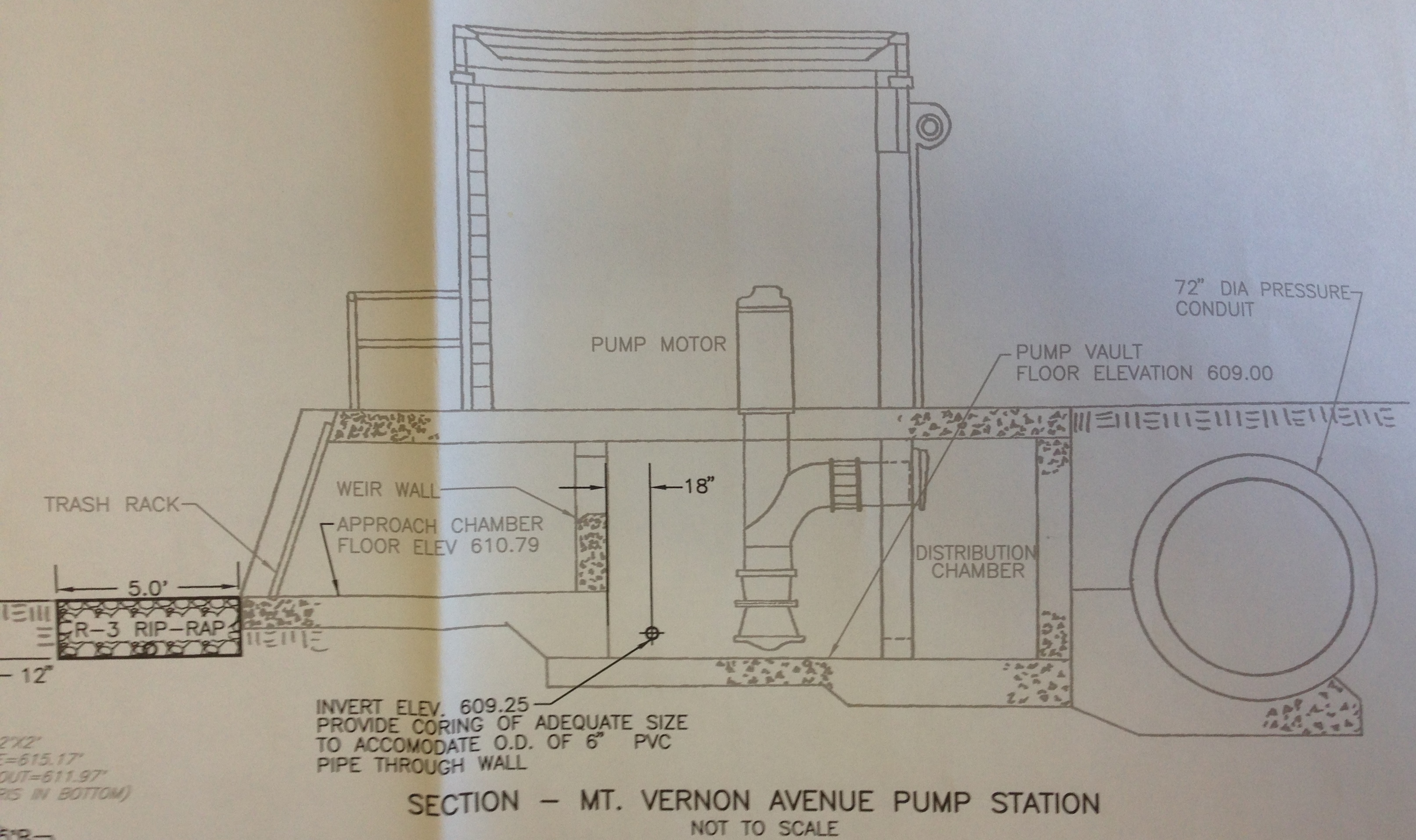
Section through pump station. Water flows L – R
Rip-rap is 6” diameter rough stone.
As far as analysis goes the question in my head this week has been how does it all integrate? My conclusion is that it doesn’t. Responsibility for each levee has been pushed down to the lowest level of government, the Township, and so there doesn’t appear to be an appetite for integration from one to the next. That said, as the map below shows, there is quite a lot of space between townships out here and so maybe that doesn’t matter.

Upstate in Pennsylvania. Huntingdon is 2 hours NW of Harrisburg
I imagine further down stream towards the coast where the population density is higher and all the water converges this would be more of a problem. For now I am going to shelve these thoughts and pick them up again when I get to phase 3, where I can speak to the hydro engineers in their natural environment.
Finally, for the civils who were whinging about making a cofferdam, this is how you do it ‘redneck style!’

Simples!
And apparently this is a salad…

You can just see a piece of salad poking out under the chips and cheese
All this paperwork is great, but who’s building the job…
This blog will focus on my exposure to the quality management system at Battersea Power Station Phase One.
To set the context of this blog I will provide a bit of an update on the project. It’s fair to say that the pace of life at Battersea power station is getting frenetic. Carillion (CCL) and Skanska Rashleigh Weatherfoil (SRW) finally got agreement on the MEP programme we’re working to, so pressure is naturally being applied to hit deadlines. This pressure is added to by the fact that CCL procured the job during the recession, under resourced it and have no immediate plans to increase the level of resources available. As I have previously mentioned the site has significant logistic constraints and complexity due to the sheer scale and profile of the job. Given these factors I would have thought it prudent to keep processes simple and not re-invent the wheel. This is certainly not the case with regards to our quality management system.
Battersea’s quality management system.
It will come as no surprise that the main way in which CCL are managing quality during the installation is through the use of Risk Assessment and Method Statements (RAMS) to ensure the planned method of installation is correct and safe. This is then followed by Benchmarks (part of the JCT contract) which must be the first of type on site to set the standard for the works including how it was achieved not just the finished product, Inspection and Test Plans (ITPs) and check sheets to ensure that the installation is being carried out as per the agreed specification, this information is then recorded in a package plan file which is the audit trail to the client that CCL have done their job. The processes I have just outlined seem straight forward and make sense to me. Where I believe Battersea is starting to over complicate things is through the overly zealous use of Benchmarks.
Benchmarks
Under the JCT contract that CCL have signed up to there are approximately 250 benchmarks that are required, none of which are MEP related. There are further 140 non-contractual benchmarks that have been created internally by CCL, the majority of which are attributed to the MEP team. Each benchmarks requires SRW to pull together an 8 page document with additional supporting evidence (details of the specification that the benchmark relates to, photos of the installation, relevant extracts from the RAMS and drawings). This paperwork then needs to be red penned by CCL, signed off by 5 people and utilised to inspect the benchmark itself on two separate occasions; quite a time consuming process in total for what is effectively a discretionary task. Due to the lack of resources on site these non-contractual benchmarks are not being closed out in a timely manner. As mentioned above the benchmarks are supposed to be the first of type on site. However, in reality by the time the paperwork is completed and the benchmark signed off the job has progressed far beyond the first of type being utilised as a benchmark. As an example, a recent benchmark for electrical containment took so long to close out that approximately 50% of the total installation had already been completed. In theory the works should have been stopped until the benchmark was signed off. But on a job that is already behind schedule that wasn’t going to happen. With regards to the specific example of the electrical containment, one of the reasons work wasn’t stopped was that everyone knew (from walking past it on a regular basis) that the work was being installed to a high standard. Therefore what was the point of this benchmark other than to tick a box on an excel spreadsheet? I believe the production of the associated paperwork took up valuable time that could have been better spent managing other areas of the job which would have resulted in improved quality. I have highlighted my concerns and they are shared by other members of the CCL team, however, we are being told to soldier on.
Entering the Morning Glory… but not quite as planned..
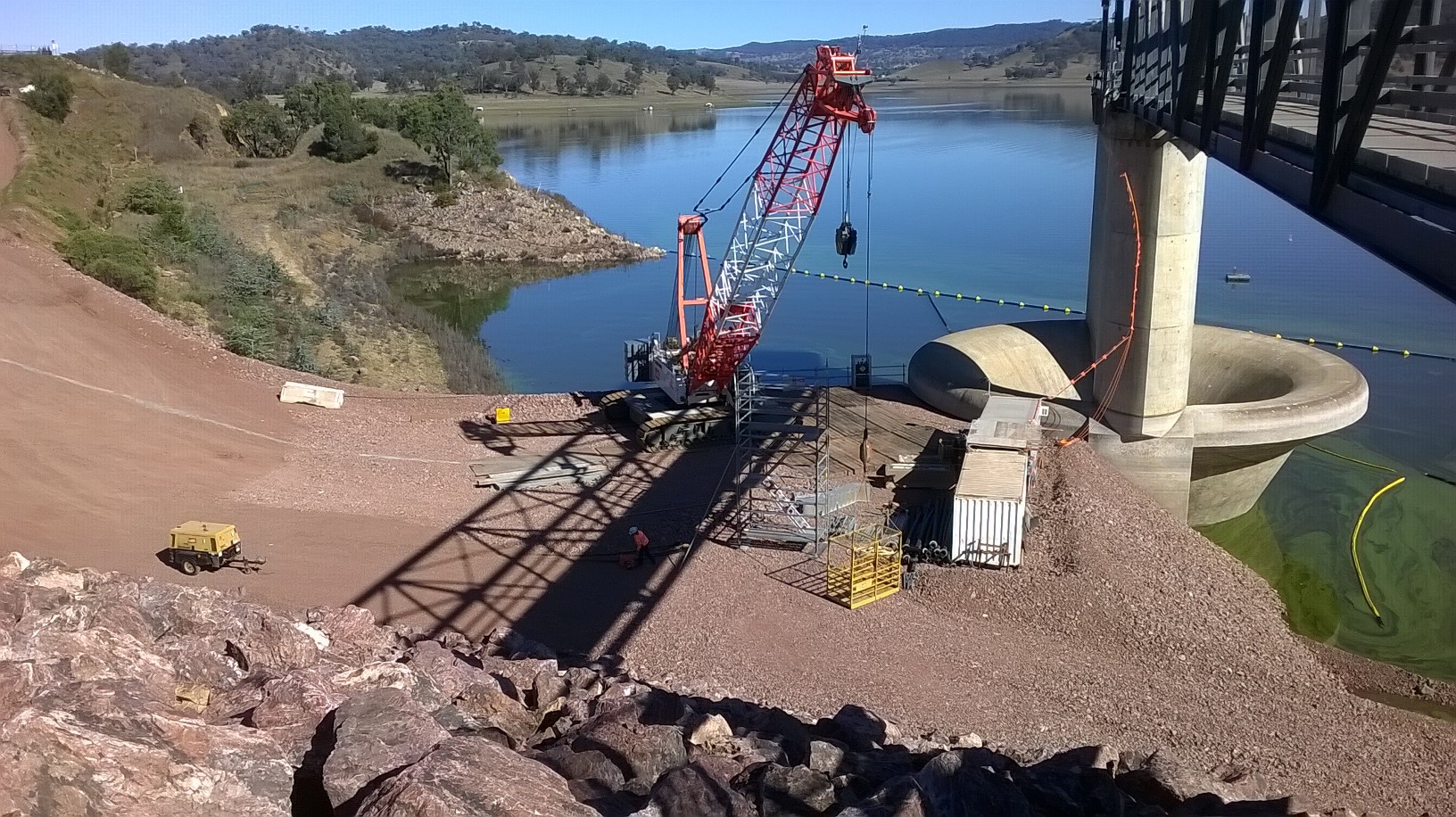
MGS Crane Mat on temporary gravity retaining wall.
1. Temporary Works Design (TWD). The decision was made to disregard the original temporary works design for raising the morning glory spillway (MGS) as it was assessed to be unsafe and impractical. As such, a full redesign was required despite the project being two months in. A highly regarded, Sydney based, designer specialling in TWD was approached for assistance in the urgent matter. Upon his acceptance, a “short form consultant services agreement” contract was established. The designer quoted a ten week period in which they would complete the full design. Seven months later and the design remains unfinished.
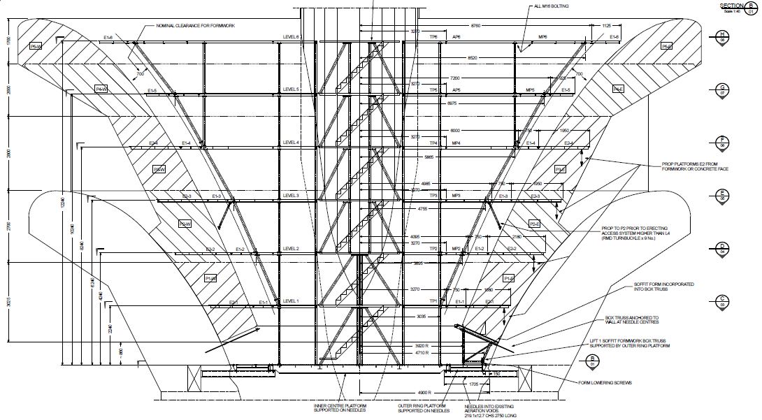
MGS Temporary Works Design
2. Several mitigation measures were implemented in order to account for the significant TWD delays:
a. Construction sequence. Initially, it was planned that the MGS temporary works access structure was to be fully operational prior to any works commencing within. Due to the TWD delays the decision was made that once the primary supporting system(needle beams and steel mesh base) was in place, scaffolding was to be erected to allow access within. The new method made it possible to beginning locating and marking all existing steel reinforcement prior and the time consuming process of core drilling (1034 holes x 45Ømm x 850mm deep.
Delicate Lift Operation – 160T Crane inserting the primary, temporary works mesh base onto 34 x steel circular hollow needles within the MGS.
b. Fragmentation of works. In the initial tender it was stated that the MGS temporary access was to be fabricated by a single company. In the interest of time, the decision was made to break down the works into smaller sub works packages that would then be put to tender on an individual basis. Although this measure would facilitate concurrency in production, it would expose the task to compatibility issues in regards to final construction of the temporary works.

c. The remote location of Tamworth also influenced this decision to fragment the temporary works. Local fabrication companies flat refused to makes an offer on the total temporary works access structure due to the required production time. This was because of their limited workforce size, real estate and production facilities.
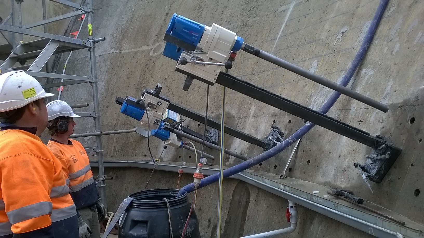
Core Drilling inside the MGS over improvised waste water guttering. Only 1032 x more holes to go…
3. Lessons Learnt.
a. Contract Details. The importance of a thoroughly considered and reviewed contract has been clearly demonstrated in this instance. Although a provisional timeline was provided by the Design Company within the Short Form agreement, it was stated that an extension may be required. Additionally, the Completion Date was strangely specified as “Project Completion”, effectively saying that it’ll be done, when it’s done. Consequently, there is no financial penalty for the designer although they have over-run by five months.

Water Testing in Chaffey Lake
b. Although the upgrade of Chaffey Dam is a State Water Project, funded by public money, John Holland are the private corporation delivering the project. As such, the federal requirement to go to tender on all on sub-contracts where public money is being spent, whilst good business practice, does not apply to John Holland. Following further investigation it was found that the design consultant selected is routinely employed by John Holland due to his impeccable track record and subject knowledge, despite the extended timelines!
Sundrop Farms Project Update
This blog aims to provide an update on site progress, as well as demonstrating the wide range of tasks that seem to land on your lap as an engineer. Apologies if it is a bit long, not had a lot of time recently to blog.
My main area of responsibility (the pipeline) is nearing completion, with the filling for the hydrostatic testing taking place as I type, should take around 3.8 days. My involvement in this has been limited to developing the test procedure alongside the subcontractor and client, as well as ensuring the relevant standards are followed and John Holland isolation procedures are adhered to. It did however give me the opportunity to wheel out some P=ƿgh action when the client asked why we were not going up to the full test pressure (answer – because the pressure gauges are not at the lowest point). Other areas I have recently taken on include the intake and outflow at both the sea and project end, as well as the lining of the lagoon structures and all the associated pipework.
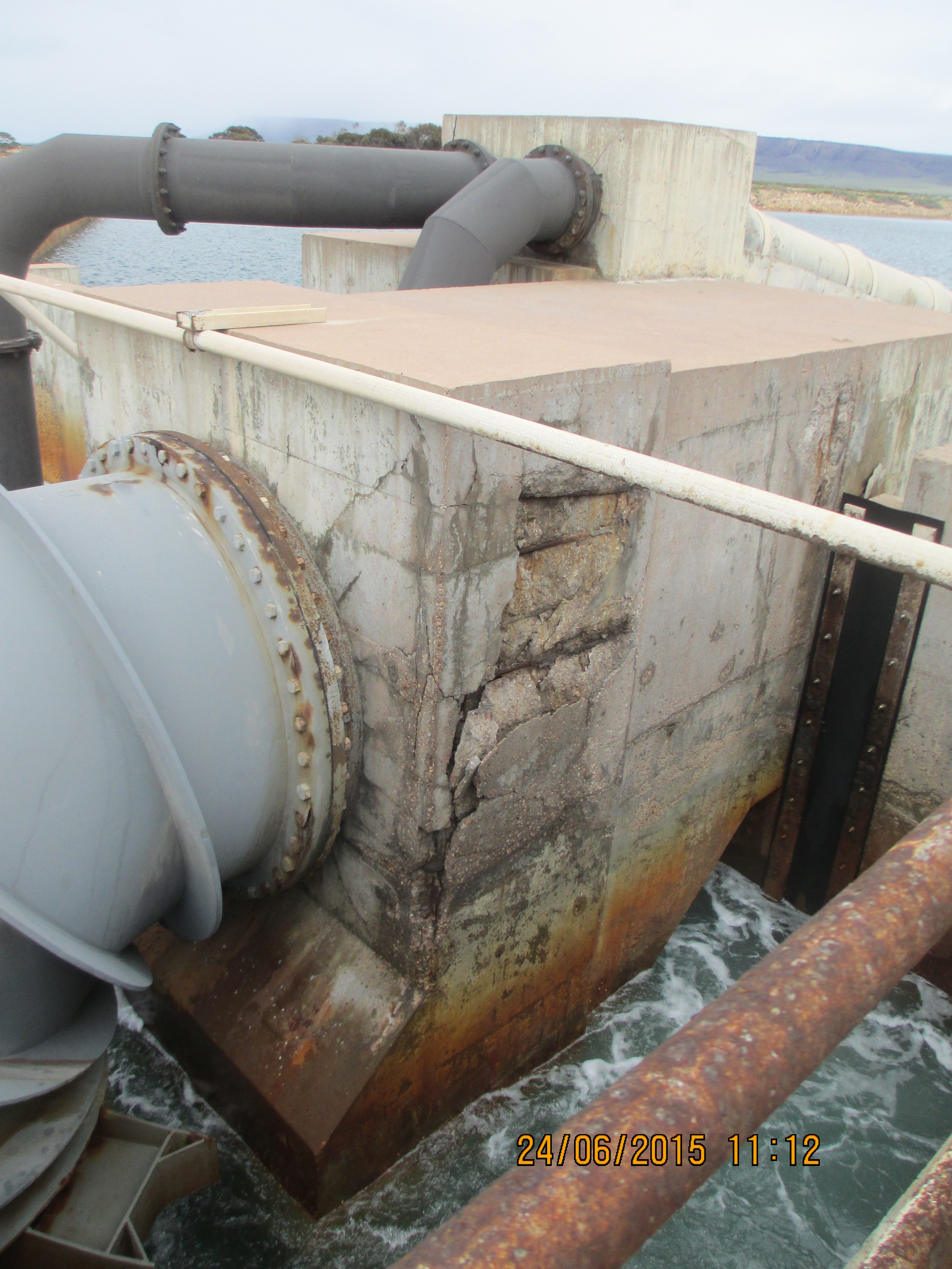
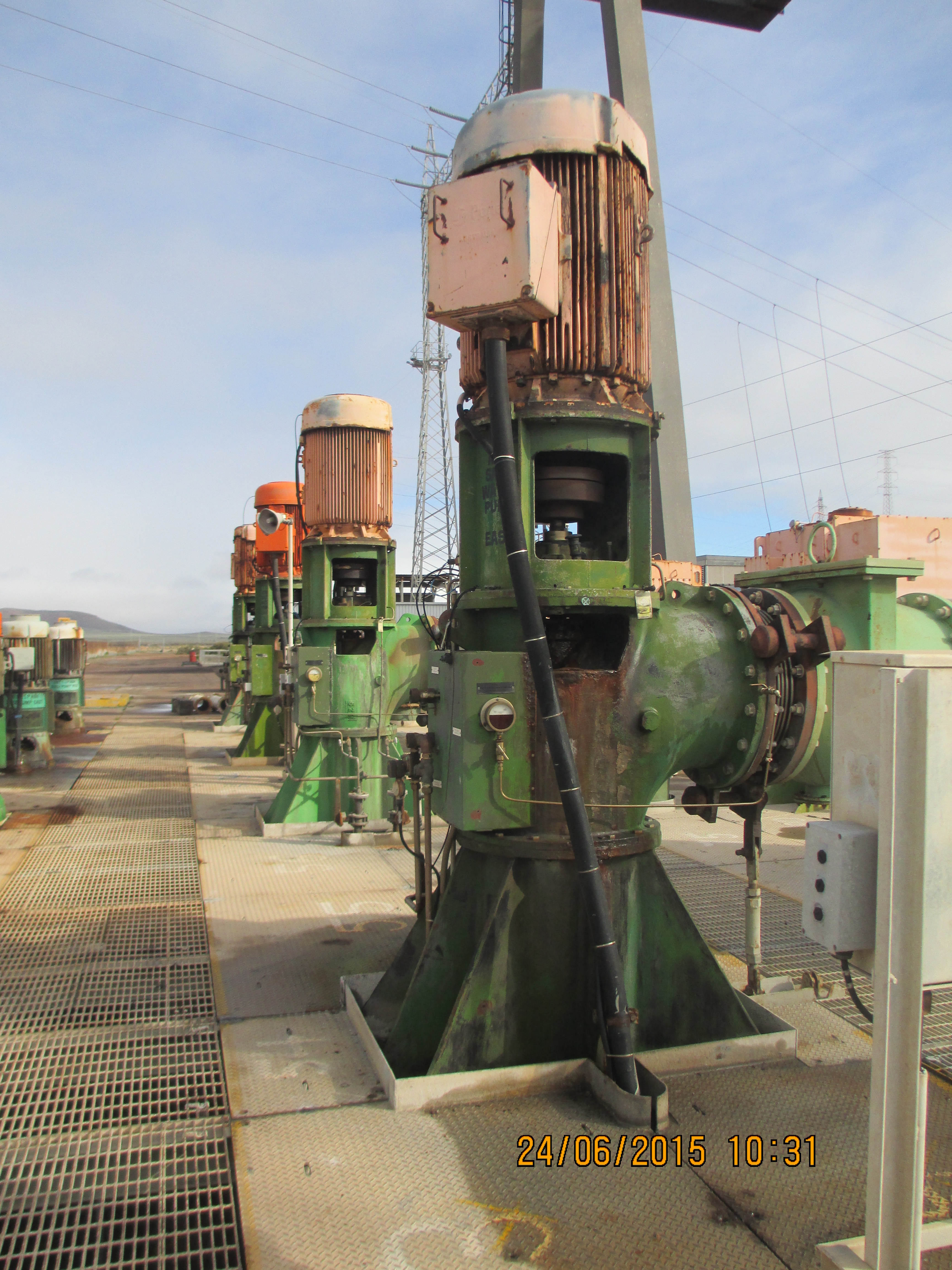
The intake and outflow for the pipeline at the sea end is a $1m package of work which has recently been awarded to Guidera O’Connor. I have been responsible for developing the scope of works, getting the designs to IFC stage, introducing the subcontractor to the project and on boarding their construction team. The design currently ties in with existing infrastructure at Alinta power station. A few weeks ago the power station announced its closure in 2016; previously this was due to be in 2030. This clearly has some major impacts on our project:
- Firstly the site is to be returned to the condition it was prior to the power station, including the inlet channel that we are building on and the control rooms that we were going to use for power. Currently this has been passed back to the Client to come up with a solution through negotiations with the land owner.
- Secondly the Environmental Protection Authority sign off for the brine discharge from our site was based on the outflow of the power station for diluting and mixing, prior to the water entering the sea. Further models are now in development by the University of New South Wales to analyse the impact.
A potential positive is the fact that the government is under pressure to do something about the number of unemployed persons in the area and as a result there are already discussions for a second Sundrop Farm project in the area, clearly this will be dependent on the commercial success of this one. At the moment we have been to soldier on with the current designs, with the hope that the Client comes through in the end otherwise we will have some major variations coming our way. I have included some photos of the existing infra structure firstly to show the state of disrepair that we are expected to link into and secondly to balance the fact that the remainder of this blog is civil based.

The contract for the lining of the ponds was awarded to Fabtech and was valued at $750,000 – at first I thought this would be a relatively pain free scope of work. After interrogating the drawings I discovered a whole can of worms in the form of buried services. Basically I have spent the last two weeks trying to find out who is responsible for what services, taking items out of various scopes of works and awarding variations to Fabtech in order to progress works as they are already onsite and we can’t afford any delays. In the process I have found gaps in both the design and procurement packages, which always makes you popular on site. One of the most surprising gaps at the moment is that there is still no plan for the waste water across the whole site, even though the subcontractor for buried services starts next week.
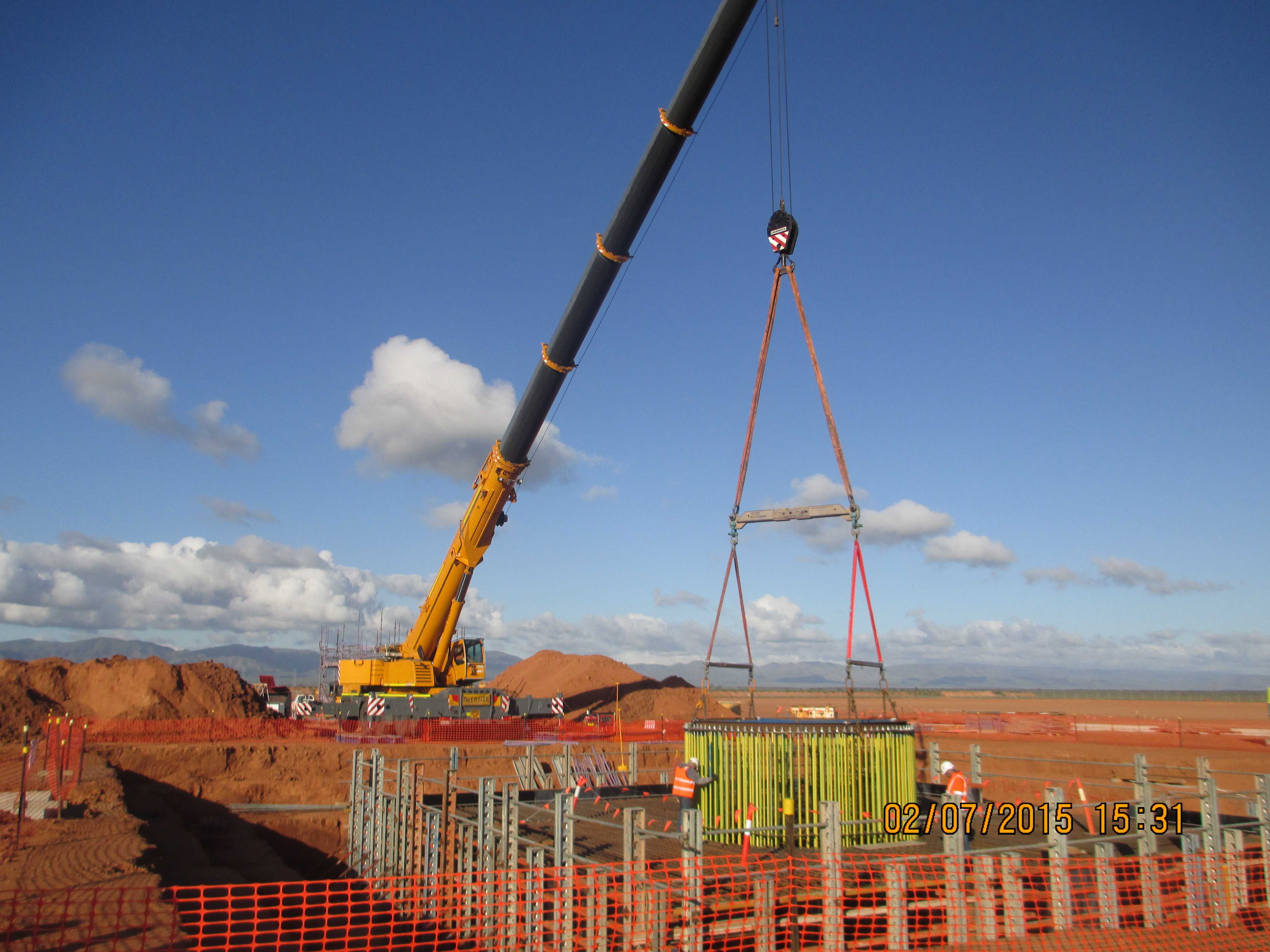
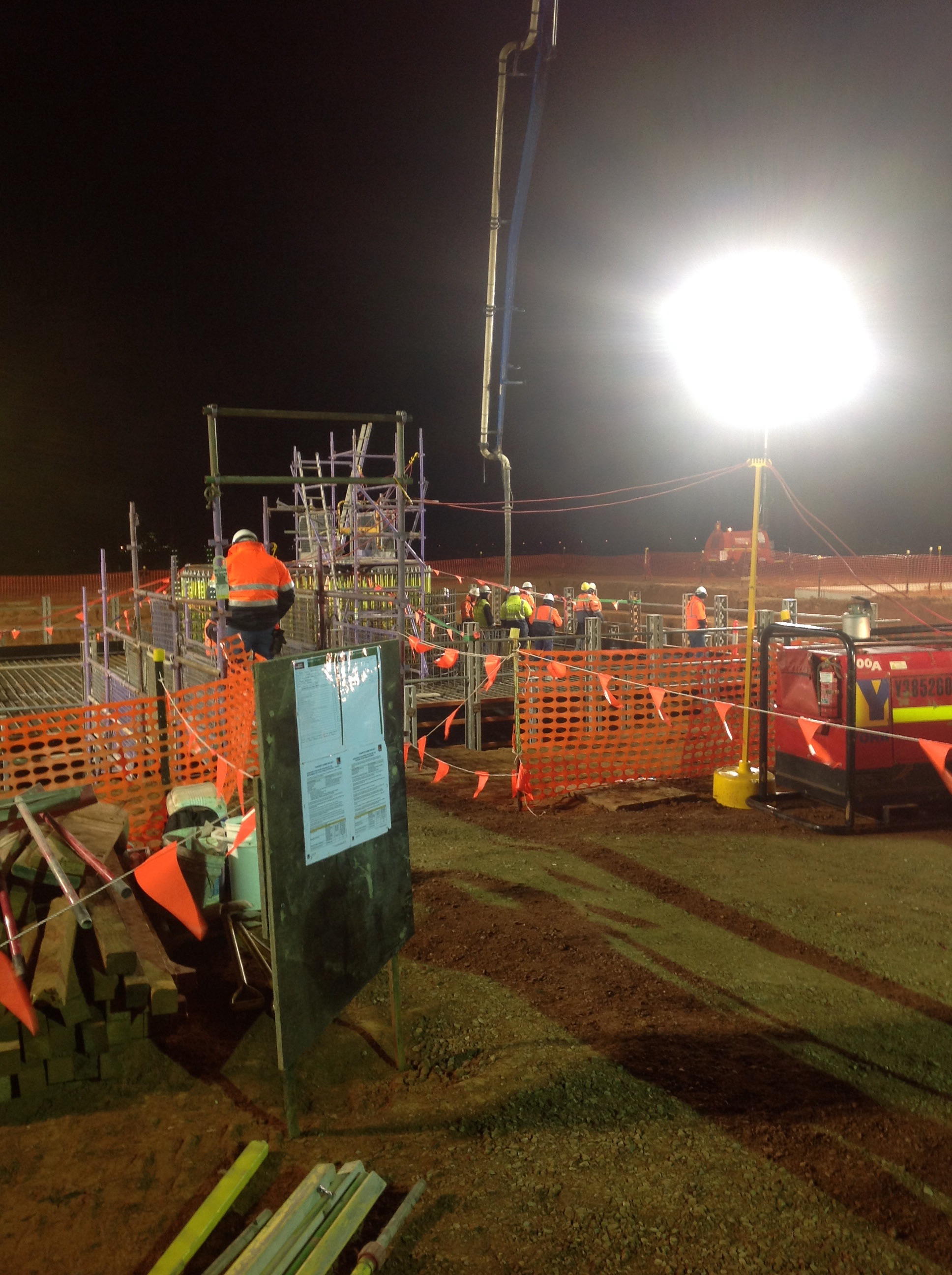
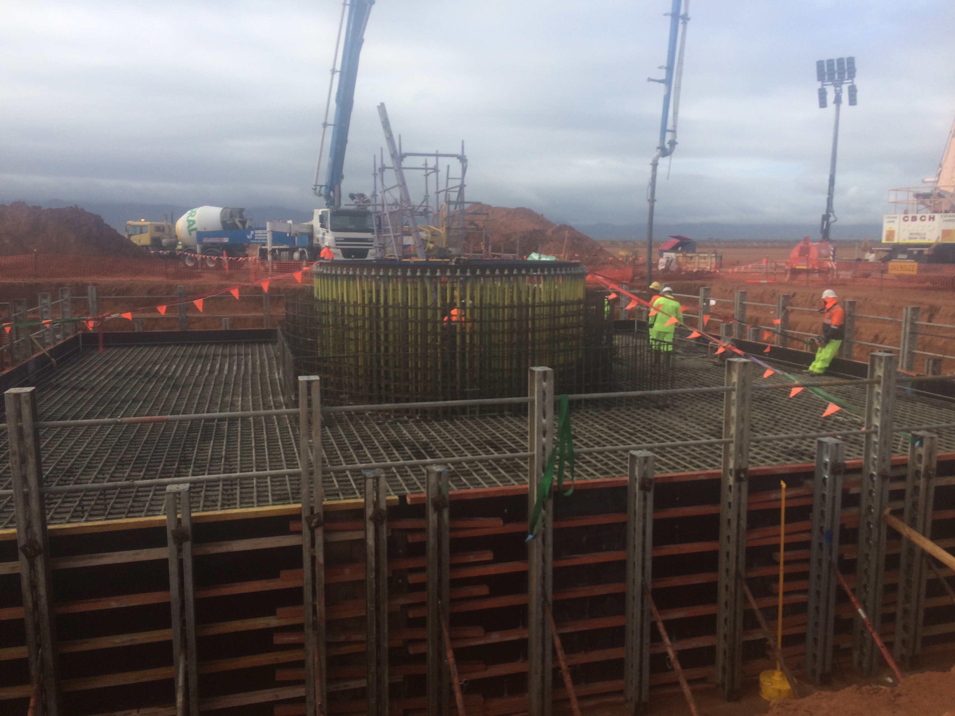
The big recent event on site was the pour of the Solar Tower foundations; I have included some pictures below for all the civil types out there. In total the pour was around 550mᵌ, it began at 0300hrs and lasted until 2000hrs. The planning and preparation involved in the whole pour was quite impressive and was greater than what I witnessed on some military operations, with standby pumps, plants and trucks identified across the state and put on reduced notice to move. Inside the reinforcement you can see the ring of 200 bolts, 4.5m long which will eventually hold the base of the tower. The photo’s below show the template holding the bolts getting lowered in to place, the start of the pour and the end of the pour (yes it is raining).
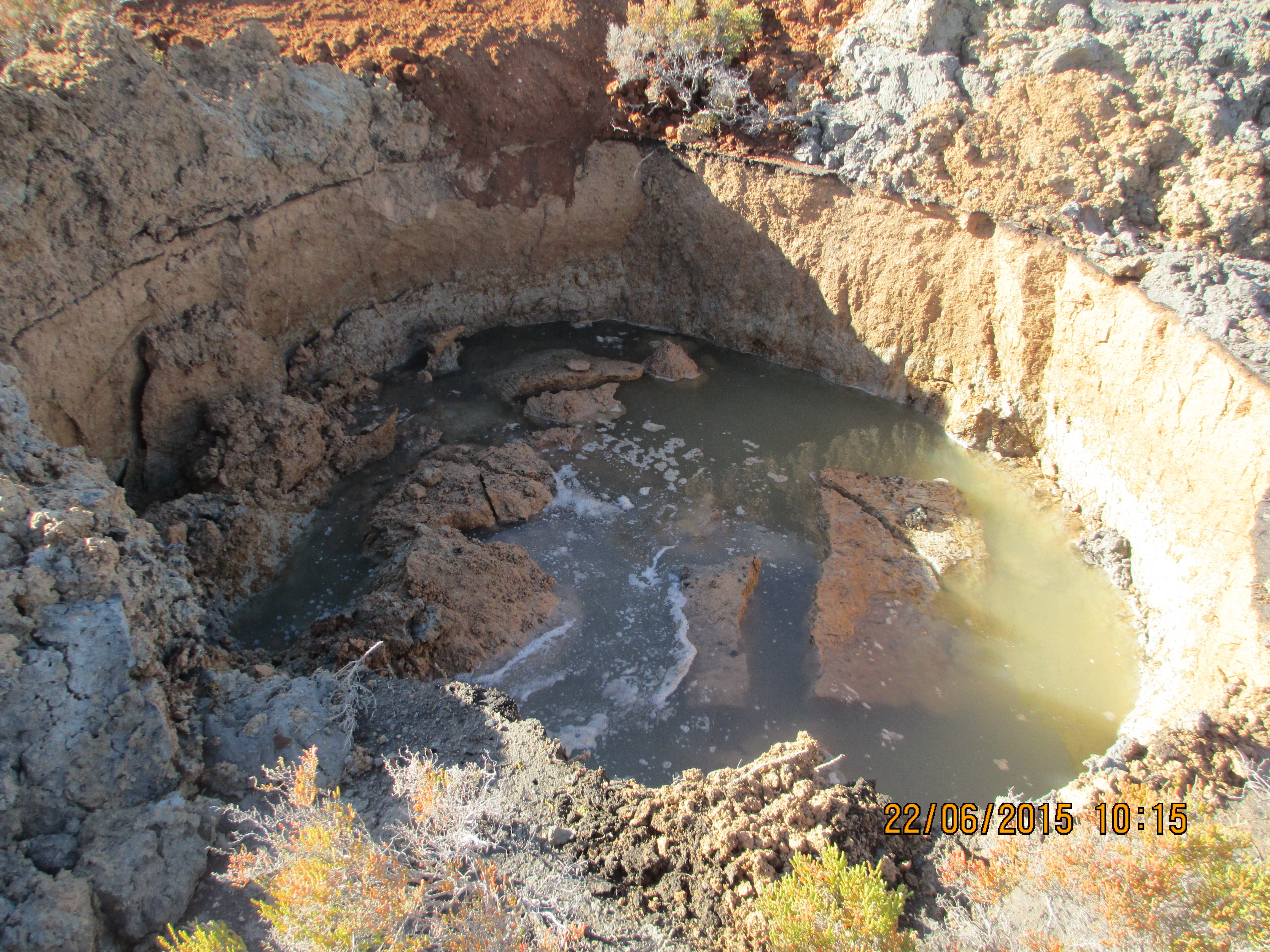
Other random things I have been running with include dealing with some asbestos that was discovered whilst excavating the pipeline writing an Acid Soil Sulphate (ASS) plan and the redesign the pipeline as it crossed through an area that locally has become known as the ‘bog’. The area in question was a concern as the pipe transitioned from an area of pale brown sand to an area of grey clayey sand before going back to sand. From John Morans lessons the mention of clay clearly sent alarm bells ringing in my head. As a result I was then tasked with organising a geotechnical investigation to try and establish an estimate of the long term settlement (which came back as 50mm over the 100m) and then amend the construction method and design to bridge the gap whilst ensuring there was enough flexibility to prevent the joints from opening up at a later date. All very civil orientated but I suppose it prepares me for future roles as a PQE in the Royal Engineers. What was a shock was the fact that this whole episode came as a surprise to everyone, despite the fact that the area can be clearly seen on Google earth. The photo below shows the result of a test pit, which started out as 1m wide by 3m deep trench about an hour before.
Oz PCH – Bomb Shells and Project Roles and Responsibilities Update.
Introduction
Almost at the half-way point through Phase 2 and having covered a lot of ground since AER 1, I thought I’d share the shaping (mostly by me) of my attachment. With regular DAP progress mtgs with my LM, the latest of which (17th July) the Building Services Director sat in on, he decided to drop a small yet not insignificant bomb shell – he has done his best Judas Iscariot impression by handing in his notice to leave JHG (in a month) to work for Westfield Construction (shopping centres). Not good news considering we are in the middle of commissioning, with issues popping up every day, and he is the Commissioning Manager!
The week prior we (the commissioning team) had a re-alignment of project roles and responsibilities. Interestingly my LM still had a hefty work load and was giving himself more! So you can imagine this has raised a number of questions, like; “Who is your replacement and will your position be gapped?”
Roles and Responsibilities
The following are my main roles with basic detail and examples where applicable:
1. System Availability Programme Analysis.
2. Fire System Integration/Cause & Effect Commissioning.
3. Building Performance Testing Management.
4. Performance Testing & Client Witnessing Programme Planning.
5. BIM 360 Field Commissioning Strategy Management.
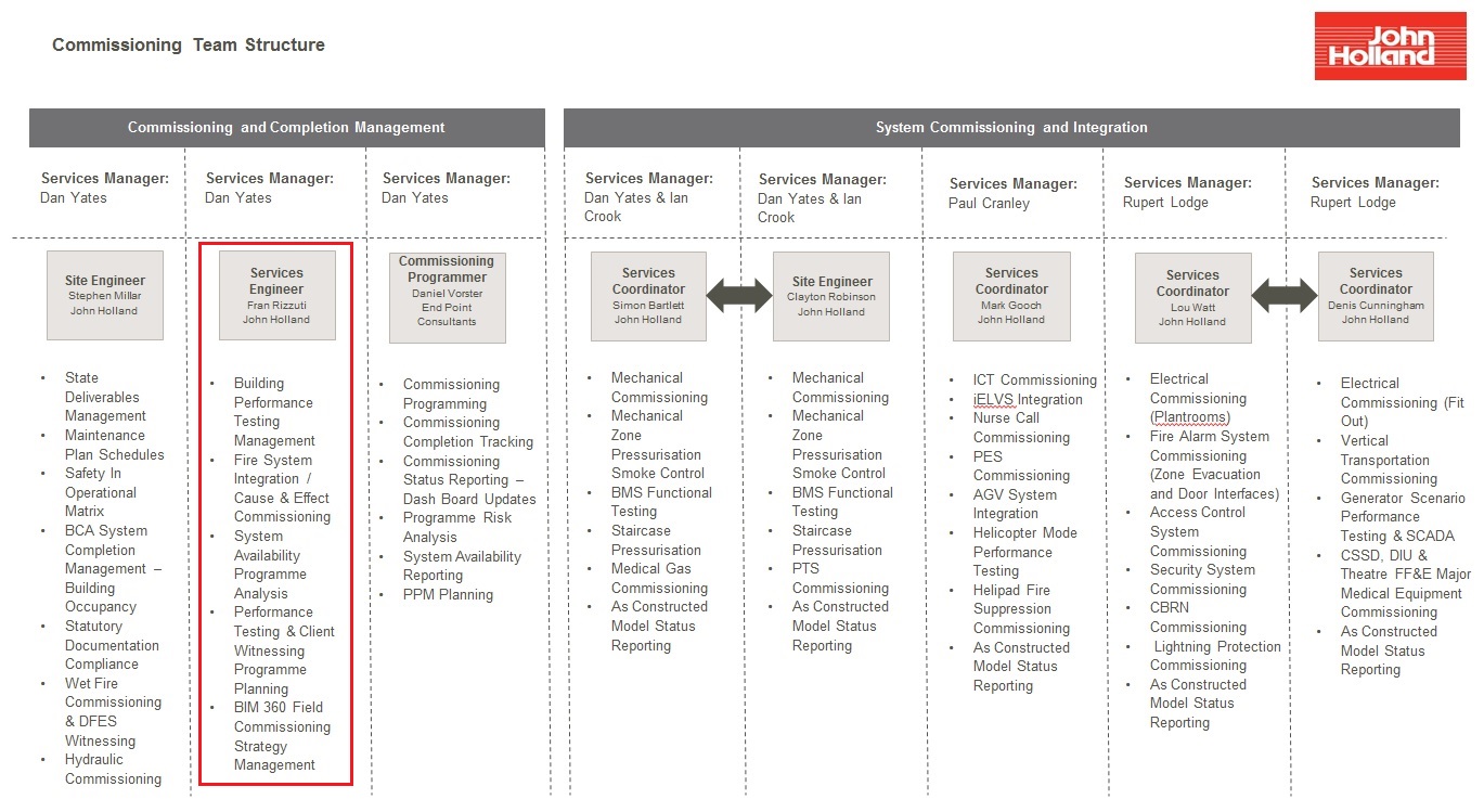
Figure 1. Commissioning Team Structure.
1. System Availability Programme Analysis
This consists of tying in the construction delivery programme with the commissioning programme. There are many factors affecting the ability for a system to remain ‘on-target’ for completion and therefore proves quite challenging to coordinate. A few examples are commissioning delays due to procurement issues; the lighting supplier experiencing manufacturing hold-ups and; late supply of the south side atrium façade affecting balancing of AHUs.
The latter example involved me searching through many detailed shop drawings and the Federated BIM Model to establish which air diffusers and grills are open to the atrium thus affecting the balancing of the AHU they are associated with. If the AHUs were balanced in their current state any building dust and debris would potentially contaminate the ductwork and would require cleaning all over again, not to mention give false air balance readings due to the large amount of air flow from the open space to the atrium. Figure 2 shows the current condition with the photo taken from the ground floor of the atrium with Levels 2 (Central Sterilising Services Department (CSSD)) & 3 (Operating Theatres) both open to the atrium. Both levels continue off to the left of the photo and present a significant opening.
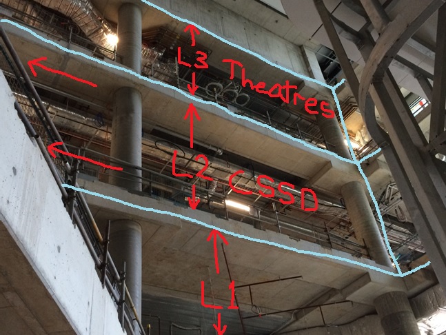
Figure 2. The Affected Open Levels to the Atrium.
The atrium glass façade fitted by subcontractor, Annapurna, is to be 90 mm thick and fire rated to 2 hours. Figure 3 shows the BIM Architectural Model of how it will look once complete (same angle as the photo in Fig1). Figure 4 shows the two levels from on top of the Level 1 balcony.

Figure 3. The Closed off Levels to the Atrium.

Figure 4. Atrium Facades in place viewing from Level 1 Balcony.
2. Fire System Integration/Cause & Effect Commissioning
This is a Cause & Effect Matrix based on a fire/smoke fault condition and explains what various systems should or shouldn’t do in a fire/smoke scenario. Fire and Smoke is just one of ten scenarios where the building is experiencing a fault condition. This particular Cause & Effect is quite complex especially when you consider that in normal operation mode certain rooms/areas are either negatively pressurised (infectious disease ward) or positively pressurised (operating theatres). Essentially the fire/smoke management system is stand-alone and hard-wired into various Variable Speed Drives (VSDs). These control specific AHU fans, fire and smoke dampers, wet and dry fire suppression systems and fire/escape door opening/closing systems. These are all monitored by the Building Management System (BMS).
3. Building Performance Testing Management
This is testing and assessing the performance of various systems and ensuring that they conform to Australian Standards, the design specification and ultimately meets the client’s technical specification.
4. Performance Testing & Client Witnessing Programme Planning
This is taking the above various performance tests and allowing the client to witness them. An example of which is the UPS room which will be covered in a separate blog.
5. BIM 360 Field Strategy Management
This consists of managing and coordinating the documentation and data entry of all commissionable systems into BIM 360 Field in order to meet the client’s requirement of Level of Detail (LOD) 500. This has meant creating a Commissioning Register in BIM 360 Field and a process that enables the commissioning team to track the progress of each system through its commissioning. Being a bespoke and innovative method of information management and integrating it with BIM Models has meant learning an entirely new way of doing business, one which has required deeper understanding of REVIT (CAD) Models and BIM in general so that I could conduct training workshops and aid the subcontractors in their understanding.
An additional task, which was confirmed in my latest CPD/DAP mtg by the Building Services Director, is for me to write up the BIM 360 Field Commissioning Implementation Plan for the PCH Project. Producing this document now may seem a little back to front considering we should have met Practical Completion in early July 15. However, BIM 360 Field was not procured until 2 yrs into the project and the original BIM Project Implementation Plan (by PDC) therefore had no mention of 360 Field. In addition, we are only now learning the challenges in its utility as a commissioning progress and information management tool. It will hopefully be similar to a lessons learnt document you might read from a previous operational tour; its intention to provide important information and help write a generic BIM 360 Field Commissioning implementation Plan. This will then aid JHG Corporate Staff in potentially combining it into a greater JHG Strategic BIM Implementation Plan. This gives me a great opportunity to re-inforce the recommendations that fell out of the conclusions I made in my TMR on BIM – What are the advantages of Building Information Modelling and how does its implementation allow John Holland Group to become the market leader?
In Other News
Han and I went to see Clarkson, May and Hammond Live at the Perth Arena. Excellent, with supercar porn (figure 5) and top banter aimed at the BBC for Clarkson’s Top Gear faux pas. The motorised lacrosse (figure 6), clearly car football but renamed for legal reasons to avoid Top Gear backlash, was hilarious even though the final score was Eng 4 – Aus 5.

Figure 5. Supercar Porn.

Figure 6. Motorised Lacrosse.
Finally, and proving that even when you’re out on a social you’re always learning, I experienced an excellent example of an innovative carpark system. It is the underground carpark of the Perth Arena and as you can see from the photo in Figure 7 at the end of each row there are LED boards informing you of how many spaces are free in that row. Then when you turn in to that row you see a line of LEDs, red or green, with one next to each parking bay – the green ones being empty. Like Aleksandr the meerkat would say “makes finding a parking space simples”.
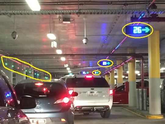
Figure 7. Perth Arena Advanced Underground Carpark System.
