Archive
Site Two Fifty One – Prop Installation
Site Two Fifty One – Prop Installation
Despite site activities being focused on the remaining piling works (17 CFA piles to go), as always there is a push to do multiple other activities all at the same time, but luckily not quite in the same place.
Groundforce Shorco prop installation. The aim is simple – put in 9 props and remove about 1500m3 of water and about 10,000m3 of sand and gravels (and some clay).
Prior to now sections of capping beam have been poured, shear stubs were embedded and prop end plates were fastened.
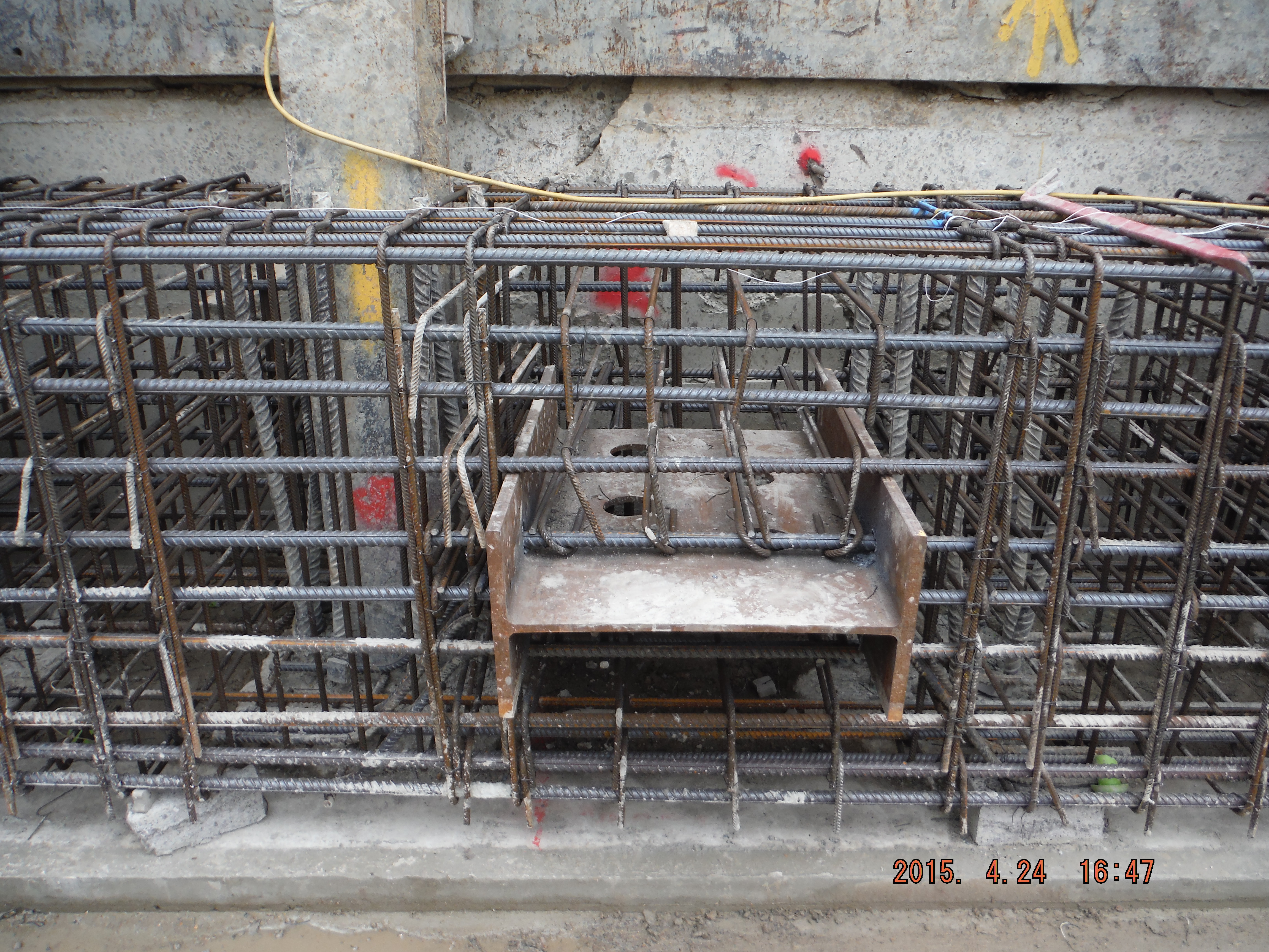
Shear stubs installed
End plates being fastened to the capping beam
The general principle is to excavate to underside of capping beam, install a prop, excavate in order to dewater, excavate more, dewater more, install the next prop and repeat, 9 times (9 props), all while avoiding piles and segregating the exceptionally beach like sand and gravels (removal of this is less than half the cost of clay muck).
The first 2 props were installed this week and aside from problems with crane time there are a few other interesting points to consider.
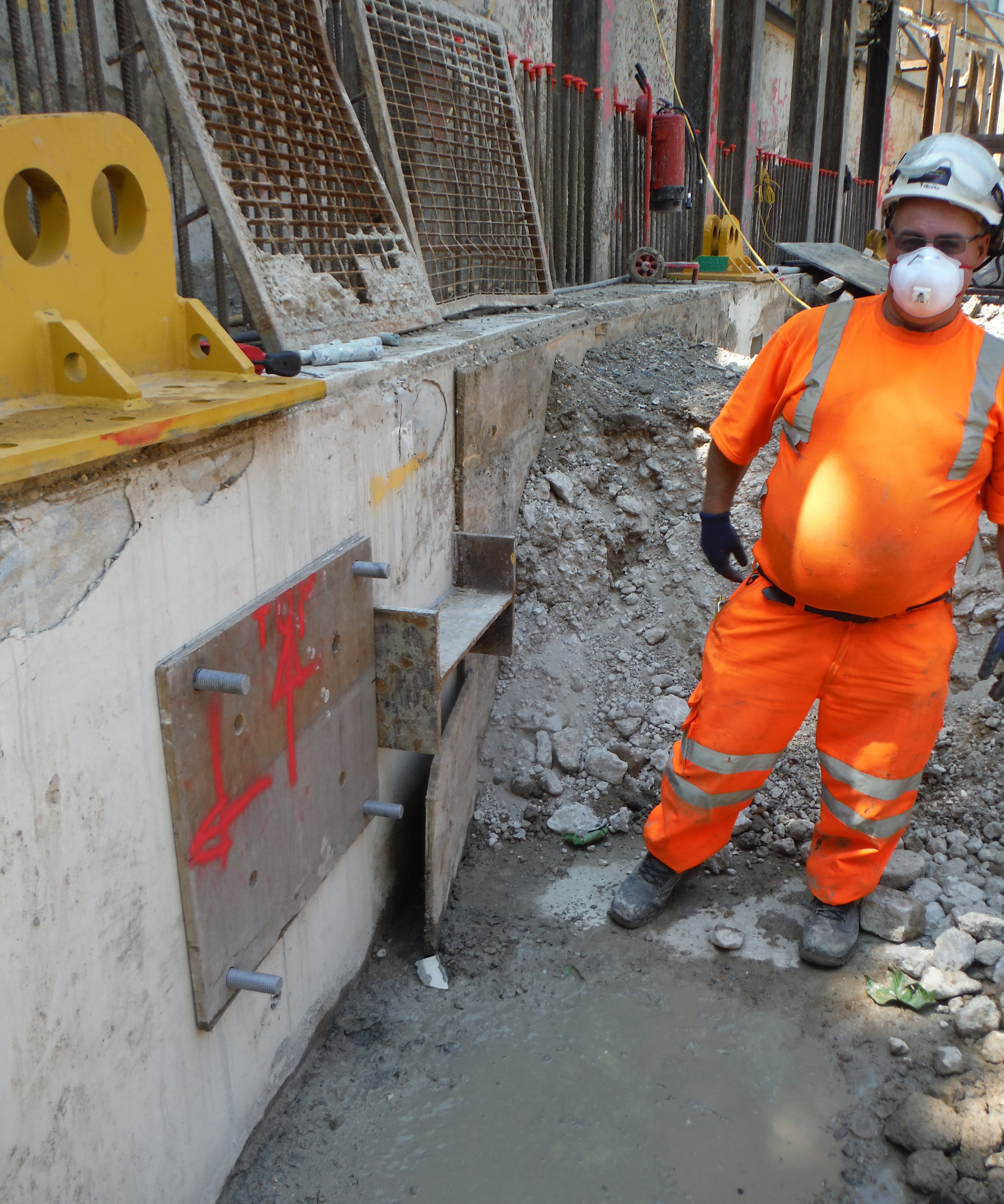
Problem 1. End plates not meeting with shear stubs. Despite very careful installation of the 4 x M30 bolts embedded 250mm into the beam using resin, the end plates did not quite have full contact with the shear stubs. Options: weld a connection, use a grout pack, place shims or do nothing (assuming with the applied prop pre-stress the gap would close) to provide a load path. A good weld is difficult to achieve in a 30mm deep recess and the plates may well be damaged when the weld is ground off at the end of the works. Using a grout pack is possible but with movement of the prop (thermal expansion in the day) this might crack. Shims – the best and simplest option – this was chosen and on referral to the designer, the recommendation was to use S275 steel.
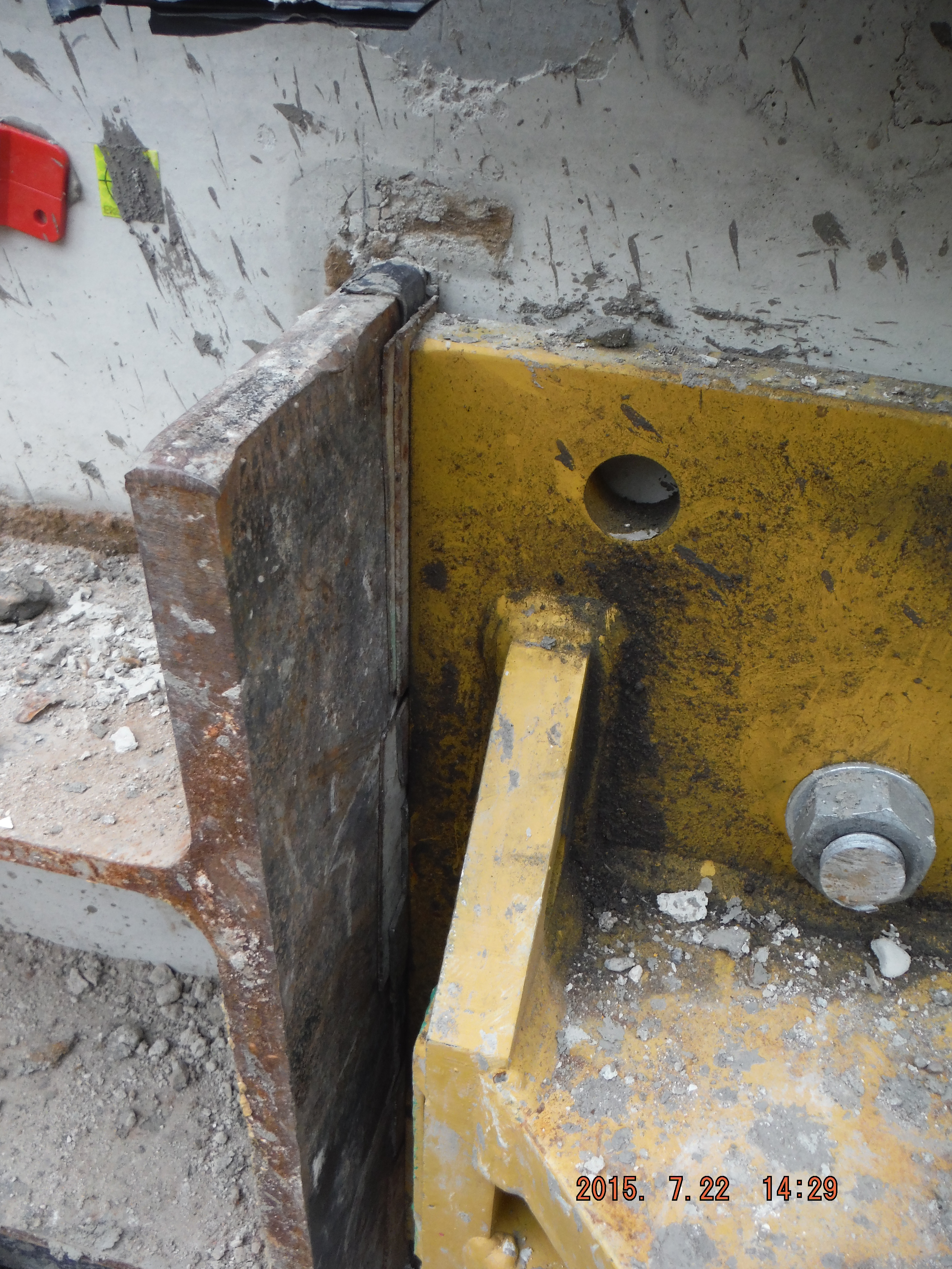
Shims used to provide path for load transfer
Problem 2. Not all of the capping beam is complete. The capping beam (which will form an entire ring around site) is used to transfer vertical load (from the buildings above) to the piles below. It is also being used to prop against horizontally.
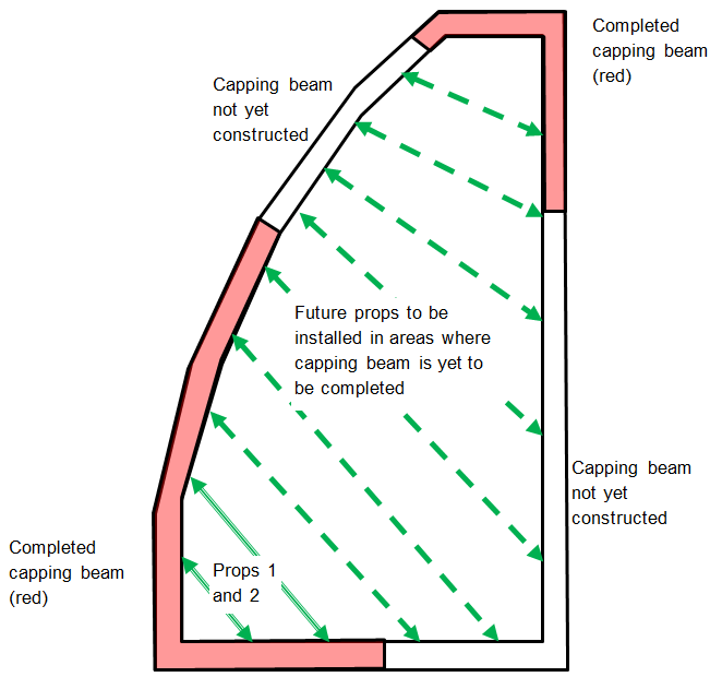
Diagram shows line of completed capping beam (in red) with future props to be installed (dashed green arrows) in areas of capping beam yet to be cast.
The question is, is lateral load transferred along it (as if it were a steel beam) to the ground at the corners or to the secant piles below acting in a sort of individual cantilever/domino fashion. The secant piles have 900mm of reinforcement cage embedded into the beam and are at 1.2 centres with male C30/40 piles and alternate C10/15 female piles. On further consideration, the female piles are only there to provide water resistance, so the load is transferred into the top of each pile down into the ground (embedment anything up to 23m for the permanent condition).
This can be modelled as follows:
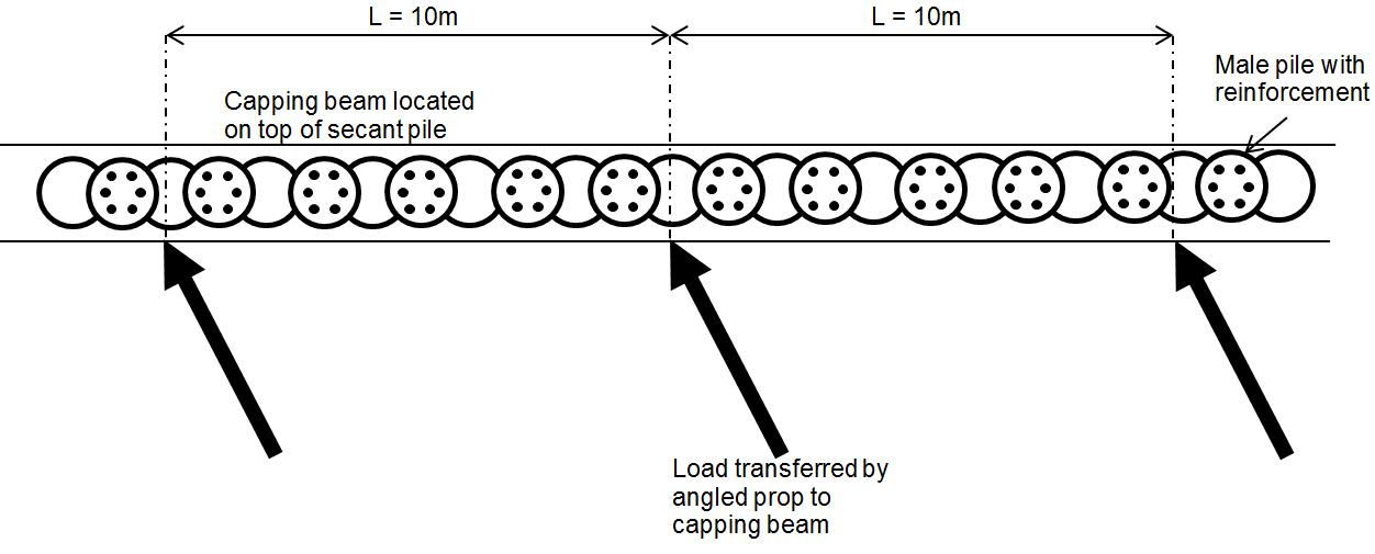
Plan view of capping beam showing prop loads applied to beam
By splitting the capping beam into sections around the props (10m spacing between props in this case) each pile within the section can be considered to carry part of the prop load. It is proposed the nearest two piles will see more load than the next two and so on. If each prop and pile section behave in this way it implies that as long as the capping beam is completed to at least midway between the next prop the system should work. That’s the theory anyway!

Plan view showing prop load transferred horizontally and vertically into the capping beam and onto the male pile reinforcement

Props 1 and 2 in place
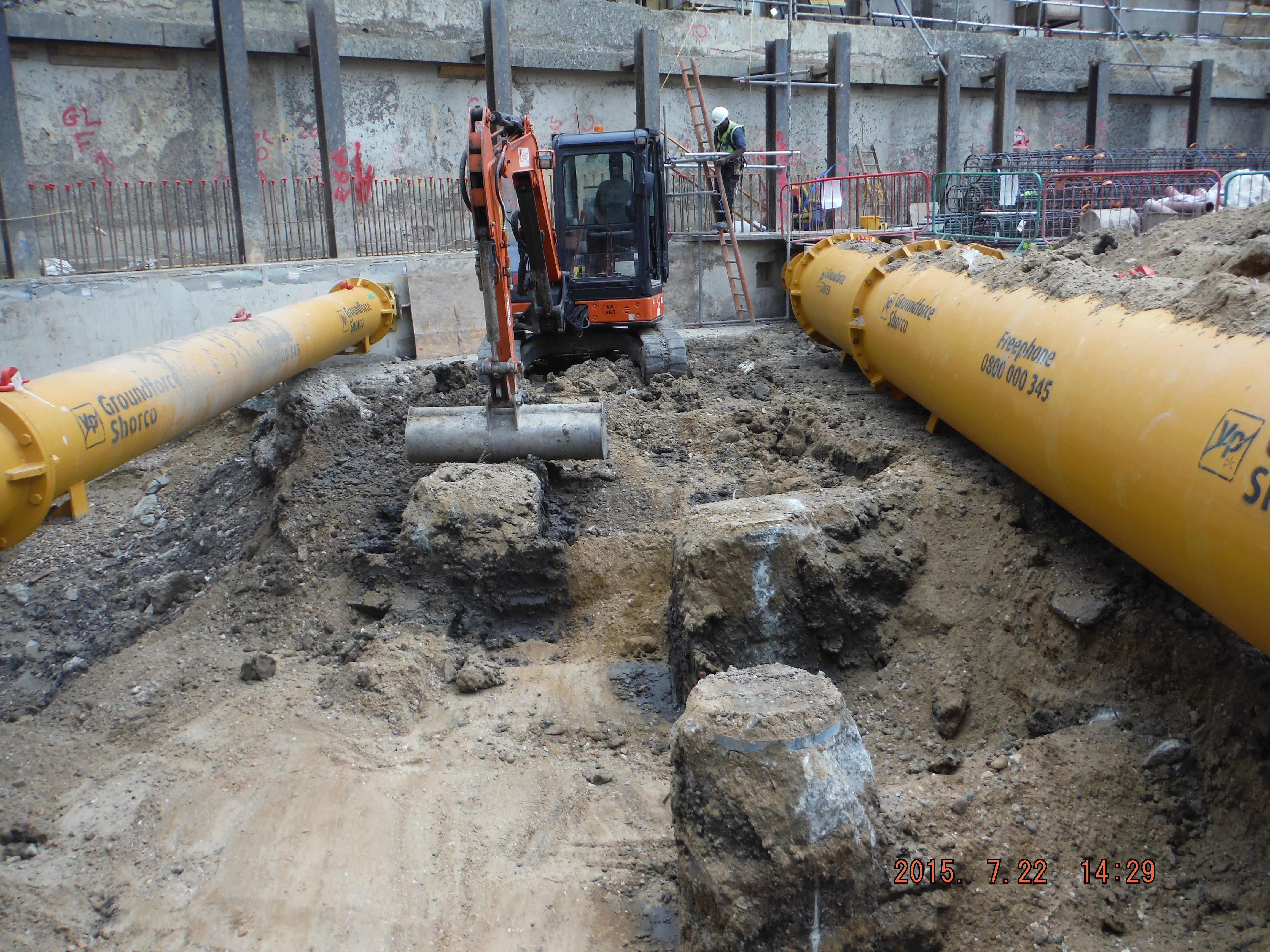
Excavation between bearing piles
Problem 3. Remaining props are likely to be installed prior to the capping beam reaching 50N/mm2. Similar situation to above, capping beam is designed for permanent loading, temporary design is for 30N/mm2. Looking at the cube results, this strength is reached between 15-25 days. Therefore, in theory, this is when the props can be loaded. To be more sure additional cubes will be cast and crushed to understand the rate of strength gain between 7 and 28 days a little better. Additionally the plan is to use thermocouples within the beam to understand the actual temperature of the concrete. This could then be replicated in the curing tank and rather than adhering to the 20 degrees standard, which should produce more realistic cube strengths similar to actual conditions.
Contract Update: Work on site is currently progressing at risk (no formal contract) – the monthly instructions to continue work ran until 20 Jul 15 and the next one (as far as 20 Aug 15) has not yet been signed off. The client has hand shaken on the main contract with Ray O’Rourke at £119M so clearly all will be fine!
Handy – from Phase 1
I thought I would post a quick note to mention something from Ph1 that I have continually found to be useful, from a civils point of view obviously. Quite a lot of my time on site is centered on rebar drawings, which can seem fairly impenetrable. Although it was only around a days worth of taught time in Ph1, and incorporated into a design exercise, the lesson on reinforcement detailing has continually proved invaluable in allowing me to add some value and hence afforded me some credibility on site. Don’t get me wrong, I haven’t had to DO any detailing (yet), but understanding how I could means that I can read the drawings and conduct checks.
Multiple Drawings
Following on from that I picked up an error in some rc walls the other day which are going to house some utilities. The rc chambers are being built to hold pumps and ‘stuff’ which will tie into main water tanks (chilled and non potable). The water tanks are steel and are off the shelf, arriving at the CUP at a later date. What’s interesting, in inverted commas, about the error is why I picked it up. I was using shop drawings, for which no contract drawings exist as the tanks were not part of the original design work. (There is simply a bit in the specs saying that there are tanks required and that the Principal Contractor (PC) is responsible for sourcing them.) The PC was using an updated set of field drawings. These are typically slightly different to the contract drawings in as much as they account for the amount of steel that is going into whatever feature of work it is they are for. A cut from the drawings I was using are below, with the offending bar highlighted in red.
Excerpt from PC Shop Drawings
That bar, is a 5/8” diameter. (annotated ‘#5’) bar which should go on each corner, as you can see in wall W-02, with the remaining bars being number 4’s (#4) which are ½” diameter. On site #4s had been used all the way across. I was able to ascertain that the #5s hadn’t been called out on the field drawings, which is an error on the part of whoever produced those drawings. So the error arose, and was caught by the fact that multiple versions of the same drawings existed. If we had both had the most up to date drawings the error may have slipped by. I guess the lessons here are try to always obtain the most up to date drawings, and ensure that they are correct! This brings me onto another point…
RFI Tracking
… How does everyone else keep track of the RFI’s and various changes that occur to the contract drawings? When I go out and conduct checks I always take the contract drawings and the field set. Before I go out though I have to print out the relevant contract drawing and highlight the RFIs and amendments to it in pen, using a hardcopy set of drawings onto which all RFIs and amendments are noted as they come in. A picture of what on earth I am talking about is below.
Mandraulic Updates on Conformed Contract Drawings
This is a drawing from one of my last checks. In pen are the RFI numbers and where they relate to. (ignore the bits in black, they are notes from the inspection itself) Before I go out I have to read what the RFI was and what the amendment is. Fairly laborious. Now, the pc who is clearly doing fairly well for itself has deigned it more productive to supply all its engineers with iPhones and iPads, with indestructible cases. They are all therefore able to download any drawing whilst on site. All their field drawings are updated by CAD Wallahs and replace old copies as RFI changes occur. Since the government doesn’t have CAD Wallahs its contract drawings don’t get the same treatment so we are stuck on the original conformed set, with ever increasing notes and cross references to RFI numbers.
Since everyone else is working for high flying engineering contractors I am curious, how do you do it?
LEED
As I suspected in my last blog the LEED issue has reared its head again. I sent back a submittal ‘E’ coded (re-show) for not having the required third party certification showing VOC levels. The pc called, stating that the manufacturer doesn’t have third party certification, nor is it willing to get it for one product on one job because it costs c. $30k. I suspect that the pc is less than enthused about paying either. From a government point of view and on reading through the specifications there is a very clear requirement for certification. As far as I am concerned it is the contractor’s responsibility to obtain the certificates, a point I will articulate. However, in the interest of not being a complete douche about the situation, and in the interest of maintaining positive relations I am currently investigating an ‘out’ for them. I know that any material that is installed out of LEED compliance can be ‘offset’ through focusing on the installation of super low VOC content material in the vicinity of the non-conforming material. What I am less clear on is whether this is for accidentally installed material, or as would be the case here deliberately placed material. I have sent the question to a LEED appointed person who sits with the client for their consideration. Another option I will table is the use of a different material altogether. The problem with this is that I have absolutely no input / exposure to the procurement process where I am at present. I don’t really know if this is a stupid recommendation but I will speak with someone at the pc end and ask, since we are currently on talking terms!
And finally
This is a picture from the historic Ft McHenry. It is where inspiration for the Star Spangled Banner comes from and is the site of an unsuccessful British attack. The bridge in the distance, which you can just about make out, is where the British Ships bombarded the fort from, retreating, presumably, when they got bored. The distance to the bridge was slightly further than the reach of the canons in the foreground, but just about the maximum range of the British canons.
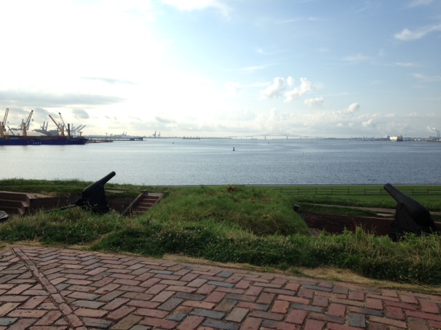
Fort McHenry
I tabled the idea of a future OPD event to the newly arrived District Commander that we should do a battlefield study about how the Brits could do it better next time.
