Archive
Site Two Fifty One – Environmental Problems
Site Two Fifty One – Environmental Problems
During the removal of spoil from Two Fifty One to enable the installation the Groundforce props some of the lorries of muck were rejected from the tip because they smelt of diesel. I had no record of a diesel spillage on site so it all seemed strange. The loads had to be returned to site because the tip was refusing to take them and the carrier (Erith) were not able to dispose of them. Typically as the excavation progresses it becomes harder to separate/segregate anything. Therefore having excavated material returned to site is somewhat of a problem.
Contaminated material being stored left of the ramp access into site.
On further inspection of the area the muck was being excavated from it was identified that some of the sand and gravels had turned grey. I.e. it contains diesel.

The photos show the grey streak in the sand and gravel showing the diesel contaminated ground.

Aside from the fact that the majority of the area had been excavated and loaded onto tippers (albeit to then be returned to site) it was clear where some of the more affected areas were which should help reduce the spread of contamination.
So what?
The extent of the problem is just getting started (no environmental agency involvement yet) and as it has happened and now stopped, typical actions – such as using a spill kit/isolating the source are redundant. Therefore I have highlighted some of the post incident considerations we are currently going through.
- Stop sending muck away from the site (significant impact on programme as the key task is to remove muck at this stage).
- Identify what the contamination is. Initially, this will be done by using a Photo Ionization Device – this gives a rough and ready level of volatile organic compounds in the sample. Below 50 parts per million is apparently acceptable. You don’t need much diesel to make things smell of diesel so I am hoping that is the case…
- Record/report the incident, brief the site team on the importance of reporting spillages.
- Once we know the extent and type of the contamination the loads can be removed. Worst case the muck will be removed as hazardous waste at £1700 per load which comes with permits to move hazardous material. We are paying about £200 at present so that would have significant commercial implications!
- Attempt to keep to schedule with a mini-mount Everest forming in the corner of the site!
More widely here is a brief update on drainage and reinforcement installation.
Drainage.
We have just started to install below ground drainage in the Basement Level 2 raft slab. We are using the Saint Gobain timesaver inspection chambers and Ensign pipes. For future reference, Ensign is a significantly lighter product, more easily moved/handled and costs much less (we have made a circa £30K saving by requesting to use the lighter system).
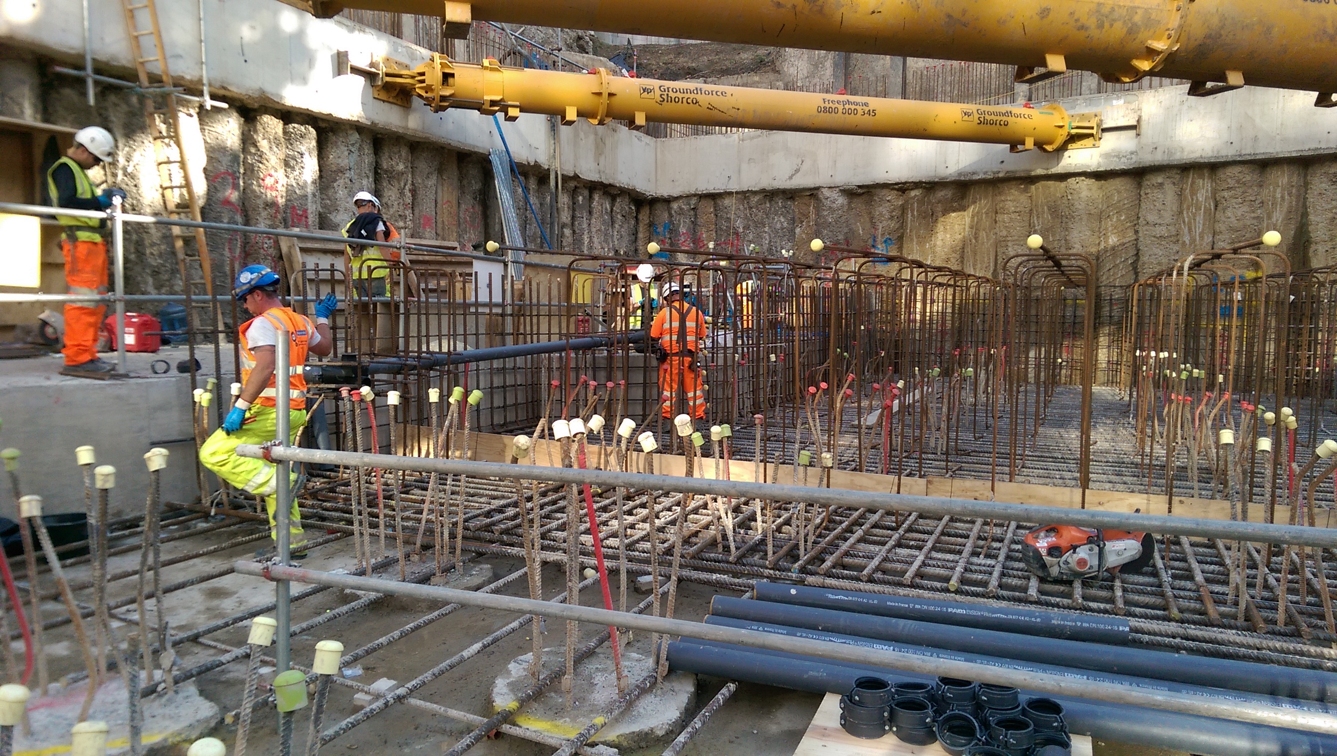
The drainage is being installed within the area between the bottom and top mats of reinforcement.
What I wish I’d known:
- Testing methods – something about bungs, and air bags. More to follow when I understand what that is.
- That a foul gully run cannot rapidly change gradient in a run because the solids will separate out.
Basement Raft.
The 2.1m deep raft foundation is currently being constructed. It is quite an impressive site seeing 40mm, 12m long bars being positioned by hand.
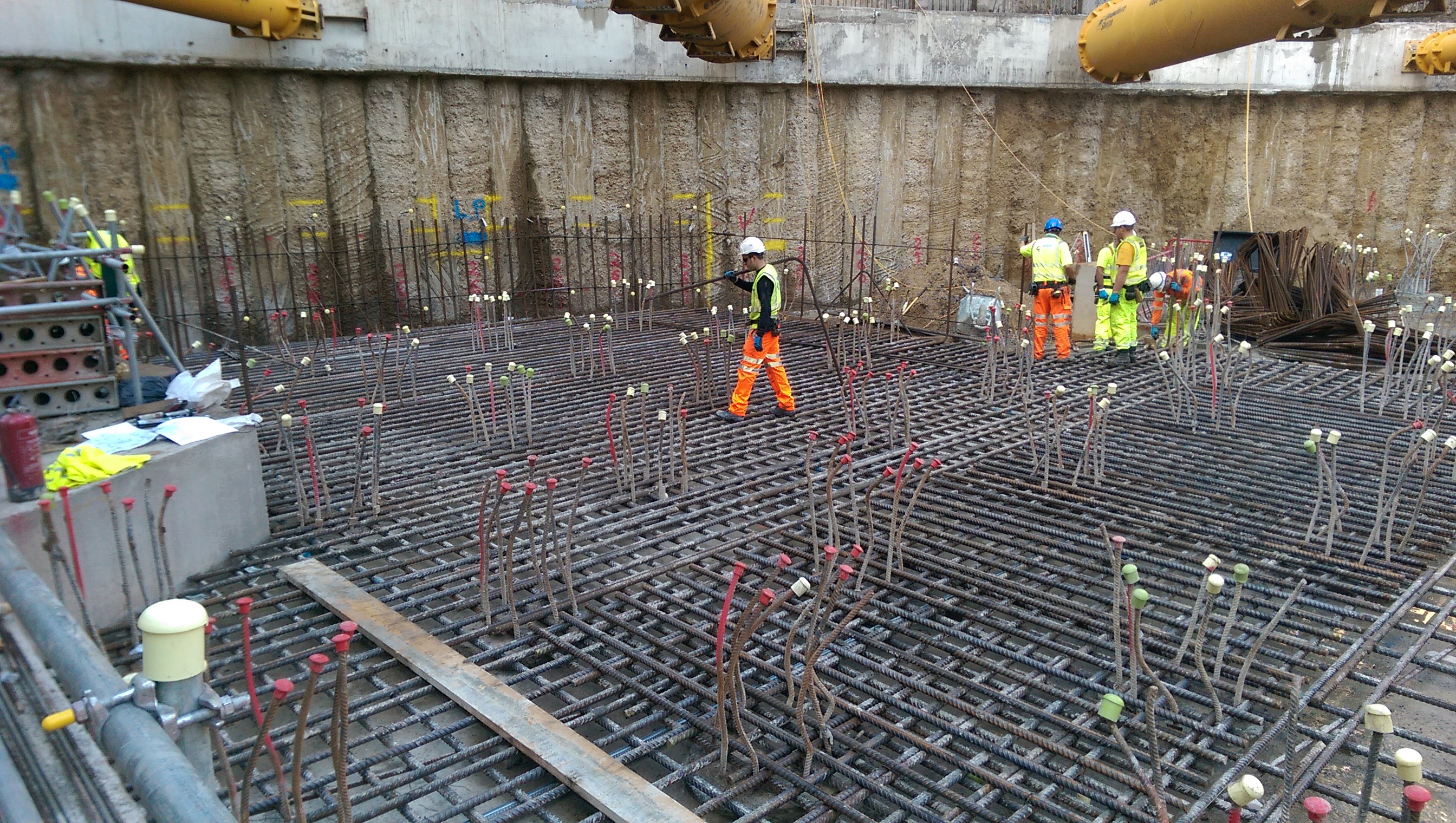
Raft bottom mat reinforcement being installed.
The original aim was to use Pecafil formwork (permanent sheeting) for the concrete pour. Due to the number of piles this is proving a little more complex. As the ground is excavated, pile reinforcement acts a bit like dragons teeth preventing easy access to return to backfill around the raft. The plan is continuing with the idea to use a small dumper to move material back into position, rather than switching to the use of shuttering. Again, more to follow on the success of this plan!
A final thought:
There is a slab (450mm) which will be poured across the site, including on top of the raft making a total of a 2.1m deep foundation.
There is a bottom mat to fix in the raft and a top mat to fix in the slab.
Would you, a) fix the bottom mat, pour the concrete raft then fix the top mat and pour the slab? Or, b) fix bottom and top mat, then pour raft, then pour slab (i.e. do pours with all steel fixed)?
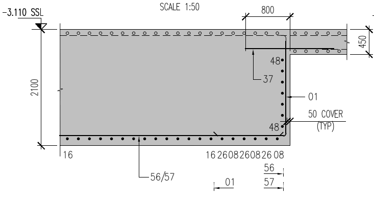
Raft foundation comprised of 450mm slab and 1650mm raft.
The Seven P’s.
In should come as no shock to anybody that water in is pretty expensive in South Australia, costing in the region of $3.32 per kl. The project received its first bill this month (don’t ask me why it has taken this long to get here) that covered the start of the project Dec – Apr which was quickly followed by a second covering May – Jul, with the total over $350,000. The cost arose from the fact that water was required almost 24hrs during the summer months for dust suppression during the bulk earth works. Surprisingly this cost was not captured in the budget for the project and was excluded from contract with the subcontractor responsible for the earth works, so it will eat in to the profit for the job.
From this episode the project team were tasked with carrying out a review of the budget to identify any other holes and quite a few were identified. The main one sticks with the water theme as it became apparent that the cost of filling the various systems on the site (in the region of 30Ml) with demineralised water had not been accounted for. The options for supplying this were limited, using the reverse osmosis plant at the local power station or getting in portable reverse osmosis plant to site to produce our own. The power station was discounted because in order to fill the tanks on site we would need to fill the 5km worth of pipe to get it here and find a method of pumping it. The current plan is to use a subcontractor to bring in temporary plant to produce it on site. This is producing a number of issues in itself, the main one is trying to find a subcontractor with the capability to do this, we are currently looking at GE supplying the equipment and another subcontractor to install and operate. Further issues we will need to work out on site include finding space for the plant, power and water to operate the plant and a method of discharging the brine, all of which the project will have in the future but not necessarily in time.
No one is sure what this is going to cost but best estimates coming from our procurement team at the moment are around $500,000, plus the cost of the feedwater approximately $100,000. This is likely to fall to John Holland, as the head contractor we are ultimately responsible for commissioning the plant (although no doubt we will try and push some of the cost back to the client).
Looking for causes as to how this could have been missed I think it’s quite simple, in the rush to get shovels into the ground after signing the contract a draft program was produced, with no product or work breakdown conducted to back it up. As the project progressed no one has had the time revisit the program so it has just been updated where necessary, which is fine for sequencing works, but doesn’t identify items that are missing altogether. In their defence I know at the time the project team was pretty limited and they were under immense pressure to get the project started.
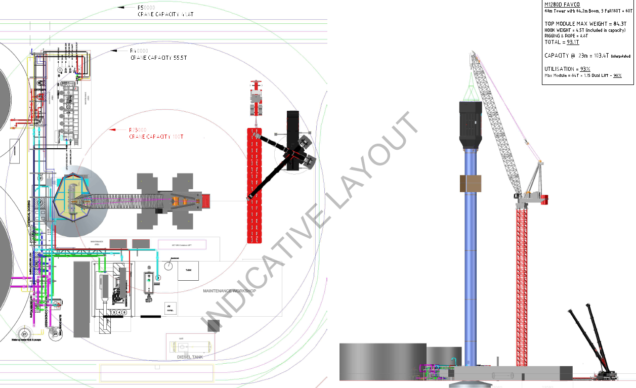
The picture below is just to attract some attention to this blog, it shows the planned lifting strategy for the 115m high tower, hopefully before I leave site in November.
Defence Reporter
I am not sure of how others come by their Thesis ideas, however I certainly didn’t find one drop in my lap from working on site and so had to go looking. I would encourage those in Phase 1 to start thinking about it before leaving Chatham. A resource I have found for contemporary research from DSTL is Defence Reporter:
https://www.gov.uk/government/publications/defence-reporter-mod-research-reports-on-athena
The periodical only gives the abstract and you have to apply for the reports which appear to get posted. Mark said he has used it before but the system appears to have been formalised more since. Some of the reports may be worth applying for, most certainly aren’t. The above link gives the back copies and you can subscribe, the issues are irregular but at worst it is four extra emails a year to delete from your junk mail!
Gut Feeling
Pre-amble
First I must apologise for not blogging for so long, as I’m sure you’re all on the edge of your seats waiting for my next instalment; I should have listened to those who warned me about parenthood!
This blog is regarding the design of a previously discussed project and conveniently reinforces what both Damo and Guz have just blogged about.
The Project – ETAP Lifeboat Maintenance Padeyes
Each of the 3 lifeboats on ETAP are lowered using a pair of winch cables attached forward and aft. The cable release mechanisms are sufficiently delicate that carrying out maintenance on the lifeboats requires maintenance strops to be used in order to provide a secure fixing to the structure in case of a release mechanism failure (size 10 boot). Due to new lifeboats being installed a couple of years ago, the maintenance padeyes are now considered under sized and out of alignment to the boat fixing locations. See figs 1 & 2.
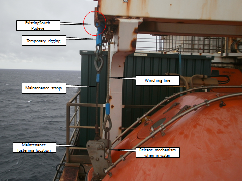
Fig 1 – Existing South padeye

Fig 2 – Existing North padeye
The original solution
The solution was simple. Cut off the existing padeyes and weld new, uprated padeyes in new locations. See fig 3 & 4.

Fig 3 – Proposed South padeye

Fig 4 – Proposed North padeye
So what’s the problem?
This project has been ‘hanging around’ for some time and hasn’t really moved forward, not helped by the ever changing personalities (see future blog). Following a couple of meetings back in June, the BP Offshore Execution Lead expressed concern that ‘it just doesn’t feel right’ and although I agreed with him, I just put it down to being new, as well as accepting that circa £100k had already been spent getting this project through the design phase so far, surely it must be right?
The following were highlighted as being a concern;
- It was understood from handover that the lifeboats would remain in service. The plan requires a significant amount of scaffolding around each lifeboat which by virtue of the restrictions, takes the lifeboat out of service.
- The plan had all 3 lifeboats being worked on at the same time. This just wouldn’t happen due to the obvious sensitive nature of the lifeboats.
- The plan required an amount of hot works (grinding/cutting & welding). Although the lifeboats were not in an area which required additional measures to be taken (use of a habitat, for example), there was still a risk to the lifeboats themselves and layers of protection would be required; reinforcing point 1 above.
- The padeyes would require testing once welded in position. The plan used a jig that wrapped around the davit structure see fig 5, so that the forces would be self-contained and not add to the davit arms themselves. This required both heavy and awkward lifting above a lifeboat and inches from the edge of the platform.

Fig 5 – Test rig
The solution
Following a ‘deep dive’ an alternative idea was suggested which was solely a bolted design, see figs 6 & 7.

Fig 6 – New North padeye design
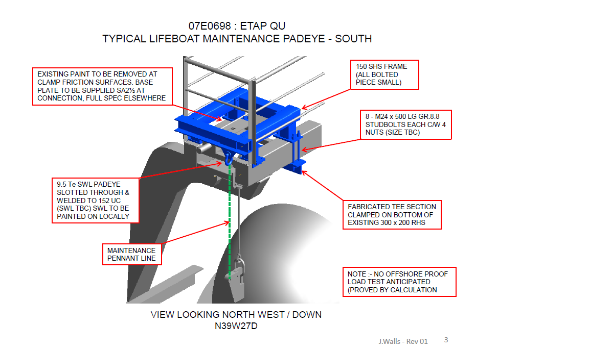
Fig 7 – New South padeye design
This design had the following benefits
1. No hot works are required which means less protection and less scaffolding reqd, which leads to a quicker install and a shorter time to get the lifeboat back into service.
2. Potential to construct using rope access only from the platform above. This would mean no scaffolding reqd and potentially reduce costs.
3. The entire frame could be proof tested onshore using a mock up davit arm/frame, and then re-assembled offshore.
So why wasn’t this option considered in the first place during the Appraise/Select phases?
It was, but as I understand it, was not selected because it did not look aesthetically pleasing!
Now what?
I am expecting a Project Change Notification (PCN) of between £50-100k to get this re-designed and ready for offshore construction, and potentially a delay to the ‘ready for construction’ date.
Conclusion
Even though a significant amount of time and resources had been spent on designing the solution, it does not mean it’s necessarily the right one. If it doesn’t feel right, it’s worth doing a ‘down, test and adjust’ to make sure the direction of travel is the right one, especially if the project has sat idle for some time and/or the entire team had changed.
This project is, technically, as simple as it gets. But from this blog and my previous, you will see that it is not straight forward and often it is the ‘so whats’ surrounding the project which add most of the complexities and frustrations.
In other news
Currently planning for phase 2 of the Grand Design, which incorporates replacing the boiler (expect a separate blog on this), getting drawings done for proposed extension and getting the final 2 rooms ready for move in. Pics to follow.

How big is the bus?
I am not sure whether the client usually gets to see the value of each of the subcontracts but it appears that we do. So for my FtIG project I can see that ‘the bus’ is costing us approximately $110,000 or 27.5% of the contract value. From what I have seen so far this pays for two slippery salesmen and an OAP in a portacabin who is going to run the site. Although we are supposed to get the information it has been accidentally added into the emergency contact submittal, which was clearly part of a larger spreadsheet, but you can get the idea
Contract values
Flippant as I may be this clearly also considers the various overheads that have been incurred not least the cost of tendering for the project and the 4 months of paperwork that has been done prior to getting out onto site. This in cash-flow terms is a significant burden for a small company. Also in there will be the risk for things not going well, something that is quite likely in replacing an old system. I am not sure whether Greg or Steve have any thoughts on the general mark up on something like this.
As far as progress goes, yesterday I met the aforementioned OAP who is to be the superintendent, Quality Control Manager and Site Safety and Health Officer (SSHO) and some materials were delivered. I took the opportunity to get some shots of the interior:
Left: Air conditioning unit not being replaced. Right: Two boilers being replaced.
Left: Three pumps, to be replaced with two pumps.
Right: Domestic Hot Water Heaters to be replaced.
Total Deadlock!!!
Just before my summer leave I attended the most frustrating meeting I think I will ever endure…it made a TFH ISTAR planning co-ord appear proactive!
The background
The embankment that approaches each bridge abutment has a series of piles called CMCs (Continuous Modulus Columns). These piles are placed on a 1m grid over the width of the road for around 50m. They do a number of things but mainly they stiffen the embankment material as they are displacment concrete piles and secondly they transfer some of the load through the constructed embankment to the stiff clay below. They contain no ReBar and are designed to fail if heavily overloaded.
The Problem
Given that the CMCs are not reinforced, they are designed to work in a specific way. Any structural movement will eat in to the tolerance of the CMCs, this means that it would be crazy to install the CMCs whilst our site is still undergoing large amount of settlement we’re still experiencing. Whilst the settlement is starting to slow it has not reduced to the level the Vibro Minard, the subby that is installing them has specified.
The Sticking Point
- Vibro will not give a warranty on the potential for differential settlement of the installation until the ground is at the strength originally specified.
- WSP, the designer, will not check the original spec or conduct any alteration without a FULL check of the whole scheme (big £££). Clearly they can see we’re over a barrel and know something has to give. Their argument is that a reduction in platform strength may have a fundamental impact elsewhere and that requires checking.
- We only have a six week window to get this done before it takes over as the critical path and causes programme delays.
- Kent Council are unlikely to accept the embankment without warranty (we don’t want to ask the question as it will likely open up a huge amount of questions and interest).
- We don’t have the budget to cover the warranty as the project is heavily in debt and this sort of warranty would be for an unknown sum given that no one internally really understands the actual design enough to predict what may happen.
We left the meeting looking at each other saying ‘so what now’.
So What
Quite simply we’re having to wait for the ground to ‘Get A Grip’ and toughen up.
We’ve conducted a number of onsite tests to check the current strength in the ground. The good news is that it’s higher than we expected based on the original model and pizo data however it’s not quite as high as we need.
We have asked the designer look over the findings a predict what the ground strength will be by the time Vibro mobilise if we give them the thumbs up now. It’s looking good, so fingers crossed.
The Disappointment
The sad thing was, everyone sat around that table knew how to solve the problem but hid behind lines like ‘this is what my design manager has said…’! Whilst I understand the requirement to make money, I will never understand the mentality that it is ok to do so whilst others fail, sink and lose out. What made it worse was the lack of spine demonstrated, if you’re going to represent your company then embrace the policies they set, don’t hide behind people who are not present in an attempt to deflect the criticism away from yourself.
The Good News
We have a structure that is starting to look like a bridge, peirs and all!
Small tweeks…
I’d like to echo Damian’s point when he said that it’s important to question the design. It’s not just that the design might be wrong, although it often is, but also that when it is right, it could still be better. I’ll give two examples…
The next evolution of the blockwork saga takes us into the construction of a double skin wall that separates the car park area (a class 2 basement) with the clubhouse area (a class 3 basement). The difference in the classes comes down to a range of measures intended to make the space more inhabitable, such as ventilation, acoustic insulation and (the focus of this rant/blog) waterproofing.
Waterproofing is hugely important to the client because it you don’t get it right first time it cost loads of money to put right. Since SRM would ultimately foot the bill, there has consistently been a lot of pressure to get it right.
The clubhouse area has an additional waterproofing measure in the way of a cavity drainage system. The system interfaces with the block work wall as shown below:
It’s worth noting that this does not align with the architects drawing, or the waterproofing designer’s drawing. But it does reflect reality and therefore I’m building it that way.
Now onto the point about questioning the design…
The bottom of the inner skin is sat onto engineering brick. The bricks are 205mm long and the blocks are 140mm wide. Therefore the bricks were to be cut down then laid side by side (as opposed to end to end) to give a 140mm strip to lay the blocks on. At the base of the cavity there is a void former that the dpc runs over the top of. So why are we cutting the bricks down? Cutting the bricks would cost more and take longer, and you also have to pay for more void former. I suggested laying full bricks to the architect and he was happy for us to do so, as was the waterproofing designer. So why did the additional design call for the bricks to be cut? Because the architect thought the drawing looked neater. I wish I was joking.
So to hark back to Damo’s point, I’ve just saved money by saving time without affecting quality.
The other example is that the inner skin will be dry lined, the only bit of block work that will. Yet the design still calls for paint grade block work. Why? It isn’t painted! I think I remember Pete having a similar thing with a ridiculus concrete finish on a bridge pier that would only ever be seen by a dingo…
In the beginning we had a lot of quality issues with the block work so we’ve got piles of blocks all around the place that we’ve taken down. So I’ve had it agreed that I can use them for the inner skin since it won’t be seen. So I’ve saved material and therefore money without affecting time or quality, and for good measure I’ve wrapped it in sustainability by reducing waste.
Site Two Fifty One – Time, cost and quality
Site Two Fifty One – Time, cost and quality
This week at Two Fifty One I seemed to be more directly involved in the time, cost quality triangle and so I thought I would highlight a couple of simple examples to demonstrate.
Commercial background.
The commercial arrangement on site Two Fifty One is that the project is to be run on a negotiated design and build contract. Having agreed a lump sum price to the client of £119M, except for provisional sums, the contractor: Laing O’Rourke, is obviously keen to build it for less to make a profit.
How does this affect me on site?
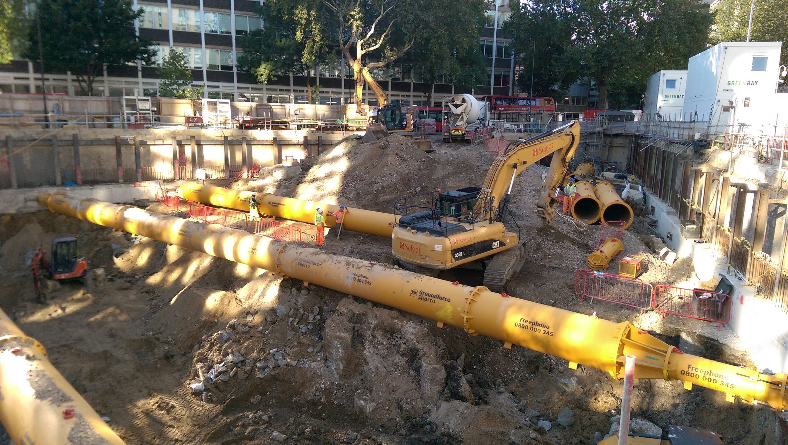
This week another capping beam pour took place, while a health and safety advisor was visiting and while the drainage order was being finalised.
Cost.
In reverse order, the drainage order included consideration of the attenuation tank which is to be situated below the basement level 2 slab. Company 1 was specified by the designer (or an approved alternative could be applied for) and therefore almost without question Company 1 were to be used. The QS team then got involved and got a quote from Company 2. A series of reasonably sensible RFIs from the designer followed (focussing on maintenance and strength of tank to resist earth pressures) and time started to disappear. Company 1 were informed about a second competitive quote and reduced their price. This meant that by simply asking the question of Company 1 they reduced their price saving a few thousand pounds.
Lesson Learnt? So other than saying it’s obvious to get a number of quotes, it is perhaps less obvious but equally commercially important to recognise when to challenge an expensive design, especially in a design and build contract. These smaller sub-contract packages are actually pretty key in the Design and Build contract arrangement. So far there have been about 10 sub-contractor packages ranging from sheet piling to attenuation tanks to concrete waterproofing supplier. So clearly a bit of effort getting quotes/bids from the market lots of cost savings can be gained from that which the initial project tender was based on. I here Steve’s bus…
Health and Safety/Quality.
Next comes the health and safety advisor’s visit. On a difficult day with machines breaking, particularly low consistence concrete (to gain high early strength) making pours difficult, a 5m deep excavation confining the site further and a muck away lorry to be loaded every 15 minutes, managing every activity was challenging.
This photo shows the ever decreasing space on site with muck away lorries needing to be loaded effectively non-stop all day.
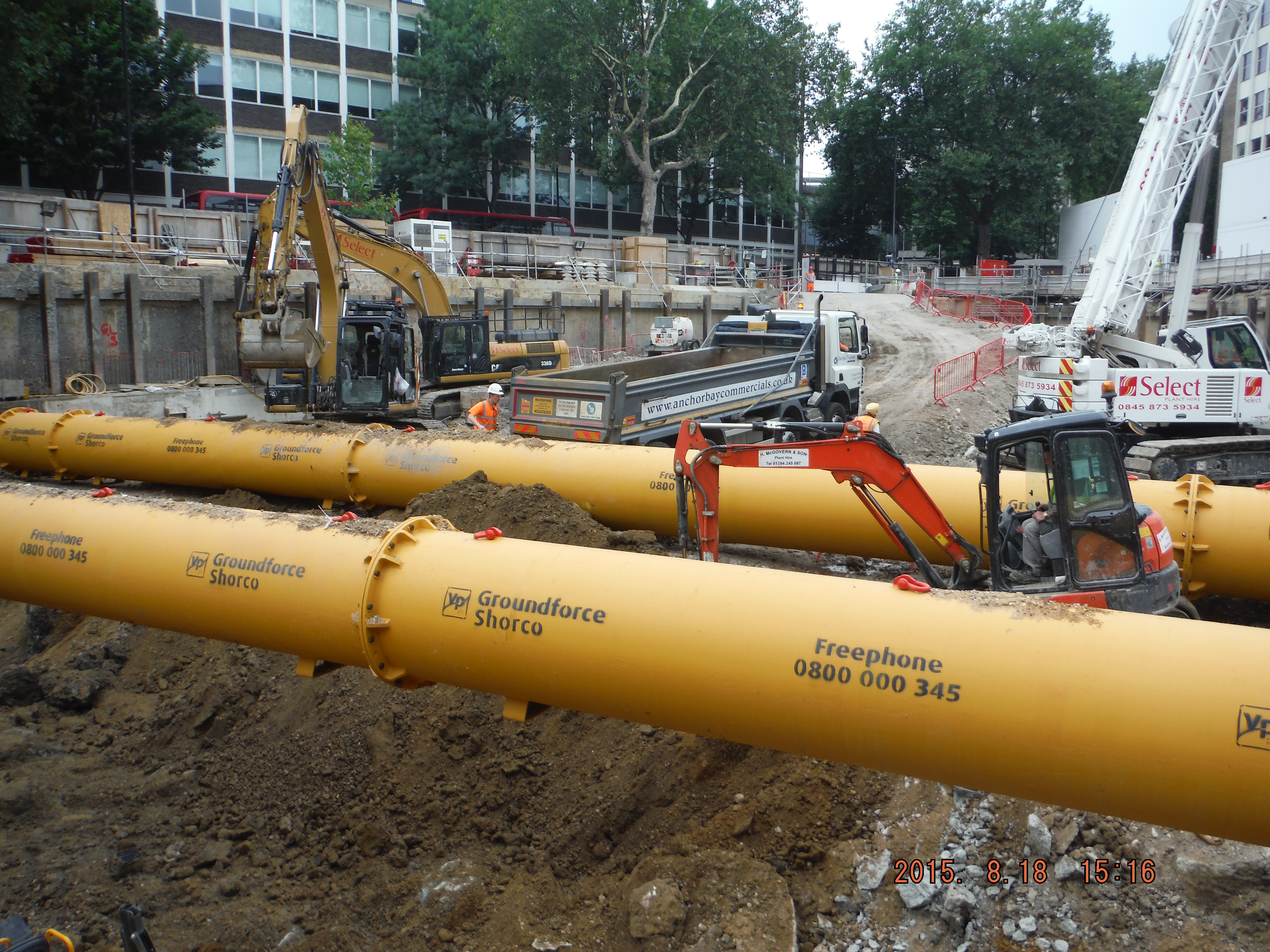
Props reducing site space

Crane at maximum reach.
Of the issues that could have been raised, the main one was access.
To get the formwork shuttering ready for the pour the focus had not been on access. When pointed out it is obvious and I suppose the lesson is: there are a few basics that must be correct and access is up there. The photo below the walkway barriers leading towards the concrete pour. It does not show that the walkway just ends in a 1m drop meaning the operatives had to scramble down the bank.
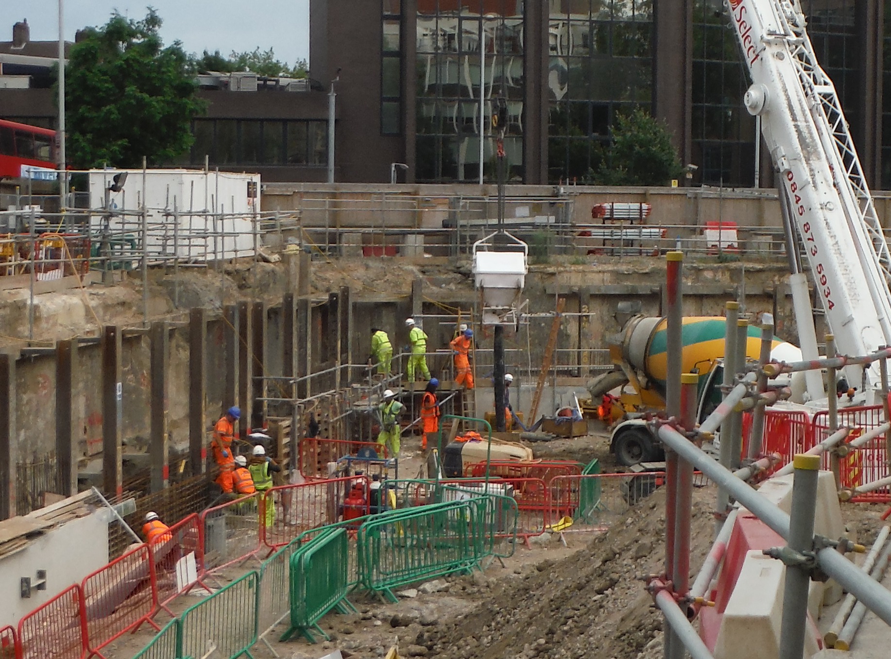
Barriers with no access at the end!
Time.
The capping beam has to be completed to be able to dig down. In order to do this the concrete strength within the capping beam must be greater than 30N/mm2. This would have been fine but due to a slow exit of the piling team we are on catch up.
So what? Capping beam pours have been completed and props installed shortly afterwards. With over 10,000m3 of sand, gravel and clay to be removed from the site the emphasis is on digging, i.e. loading the props and therefore loading the capping beam. In short, the time for the capping beam to reach 30N/mm2 has reduced from a few weeks to a few days. To solve this there were numerous plans to crush more cubes, do temperature matched curing and place thermocouples within the capping beam to assess in-situ strength. However there was no time to see what might happen/work, so the mix design was altered to attempt to get a quicker strength gain. (So much for previously trying to avoid cracking!)
Mix design alternations focussed on the cement content.
Original cement content: CEM 1: 135kg/m3 with GGBS: 315kg/m3.
High early strength concrete: CEM1: 405kg/m3 with GGBS: 45kg/m3.
Wowser! You could have fried an egg on the concrete. Basically the high cement content produced a very high early strength (about 41N/mm2 within 7 days). So despite there being a cost for the higher cement mix the key driver was time in order to get the excavation going, and therefore multiple work fronts to attempt to regain lost time.
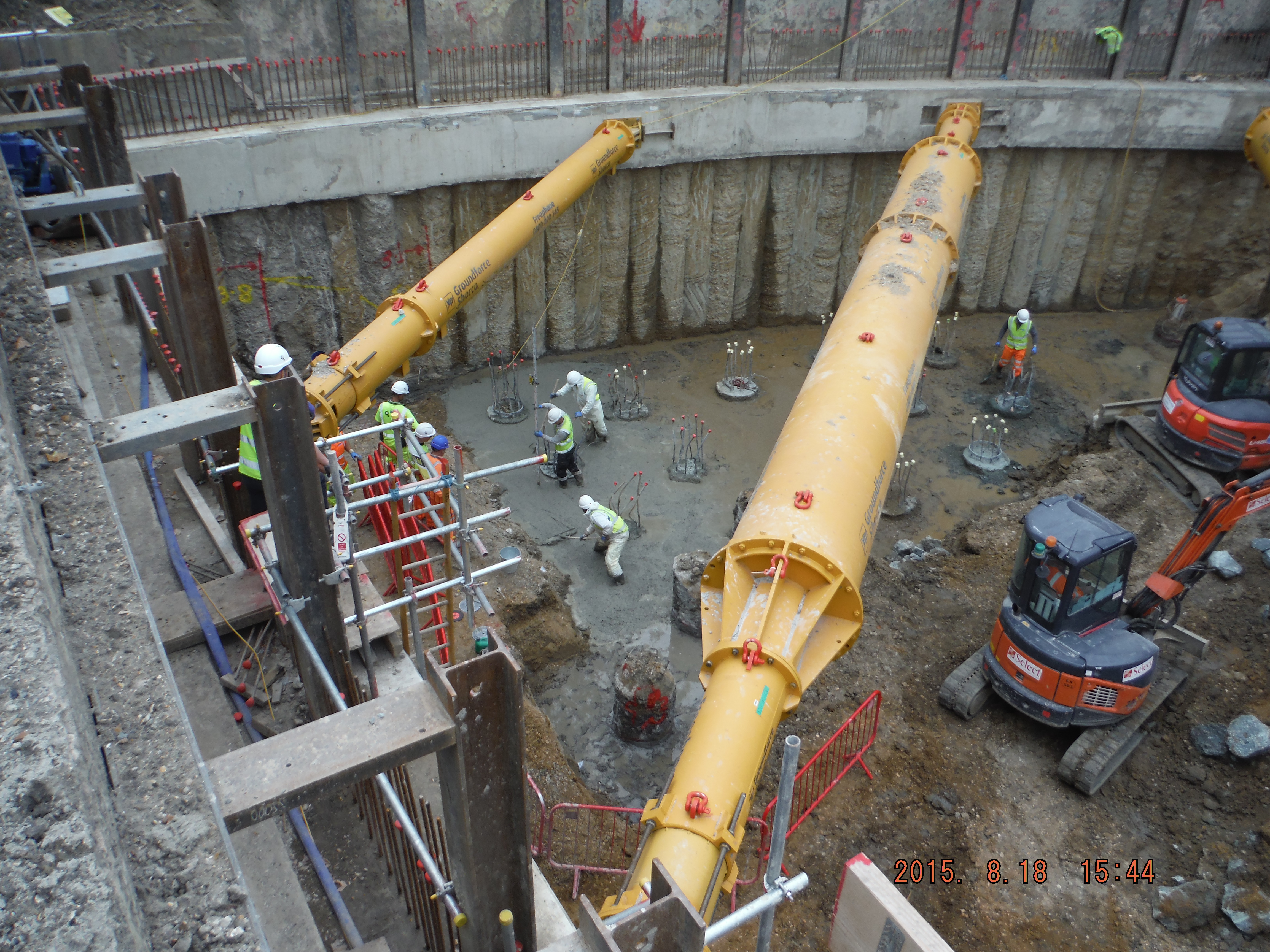
Capping beam fully loaded by props. Excavation needed to get going to prepare ground for raft slab pour.
Summary.
Every step of the way in the project revolves around time, cost and quality. I had a reasonable argument with the QS team saying that rather than faffing about getting quotes from everyone endangering getting items ordered in time, the focus should be on constructing the building. But then if the building costs more than £119 there will have been no point doing it for the contractor. So it seems the way forward is within the triangle, perhaps being at different corners at times, but it is a balance of time, cost and quality that is the key, which I think is wrapped in the word sustainable.
Yippie kay yay
I was planning on blogging about flushing and COA analysis for drainage, however, something much more interesting has cropped up today (in my opinion), so I’m afraid you’ll have to wait until next week for the car chase.
As a side note, before I start my blog, I’ve not seen any phase 1 students commenting on blogs on here. I know I was guilty of not commenting whilst on phase 1. If there is anything in particular that you want to know about on site, please let me know and I’ll try and tailor future blogs cover those topics.
I was always under the impression that 09.50 and 21.50 were cow-boy time. Not on BPSP1, its cow-boy time 24/7.
A few months ago I blogged about getting a temporary substation (TSS3) brought onto site. It has finally come to the stage when we’re going to connect TSS3 to the rest of the HV distribution network. This is to be done in two stages, initially TSS3 will be connected to TSS2 to create an even bigger radial. At a later date TSS3 will be connected to our DNO switch room to provide a ring main. This blog will focus on the first phase which is being conducted today.
In preparing for these works I reviewed the RAMS that were submitted by Wyse Power (our temporary electrical sub-contractor). After a bit of back and forth they were signed off at status A. This is an extract of part of the methodology:
1) Operatives will attend site for site specific induction as per the site rules.
2) Operative will read, understand and sign off this method statement and sign the back sheet.
3) The senior site operative (WP SAP & HVMS SAP) will carry out a site survey and POWRA– what risks will interface with works coordinate with site management and carry out a pre works check with all other WysePower operatives.
4) SAP (James Sherlock) to sign on and accept AP duties.
5) SAP to write up switching log and have approved by second SAP (Kevin Poole).
TSS2 to TSS3
6) SAP to carry out isolation and apply earth to SF6 Ring to TSS2 Ring Switch, fit safety lock and caution sign. SAP to fit danger sign to adjacent live equipment and HVMS SAP to witness. See ref 1 on schematic.
7) SAP to carry out isolation and apply earth to SF6 Ring to TSS3 Ring Switch, fit safety lock and caution sign. SAP to fit danger sign to adjacent live equipment and HVMS SAP to witness. See ref 2 on schematic.
8) SAP to confirm dead to jointing team.
9) SAP to issue permit to work for the connection of TSS3 to TSS2 SAP HMVS will hold the keys to the locks.
All pretty straight forward stuff. I spoke to the SAP yesterday and warned him off that as part of my education I’d like to come down and see how the above process worked in reality. The key part here is that Wyse Power knew that I was going to visit them. HVMS are a cable jointing firm who are being subcontracted by Wyse Power to connect the HV cable into the ring main units.
So what happened when I got to site?
Point 1 above- Complete
Point 2 – no RAMS on site and James confirmed to me that he hadn’t seen the RAMS. ARGHHHH!!!!!!
Point 3 – Complete
Point 4 – Not done.
Point 5 – No switching log present. The second SAP mentioned above is a project manager who is off site and therefore cannot sign the paperwork unless it was completed in advance.
Point 6 , 7, 8- Works not at this stage yet, but it was being discussed that padlocks be left off whilst the HVMS SAP went to get his own.
Point 7 – SNo permit to work produced.
Essentially the works being carried out are very basic, both the switches involved are already switched off and earthed and because of that the guys involved have got complacent. I had to stop the works, bring the SAP (James) up to my office and physically give him a copy of the RAMS, we then sat down and read through the RAMS. He then went away and produced all the necessary paperwork. We managed to get round the issue of the second SAP (Kevin who wasn’t on site) countersigning the switching log by virtue of the fact one of the HVMS workers was an SAP and was able to countersign.
All in all very simple to sort out, but hugely frustrating that I had to get involved in the first place.
Oz PCH – Fire & Smoke Management Cause & Effect: Technical and Commercial Issues.
Introduction
This blog highlights the commercial impact of a technical issue that can spread across many levels and affect multiple subcontractors/parties.
This could be yet another contracts management exam question.
It also covers next steps in fire cause and effect design development and testing and commissioning.
Issue
Reviewing the fire and smoke management cause and effect matrix highlighted some potential issues for the mechanical equipment; namely fans and dampers. Centigrade, mechanical fit-out subcontractor, had to install 72 x additional smoke dampers (electronically controlled) in various fire zones across the project. 10 x original dampers have been removed so the actual delta is 62. This was due to the initial design drawings by NDY, design consultancy, not reflecting departmental design changes.
Schneider, controls subcontractor, didn’t know about the additional dampers which now presents a serious technical issue; the ability to connect each new damper to a controls board. This throws up lots of detail like; have all the walls and ceilings in those areas been closed? Where is the connection point for the cables? Etc, etc.
Why didn’t Schneider know? Whose responsibility was it to inform them of the design change? From a technical stand point Centigrade has to have their new smoke damper design approved by NDY. Whether design consultants like to officially approve a third parties’ design is another matter; usually they don’t and won’t in case things go belly-up. However, they should at least review and comment on it. This design review information is then sufficient for them to either pass on to those who need to know about it; in this case Schneider, or at least inform the managing contractor, JHG; or ideally do both. So what actually happened? Nothing! This has led us, the commissioning team, to get involved in design – which clearly isn’t/shouldn’t be our remit. This situation reinforces NDY’s alternate acronym; Not Done Yet.
This type of ‘interface verification’ to use the commissioning vernacular for a scope gap between two or more subcontractor’s works meeting, seems to be a recurring issue in a number of areas across the project.
Solution
In order to find a technical/operational solution, to get the system working and to a commissionable state, we must now conduct a desktop study and understand exactly how many, including the exact location of the additional dampers, require wiring into Schneider control panels. Figure 1 was used to help explain how to go about this; splitting project areas into fire zones and then annotating drawing schematics with additional dampers to then understand the best possible wiring route to Schneider’s control panels. Figure 2 shows the cause and effect matrix as intended by NDY. It requires cross referencing against updated fire and smoke zones according to as-built architectural drawings. The trade contractors can then work through the detailed design of their individual dampers (smoke, fire, and smoke-fire). This then all needs to be reviewed and approved by NDY; which JHG will be insisting they sign-off on.
Figure 3 is the printed version which you can see is a pretty big beast. This is only the mechanical equipment with similar sized spreadsheets for miscellaneous equipment interfaces such as; hydraulics, lifts, medical gas, AGVs, security doors and PA alert system.
Figure 1. Smoke Damper Desktop Study Example.
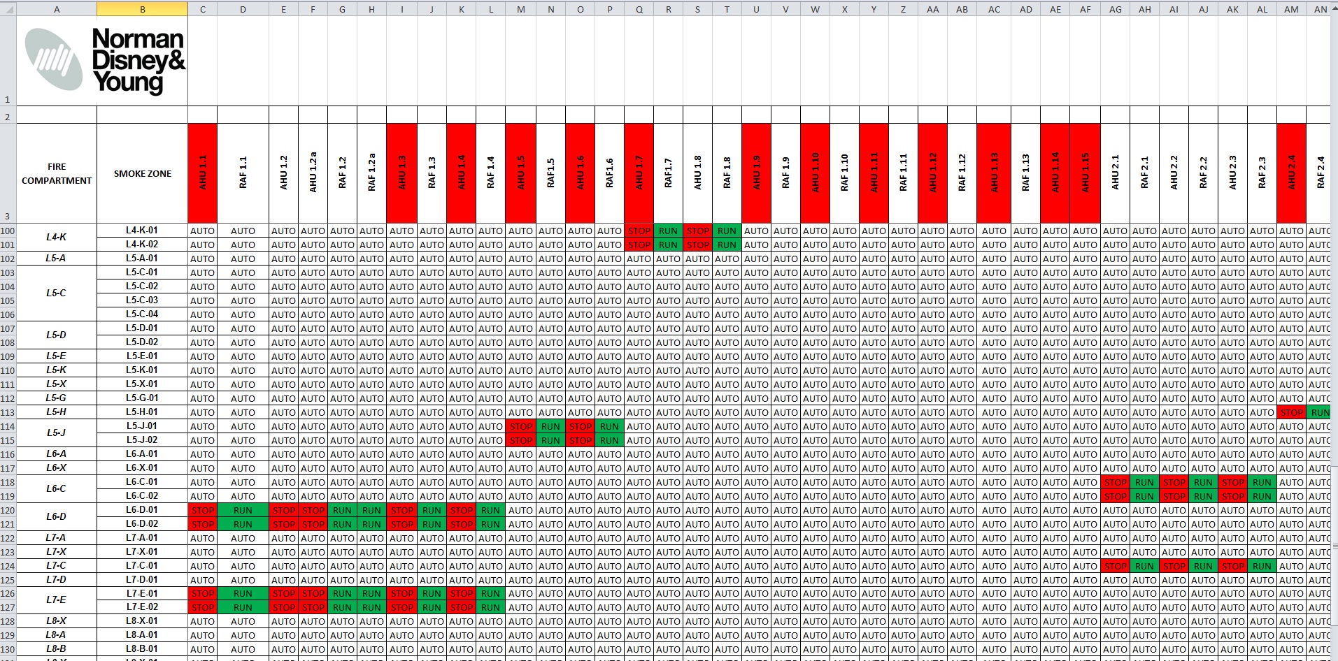
Figure 2. Excel Screen Shot of Fire Cause & Effect Matrix.

Figure 3. Print out of Fire Cause & Effect Matrix.
Commercial Implications
Commercially, this will open a can of worms; Centigrade will be putting in a variation order for their additional smoke damper design work; and Schneider will follow suit for their additional controls cable to said dampers. JHG will then no-doubt pass these straight to NDY as it was their inadequate design that caused the issue.
Playing devil’s advocate; NDY will most likely say the reason additional smoke dampers were required was because Fredon, plantroom mechanical fit-out subcontractor, changed the layout of some of their AHUs in the plantrooms. And here’s the irony; why do you think Fredon had to change the layout? Correct; because NDY also poorly designed that area too.
In terms of project contractual relationships; JHG being the managing contractor have a very ‘thin’ level of management that sits above the subcontractors and consultants (see figure 3). This means that issues of communication, as in this example and many others where subcontractors need to talk to each other, have to be managed carefully – which unfortunately on this project, due to the ‘thin’ level of management, isn’t all that great.
Figure 3. Contractual Relationships.
Design Development
The issue discussed above should have been solved months ago. Remembering we are in the testing and commissioning phase and our remit is to conduct just that, but we have found ourselves having to develop the design first. We have had to set up a workshop to ‘war game’ a few example areas to; a) prove NDY’s Cause and Effect Matrix, b) add in any additional dampers as a result of fire and smoke zonal changes and c) ensure these additional dampers get the required power/controls to operate. Once the subcontractors understand how to develop the design (which still lies with NDY), NDY will then review and approve.
Testing & Commissioning
This will involve using the revised cause and effect matrix to test each and every fire and smoke zone across all levels; a pretty mammoth task. Without going into too much detail, the detailed fire engineer design report stipulates test methodology and what pressures we need to be within. As outlined in the report and from AS 1668.1:1998 The use of ventilation and air-conditioning in buildings – Part 1: Fire and smoke control in multi-compartment building; it states “positive pressure not less than 20 Pa and not greater than 100 Pa shall be developed in all non-fire-affected zones above the pressure in the fire-affected zone…”
The air-conditioning system and controls interface aims to achieve this pressure gradient by a combination of; stopping the supply air and ramping the extract/return air in the fire-affected zone (to create negative pressure) and then ramp the supply air and stop the extract/return air in the adjacent non-fire-affected zones (creating positive pressure). The 100 Pa maximum is stipulated to ensure doors can be physically opened by escaping occupants. Figure 4 shows an example of the fire and smoke zone drawings being used in conjunction with the subcontractor’s shop drawings to identify the location and type of damper in place and establishing, using the cause and effect matrix, if the actual as-built layout can achieve the design intent. This was a dry run of how we intend to run our workshop.
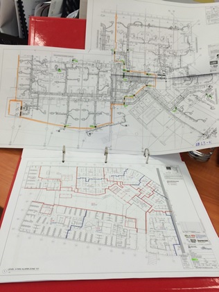
Figure 4. Fire and Smoke Zone Drawings and Subcontractor’s Layout Drawings.
Potential Issues
A number of issues can arise from the testing which I will blog about separately if and when encountered; if I’m not already on Phase 3 and here to witness them that is. Generally they will be things likes; can we achieve the 20 Pa min pressure drop across the fire zone doors? Can we rely on extract/exhaust alone to create the pressure gradient? This could be a requirement due to the outcome of integrated scenario testing where an electrical power failure has occurred, simultaneously with a fire starting. The back-up generator and UPS system will only provide power to essential and critical-essential supplies and not non-essential. Unfortunately, a number of the AHU supply fans are powered on the non-essential supply and so if lost to a power outage cannot play their part in zonal pressurisation. There will be other potential issues concerning building fabric air-tightness throughout the building but particularly regarding smoke walls that dissect a fire zone. These will have motorised smoke dampers but still require adequate sealing to avoid smoke spill. There will also no-doubt be other potential issues specific to certain areas of the building like staircase pressurisation and the like.
