Archive
Oz PCH – Chilled Water (CHW) Pipework Flushing.
Introduction
Usually once all CHW pipework has been installed in all plantrooms and throughout the whole network this is when the commissioning process of flushing and cleaning commences. However, on this project Central Communications Room 2 (CCR2), which houses all the communication equipment and creates a large heating load, was required to be switched on early. Therefore the heat load required to be controlled and cooled so the decision was made to use the intended CHW system to do this; however, there were a number of plantrooms still under construction with incomplete pipework. The work around was to shut off the isolation valves from the lower basement to the rest of the building and using the intended CHW main pump room (plantroom 10) flush and clean that part of the pipe network. This meant that we could then open up the isolation valves from the Central Energy Plant (CEP), which provides CHW to the entire Queen Elizabeth II Medical Centre (QE II MC) site, and provide the CHW required for CCR2.
So What?
In doing this and maintaining the CHW from the CEP through plantroom 10 to cool CCR2 it meant that when the remaining plantrooms and CHW pipework was finally installed that part of the network would have to be flushed and cleaned separately to avoid contaminating the lower basement pipework that has already been cleaned and is operational but more importantly avoid contaminating the CHW system from the CEP which also feeds the rest of the QE II MC site.
The Solution
It wasn’t possible to shut down CCR2 and so the only solution was to flush and clean the remainder of the network in bit-part fashion – not ideal or the way it should be done. Why? Because it meant that we could no longer use plantroom 10 main pumps and instead had to get the subcontractor (Fredon) to use a stand-alone flushing rig (with its own pump set). The intention would be to flush and clean each plantroom separately back to the point of the lower basement isolation valves.
The Issue
The first plantroom to be flushed (plantroom 7) was set-up with the flushing rig and ready to go when disaster struck. The armoured flexible coupling from the rig to the pipework had an epic fail and flooded the plantroom. Fredon informed us that the flexible hose burst off the flanged collar under the pressure (3 bar) and volume of water. BSIRA guidelines state:
The specified minimum flushing velocity should be that indicated in the table (figure 1), or the design velocity plus 10%, whichever is the greater. The flushing velocity must be selected based on the largest pipe size in the system or circuit to be flushed.
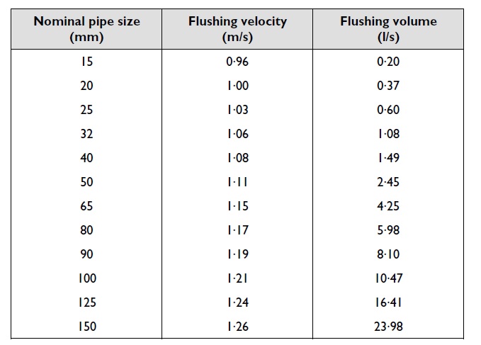
Figure 1. Minimum water velocities required to move 5 mm diameter steel particles in horizontal medium grade steel pipework (BSRIA).
So for a pipe diameter of 150 mm the flushing velocity should be 1.26 m/s with a flow rate of 24 l/s to flush out a particle size of 5 mm in diameter. The test rig was actually set at 27 l/s which equates to 1.42 m/s (at 150 mm pipe) which is over the velocity in the figure 1 table. Figure 2 shows the flushing rig and figure 2 the rig’s flanged connection end and butterfly isolation valve.
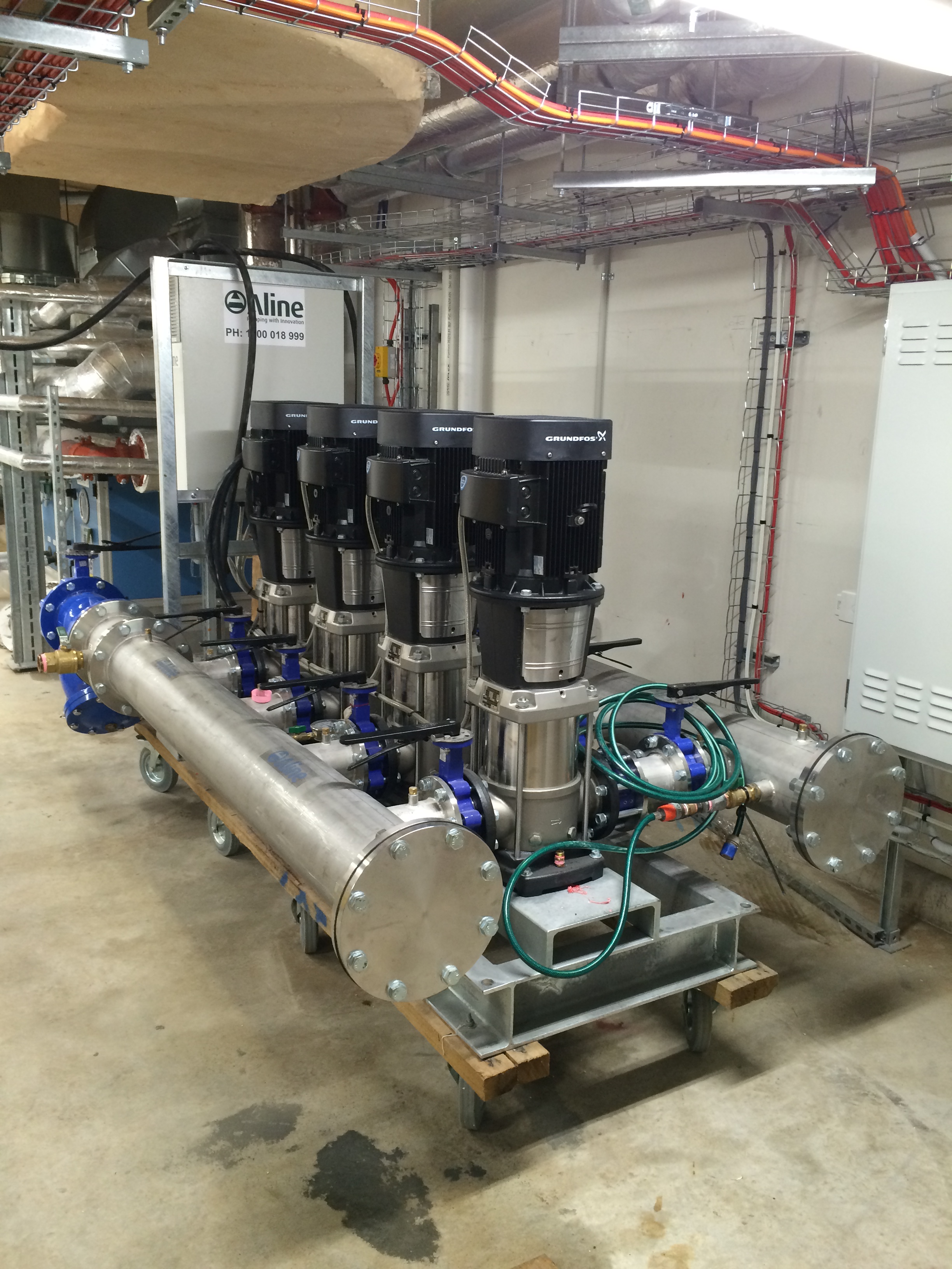
Figure 2. Fredon’s Flushing Rig.
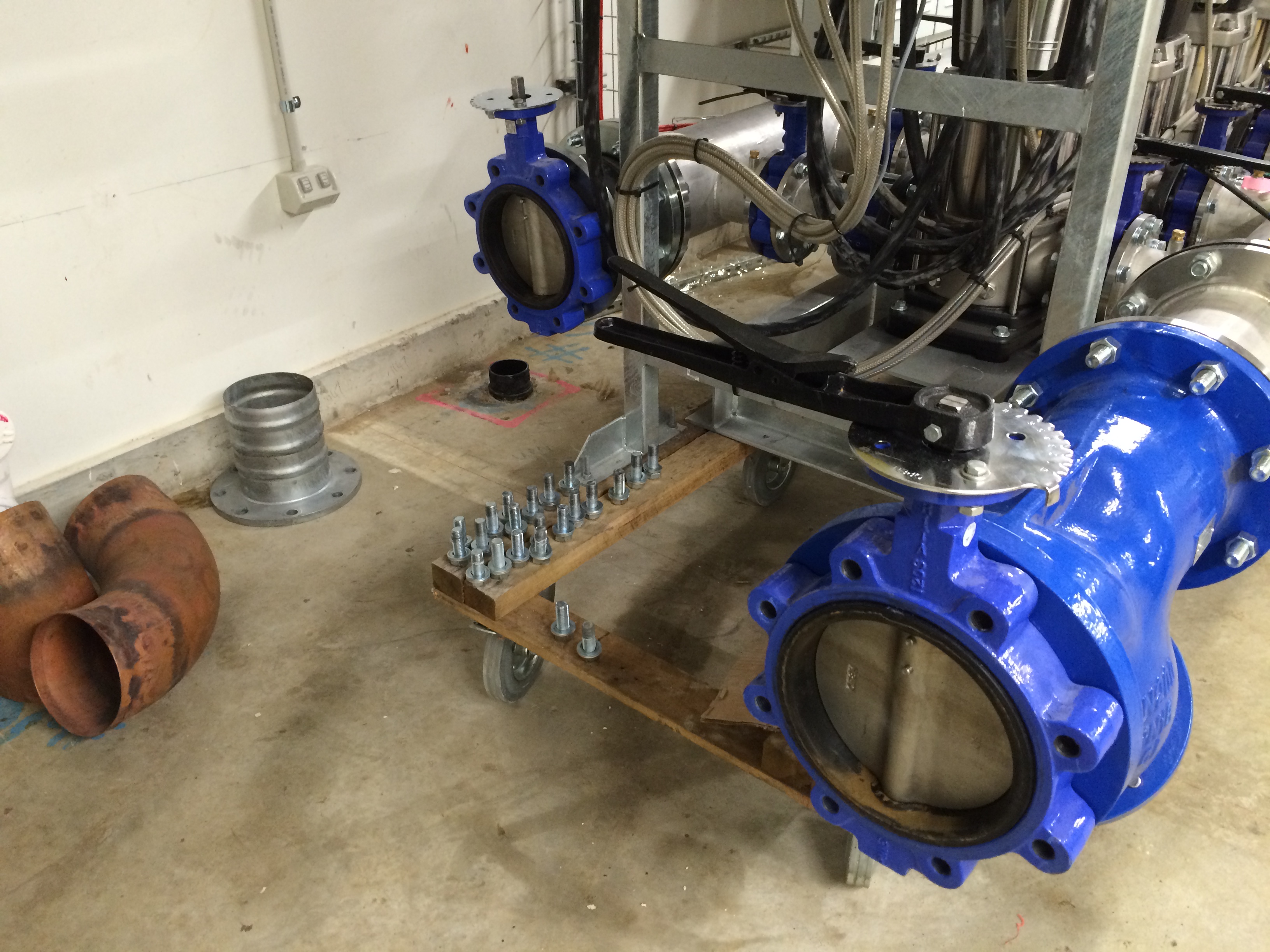
Figure 3. Flushing Rig Flanged Isolation Valve.
Fredon say that the two securing bands (like a large jubilee clip) must not have been tight enough as supplied by the hose manufacturer and under the weight and pressure of the water bust it off the collar. You can see the collar in figure 3 (circled red) but the hose had already been removed from site to be tested where it can’t do any more damage. Fredon gave it another go, after tightening the bands, but it popped off again. Their solution was to use a ‘hard’ coupling using 200 mm diameter copper pipe (figure 4). This removes the flexibility and ease of connection to the rig and means that until the flexi hose is proved fit for purpose every plantroom will most likely need a separate set of copper coupling dependant on the network connection outlet heights and accessibility – hence the preferred flexi hose method. Figure 5 shows the network connection flow and return points reducing from 200 mm rig pipe diameter to 150 mm system pipe diameter.
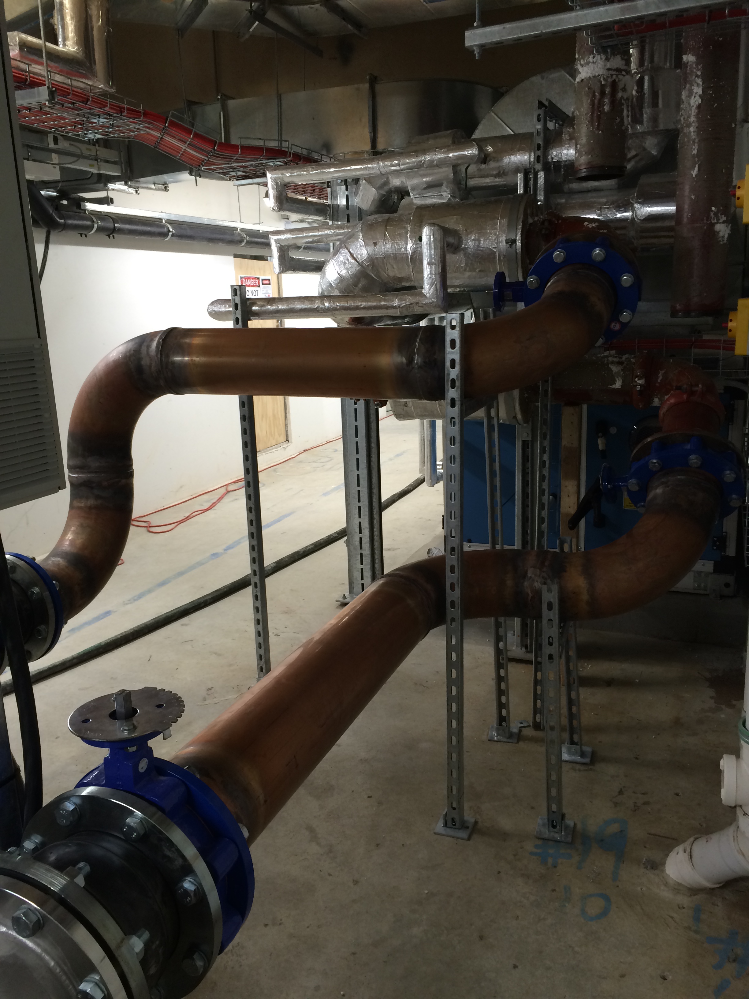
Figure 4. Rig Hard Copper Coupling.
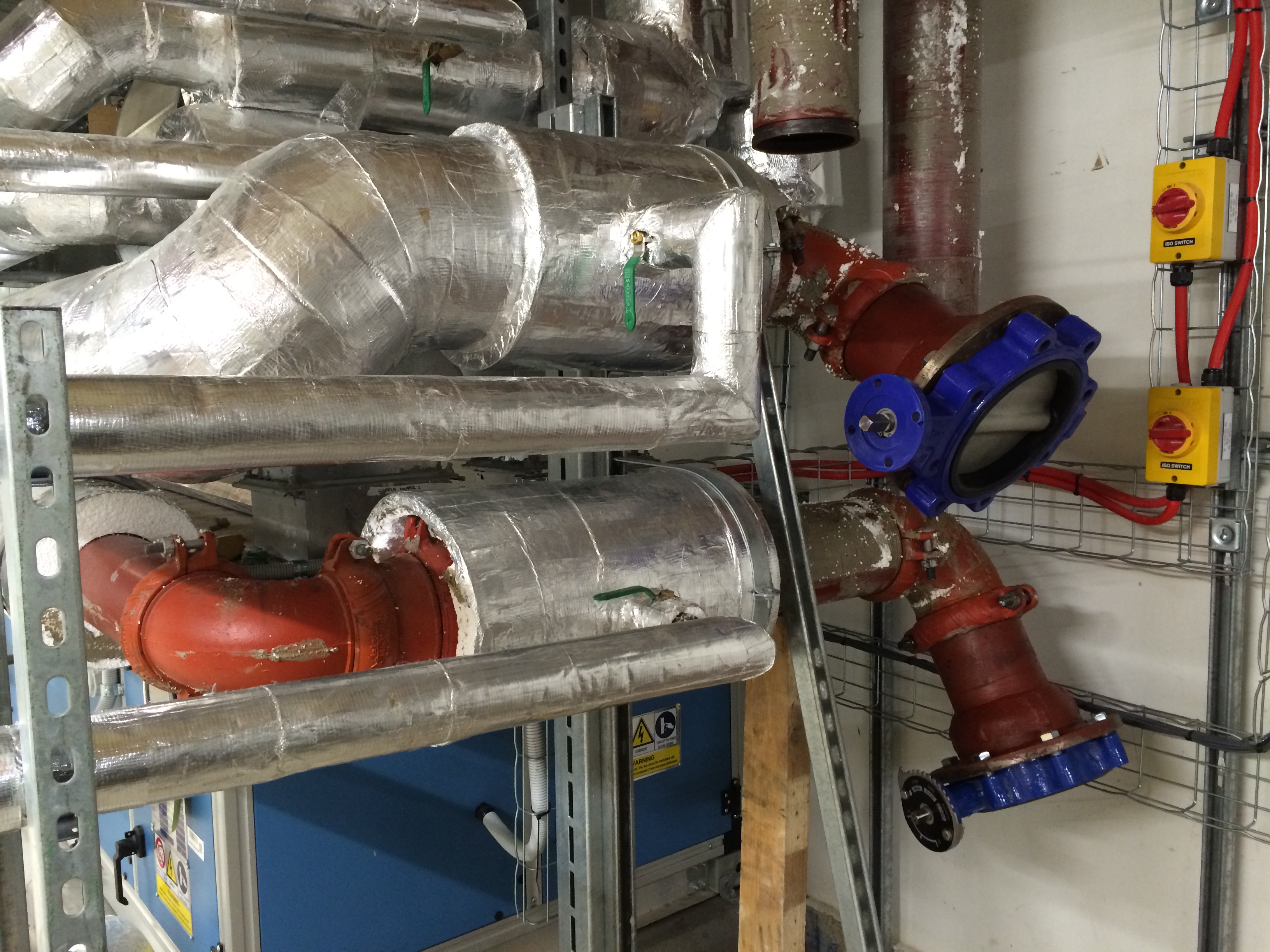
Figure 5. Plantroom Network Connection Points.
The Damage
Figure 6 – 8 shows the damage caused from the flooding. It doesn’t look like much but water being water will find its way into every gap possible. To add insult to injury the plantrooom floor hadn’t yet been sealed water tight so water ran between the gaps where, ironically, the drainage pipework stacks are fitted into the concrete slab and came through to the ceiling of the level below damaging some ceiling tiles and insulation.
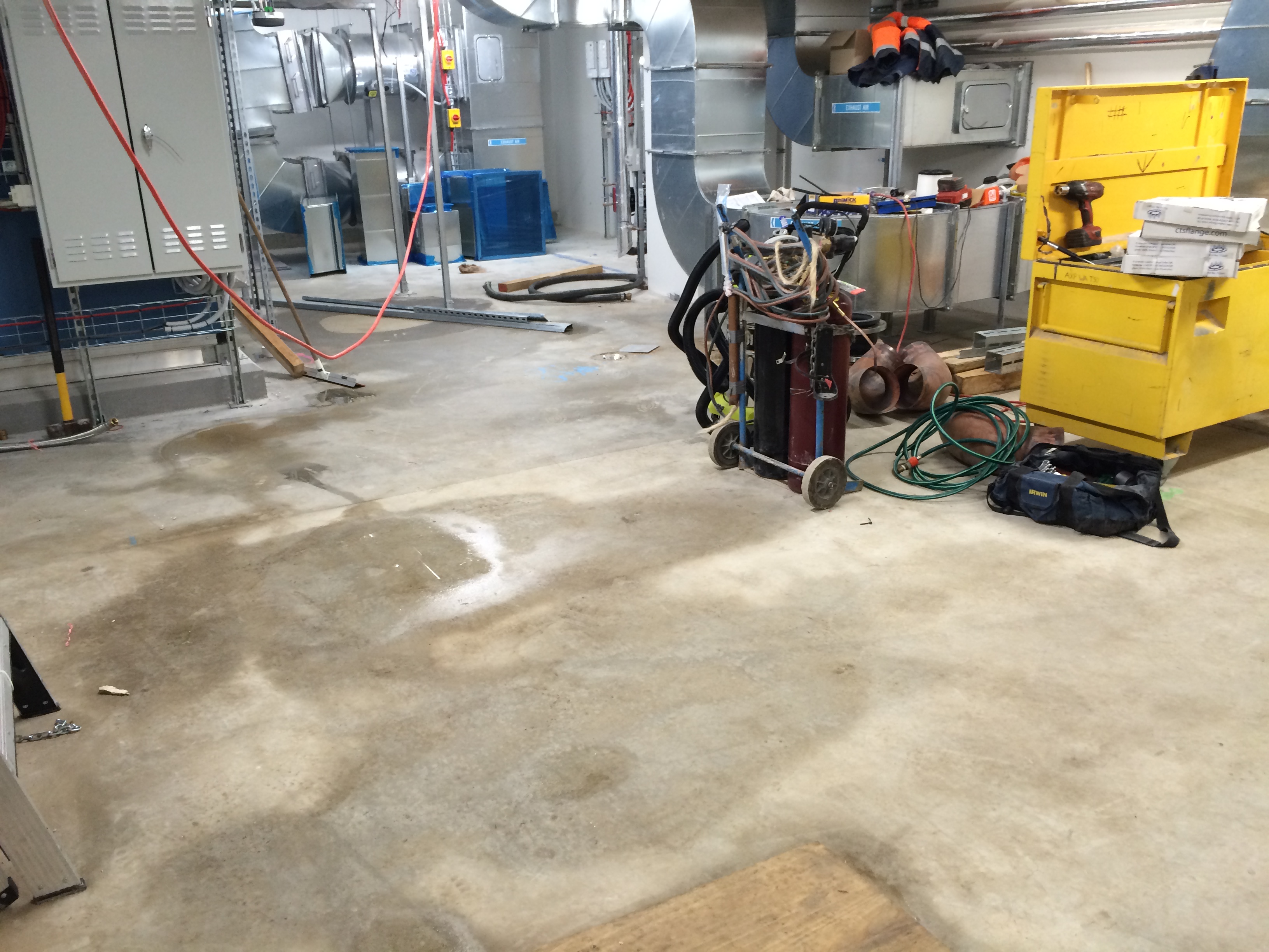
Figure 6. Plantroom 7 Water Damage.

Figure 7. Drainage Stacks.
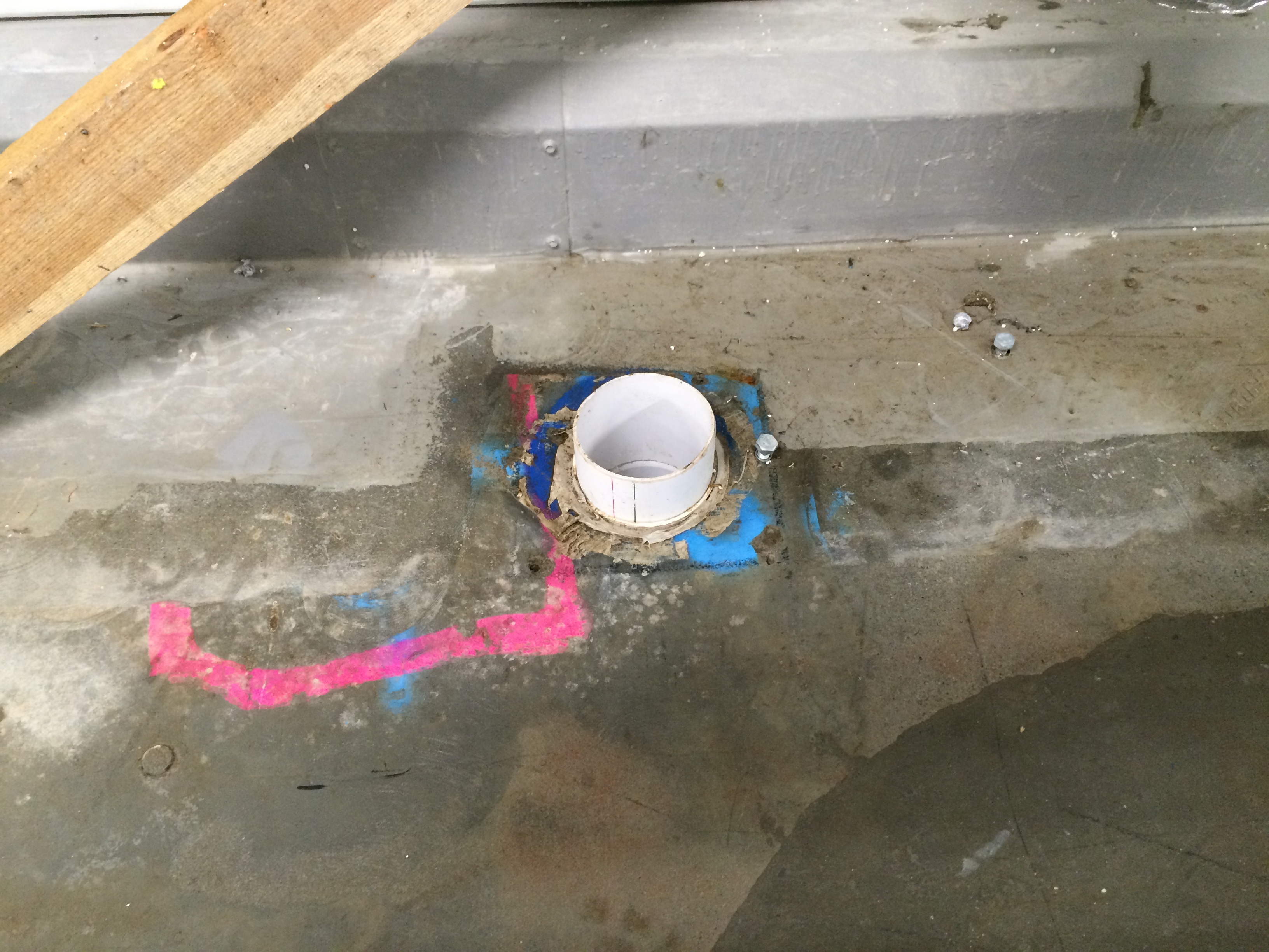
Figure 8. Tundish Drainage from AHU.
Additional Potential Issues
There are also potential issues of someone accidently opening an isolation valve between a plantroom and a riser feeding into the lower basement circuit and therefore, if not flushed will contaminate the CEP.
A second order affect is the Floor Control Rooms (FCRs) which house some IT infrastructure. They aren’t operating at full capacity yet so only a small percentage of the heating load is being seen. Due to this small load these areas still need to be kept cool and so the FCRs on the floors that have CHW supplied are flowing through Fan Coil Units (FCUs). The issue is that because the BMS is not yet fully operational the motorised control valve fitted to each FCU cannot be adjusted. And even with the double regulating valve of each leg manually turned down to the minimum setting the CHW in the FCU is around 6 ºC. So What? This is causing condensation issues where the temperature in the FCR is getting close to the Apparatus Dew Point (ADP) of around 14 – 15 ºC and compounded by the high humidity as the external façade hasn’t been installed in that area yet. This will only get worse when the outside temperature begins to rise and cause an even greater ∆T between the FCR and outside. The condensation could build to the point where it forms bigger water droplets and drips onto the IT eqpt thus potentially damaging it. Therefore this requires swift resolution; most likely in the form of either getting the BMS up and running or introducing temporary heating.
Conclusion
At the heart of both of these issues was commissioning the CHW system in bit-part and not all off the main pumps in one go. However, it was deemed more important to get the CHW system partly operational to cool CCR2. I would have thought another way of providing cooling could have been done through temporary FCUs placed in CCR2. Another conclusion is that floors should be water sealed prior to any pressure testing or flushing in order to limit damage caused by potential leaks. This issue also highlighted that there should have been localised bunding put in place like there is in other plantrooms. Consequentially Fredon’s flexi hose failed its off-site pressure test and so they have continued to use the copper hard coupling throughout the remaining flushing of plantrooms across the project.
