Archive
Yippie kay yay
I was planning on blogging about flushing and COA analysis for drainage, however, something much more interesting has cropped up today (in my opinion), so I’m afraid you’ll have to wait until next week for the car chase.
As a side note, before I start my blog, I’ve not seen any phase 1 students commenting on blogs on here. I know I was guilty of not commenting whilst on phase 1. If there is anything in particular that you want to know about on site, please let me know and I’ll try and tailor future blogs cover those topics.
I was always under the impression that 09.50 and 21.50 were cow-boy time. Not on BPSP1, its cow-boy time 24/7.
A few months ago I blogged about getting a temporary substation (TSS3) brought onto site. It has finally come to the stage when we’re going to connect TSS3 to the rest of the HV distribution network. This is to be done in two stages, initially TSS3 will be connected to TSS2 to create an even bigger radial. At a later date TSS3 will be connected to our DNO switch room to provide a ring main. This blog will focus on the first phase which is being conducted today.
In preparing for these works I reviewed the RAMS that were submitted by Wyse Power (our temporary electrical sub-contractor). After a bit of back and forth they were signed off at status A. This is an extract of part of the methodology:
1) Operatives will attend site for site specific induction as per the site rules.
2) Operative will read, understand and sign off this method statement and sign the back sheet.
3) The senior site operative (WP SAP & HVMS SAP) will carry out a site survey and POWRA– what risks will interface with works coordinate with site management and carry out a pre works check with all other WysePower operatives.
4) SAP (James Sherlock) to sign on and accept AP duties.
5) SAP to write up switching log and have approved by second SAP (Kevin Poole).
TSS2 to TSS3
6) SAP to carry out isolation and apply earth to SF6 Ring to TSS2 Ring Switch, fit safety lock and caution sign. SAP to fit danger sign to adjacent live equipment and HVMS SAP to witness. See ref 1 on schematic.
7) SAP to carry out isolation and apply earth to SF6 Ring to TSS3 Ring Switch, fit safety lock and caution sign. SAP to fit danger sign to adjacent live equipment and HVMS SAP to witness. See ref 2 on schematic.
8) SAP to confirm dead to jointing team.
9) SAP to issue permit to work for the connection of TSS3 to TSS2 SAP HMVS will hold the keys to the locks.
All pretty straight forward stuff. I spoke to the SAP yesterday and warned him off that as part of my education I’d like to come down and see how the above process worked in reality. The key part here is that Wyse Power knew that I was going to visit them. HVMS are a cable jointing firm who are being subcontracted by Wyse Power to connect the HV cable into the ring main units.
So what happened when I got to site?
Point 1 above- Complete
Point 2 – no RAMS on site and James confirmed to me that he hadn’t seen the RAMS. ARGHHHH!!!!!!
Point 3 – Complete
Point 4 – Not done.
Point 5 – No switching log present. The second SAP mentioned above is a project manager who is off site and therefore cannot sign the paperwork unless it was completed in advance.
Point 6 , 7, 8- Works not at this stage yet, but it was being discussed that padlocks be left off whilst the HVMS SAP went to get his own.
Point 7 – SNo permit to work produced.
Essentially the works being carried out are very basic, both the switches involved are already switched off and earthed and because of that the guys involved have got complacent. I had to stop the works, bring the SAP (James) up to my office and physically give him a copy of the RAMS, we then sat down and read through the RAMS. He then went away and produced all the necessary paperwork. We managed to get round the issue of the second SAP (Kevin who wasn’t on site) countersigning the switching log by virtue of the fact one of the HVMS workers was an SAP and was able to countersign.
All in all very simple to sort out, but hugely frustrating that I had to get involved in the first place.
Oz PCH – Fire & Smoke Management Cause & Effect: Technical and Commercial Issues.
Introduction
This blog highlights the commercial impact of a technical issue that can spread across many levels and affect multiple subcontractors/parties.
This could be yet another contracts management exam question.
It also covers next steps in fire cause and effect design development and testing and commissioning.
Issue
Reviewing the fire and smoke management cause and effect matrix highlighted some potential issues for the mechanical equipment; namely fans and dampers. Centigrade, mechanical fit-out subcontractor, had to install 72 x additional smoke dampers (electronically controlled) in various fire zones across the project. 10 x original dampers have been removed so the actual delta is 62. This was due to the initial design drawings by NDY, design consultancy, not reflecting departmental design changes.
Schneider, controls subcontractor, didn’t know about the additional dampers which now presents a serious technical issue; the ability to connect each new damper to a controls board. This throws up lots of detail like; have all the walls and ceilings in those areas been closed? Where is the connection point for the cables? Etc, etc.
Why didn’t Schneider know? Whose responsibility was it to inform them of the design change? From a technical stand point Centigrade has to have their new smoke damper design approved by NDY. Whether design consultants like to officially approve a third parties’ design is another matter; usually they don’t and won’t in case things go belly-up. However, they should at least review and comment on it. This design review information is then sufficient for them to either pass on to those who need to know about it; in this case Schneider, or at least inform the managing contractor, JHG; or ideally do both. So what actually happened? Nothing! This has led us, the commissioning team, to get involved in design – which clearly isn’t/shouldn’t be our remit. This situation reinforces NDY’s alternate acronym; Not Done Yet.
This type of ‘interface verification’ to use the commissioning vernacular for a scope gap between two or more subcontractor’s works meeting, seems to be a recurring issue in a number of areas across the project.
Solution
In order to find a technical/operational solution, to get the system working and to a commissionable state, we must now conduct a desktop study and understand exactly how many, including the exact location of the additional dampers, require wiring into Schneider control panels. Figure 1 was used to help explain how to go about this; splitting project areas into fire zones and then annotating drawing schematics with additional dampers to then understand the best possible wiring route to Schneider’s control panels. Figure 2 shows the cause and effect matrix as intended by NDY. It requires cross referencing against updated fire and smoke zones according to as-built architectural drawings. The trade contractors can then work through the detailed design of their individual dampers (smoke, fire, and smoke-fire). This then all needs to be reviewed and approved by NDY; which JHG will be insisting they sign-off on.
Figure 3 is the printed version which you can see is a pretty big beast. This is only the mechanical equipment with similar sized spreadsheets for miscellaneous equipment interfaces such as; hydraulics, lifts, medical gas, AGVs, security doors and PA alert system.
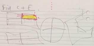
Figure 1. Smoke Damper Desktop Study Example.
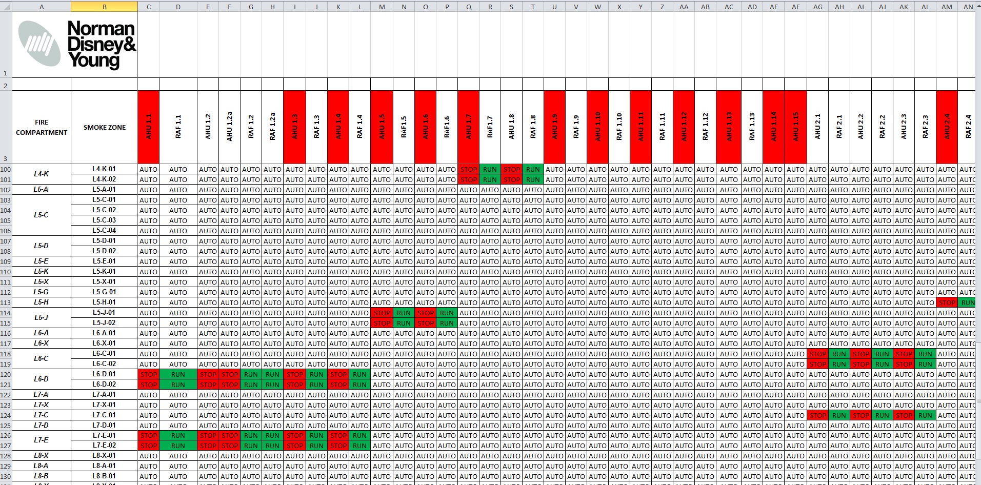
Figure 2. Excel Screen Shot of Fire Cause & Effect Matrix.

Figure 3. Print out of Fire Cause & Effect Matrix.
Commercial Implications
Commercially, this will open a can of worms; Centigrade will be putting in a variation order for their additional smoke damper design work; and Schneider will follow suit for their additional controls cable to said dampers. JHG will then no-doubt pass these straight to NDY as it was their inadequate design that caused the issue.
Playing devil’s advocate; NDY will most likely say the reason additional smoke dampers were required was because Fredon, plantroom mechanical fit-out subcontractor, changed the layout of some of their AHUs in the plantrooms. And here’s the irony; why do you think Fredon had to change the layout? Correct; because NDY also poorly designed that area too.
In terms of project contractual relationships; JHG being the managing contractor have a very ‘thin’ level of management that sits above the subcontractors and consultants (see figure 3). This means that issues of communication, as in this example and many others where subcontractors need to talk to each other, have to be managed carefully – which unfortunately on this project, due to the ‘thin’ level of management, isn’t all that great.
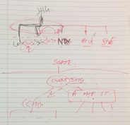
Figure 3. Contractual Relationships.
Design Development
The issue discussed above should have been solved months ago. Remembering we are in the testing and commissioning phase and our remit is to conduct just that, but we have found ourselves having to develop the design first. We have had to set up a workshop to ‘war game’ a few example areas to; a) prove NDY’s Cause and Effect Matrix, b) add in any additional dampers as a result of fire and smoke zonal changes and c) ensure these additional dampers get the required power/controls to operate. Once the subcontractors understand how to develop the design (which still lies with NDY), NDY will then review and approve.
Testing & Commissioning
This will involve using the revised cause and effect matrix to test each and every fire and smoke zone across all levels; a pretty mammoth task. Without going into too much detail, the detailed fire engineer design report stipulates test methodology and what pressures we need to be within. As outlined in the report and from AS 1668.1:1998 The use of ventilation and air-conditioning in buildings – Part 1: Fire and smoke control in multi-compartment building; it states “positive pressure not less than 20 Pa and not greater than 100 Pa shall be developed in all non-fire-affected zones above the pressure in the fire-affected zone…”
The air-conditioning system and controls interface aims to achieve this pressure gradient by a combination of; stopping the supply air and ramping the extract/return air in the fire-affected zone (to create negative pressure) and then ramp the supply air and stop the extract/return air in the adjacent non-fire-affected zones (creating positive pressure). The 100 Pa maximum is stipulated to ensure doors can be physically opened by escaping occupants. Figure 4 shows an example of the fire and smoke zone drawings being used in conjunction with the subcontractor’s shop drawings to identify the location and type of damper in place and establishing, using the cause and effect matrix, if the actual as-built layout can achieve the design intent. This was a dry run of how we intend to run our workshop.
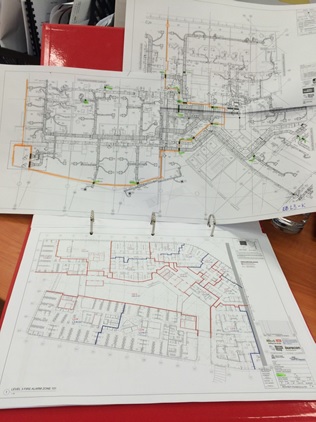
Figure 4. Fire and Smoke Zone Drawings and Subcontractor’s Layout Drawings.
Potential Issues
A number of issues can arise from the testing which I will blog about separately if and when encountered; if I’m not already on Phase 3 and here to witness them that is. Generally they will be things likes; can we achieve the 20 Pa min pressure drop across the fire zone doors? Can we rely on extract/exhaust alone to create the pressure gradient? This could be a requirement due to the outcome of integrated scenario testing where an electrical power failure has occurred, simultaneously with a fire starting. The back-up generator and UPS system will only provide power to essential and critical-essential supplies and not non-essential. Unfortunately, a number of the AHU supply fans are powered on the non-essential supply and so if lost to a power outage cannot play their part in zonal pressurisation. There will be other potential issues concerning building fabric air-tightness throughout the building but particularly regarding smoke walls that dissect a fire zone. These will have motorised smoke dampers but still require adequate sealing to avoid smoke spill. There will also no-doubt be other potential issues specific to certain areas of the building like staircase pressurisation and the like.
