Gut Feeling
Pre-amble
First I must apologise for not blogging for so long, as I’m sure you’re all on the edge of your seats waiting for my next instalment; I should have listened to those who warned me about parenthood!
This blog is regarding the design of a previously discussed project and conveniently reinforces what both Damo and Guz have just blogged about.
The Project – ETAP Lifeboat Maintenance Padeyes
Each of the 3 lifeboats on ETAP are lowered using a pair of winch cables attached forward and aft. The cable release mechanisms are sufficiently delicate that carrying out maintenance on the lifeboats requires maintenance strops to be used in order to provide a secure fixing to the structure in case of a release mechanism failure (size 10 boot). Due to new lifeboats being installed a couple of years ago, the maintenance padeyes are now considered under sized and out of alignment to the boat fixing locations. See figs 1 & 2.
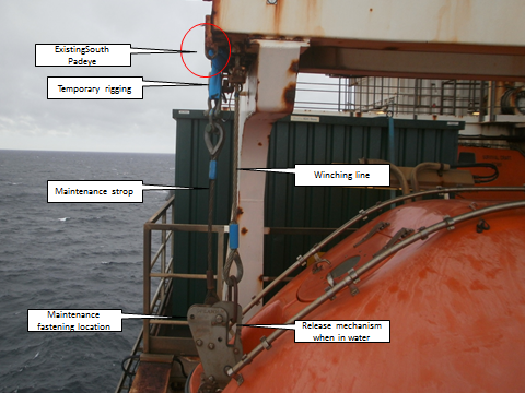
Fig 1 – Existing South padeye

Fig 2 – Existing North padeye
The original solution
The solution was simple. Cut off the existing padeyes and weld new, uprated padeyes in new locations. See fig 3 & 4.

Fig 3 – Proposed South padeye

Fig 4 – Proposed North padeye
So what’s the problem?
This project has been ‘hanging around’ for some time and hasn’t really moved forward, not helped by the ever changing personalities (see future blog). Following a couple of meetings back in June, the BP Offshore Execution Lead expressed concern that ‘it just doesn’t feel right’ and although I agreed with him, I just put it down to being new, as well as accepting that circa £100k had already been spent getting this project through the design phase so far, surely it must be right?
The following were highlighted as being a concern;
- It was understood from handover that the lifeboats would remain in service. The plan requires a significant amount of scaffolding around each lifeboat which by virtue of the restrictions, takes the lifeboat out of service.
- The plan had all 3 lifeboats being worked on at the same time. This just wouldn’t happen due to the obvious sensitive nature of the lifeboats.
- The plan required an amount of hot works (grinding/cutting & welding). Although the lifeboats were not in an area which required additional measures to be taken (use of a habitat, for example), there was still a risk to the lifeboats themselves and layers of protection would be required; reinforcing point 1 above.
- The padeyes would require testing once welded in position. The plan used a jig that wrapped around the davit structure see fig 5, so that the forces would be self-contained and not add to the davit arms themselves. This required both heavy and awkward lifting above a lifeboat and inches from the edge of the platform.

Fig 5 – Test rig
The solution
Following a ‘deep dive’ an alternative idea was suggested which was solely a bolted design, see figs 6 & 7.

Fig 6 – New North padeye design
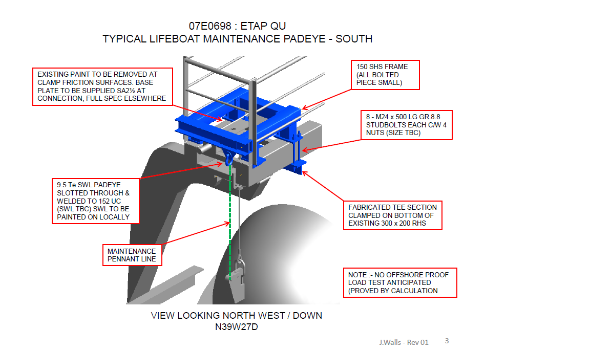
Fig 7 – New South padeye design
This design had the following benefits
1. No hot works are required which means less protection and less scaffolding reqd, which leads to a quicker install and a shorter time to get the lifeboat back into service.
2. Potential to construct using rope access only from the platform above. This would mean no scaffolding reqd and potentially reduce costs.
3. The entire frame could be proof tested onshore using a mock up davit arm/frame, and then re-assembled offshore.
So why wasn’t this option considered in the first place during the Appraise/Select phases?
It was, but as I understand it, was not selected because it did not look aesthetically pleasing!
Now what?
I am expecting a Project Change Notification (PCN) of between £50-100k to get this re-designed and ready for offshore construction, and potentially a delay to the ‘ready for construction’ date.
Conclusion
Even though a significant amount of time and resources had been spent on designing the solution, it does not mean it’s necessarily the right one. If it doesn’t feel right, it’s worth doing a ‘down, test and adjust’ to make sure the direction of travel is the right one, especially if the project has sat idle for some time and/or the entire team had changed.
This project is, technically, as simple as it gets. But from this blog and my previous, you will see that it is not straight forward and often it is the ‘so whats’ surrounding the project which add most of the complexities and frustrations.
In other news
Currently planning for phase 2 of the Grand Design, which incorporates replacing the boiler (expect a separate blog on this), getting drawings done for proposed extension and getting the final 2 rooms ready for move in. Pics to follow.

Mike, with the continuing drop in the price of Brent Crude are your sensing that work is starting to dry up for your department?
Jim,
Funny you should ask that, wait out, because last night I started drafting a blog on that exact topic!!
“It did not look aesthetically pleasing”, do you employ architects on oil rigs? Whose decision was that? Someone whose comfort zone was previous solutions involving welding?
Rich, It was the SPA (single point of Accountability) I took over from. That individual no longer works for BP.
Mike,
What is the test? I can’t make it out from the rig. Is it just to apply a test load to it? Is it part of Offshore standards?
Have you been reading your blogs to Matthew again?
Henry,
The test is simply a load test in the direction it would experience in normal conditions.
Confirming the actual value for the proof load to be used has been somewhat of a struggle as Lloyds Register are used to verify a lot of what we do, and trying to get clear unambiguous answer from them has been challenging! (see previous blog).
Yes there are regulations, and in this case we use the Code for Lifting in A Marine Environment (CLAME) which stipulates a Proof Load of 1.5*SWL and calculations to prove 4.5*SWL is below the UTS. Although those numbers are written in black and white, the wording can be interpreted different ways (and indeed was between different Lloyds personnel) and it was vital we got this agreed by them. What they didn’t do was tell us what the SWL was and left that for us to decide.
With reference to your second comment – no