Archive
Writing a schedule that helps you get paid.
Safe in the knowledge that everyone will be too busy fawning after Mike’s baby…
I just reviewed the FtIG boiler project schedule, again. Now, on version 4, the contractor has lowered my expectations sufficiently that I am now focused only on the money. Their timings for installing pipe work are unrealistically short and everything appears to be on the critical path. These, though annoying, are their problem as the contractor is responsible to ensure there is no gap in service for hot water, heating or cooling within certain seasons.
So resigned to failure on the time side I have turned to look at the money. USACE pay for definable elements, rather than the alternative of paying for percentage complete on the whole job. From the pay reviews that I have conducted for the Waste Water Treatment Plant this appears to be a better form of holding the contractor to account for finishing up individual elements. By paying 98% of an element that isn’t quite finished it leaves a virtual snagging list in dollars. These are more likely to be completed by the next pay period rather than being forgotten until the end of the project, when especially if there is a staff turnover, they get swept under the rug. We will pay for stored materials but, it has to be a significant element, the contractor has to show ownership and we prefer if it at least in place. For this project the boilers and water heaters may come into this but certainly nothing else. Again, for the waste water treatment plant we have paid for stored materials for a $60k generator and a $130k pump set so that really sets the magnitude. I’d be interested to hear what everybody else’s clients’ are happy to pay for on that?
So what’s my issue with the FtIG values? I have two:
To me definable elements are like a product breakdown structure (PBS) and when it comes to pay time I want to be able to go to the element, look at it, tick a box and pay the contractor. This is not me being an idle box ticker rather ensuring that each element is well defined, and I assume this will help them with their sub-contractors. The FtIG programme has not been built from a PBS so I can foresee the arguments coming at pay time. The lesson from this is do a detailed PBS, even for a simple job, because it has ongoing utility beyond just being the start of a programme.
I remember Steve Payne hammering the PBS into us in phase 1 but this experience and if I had any doubt then it has gone. The issue of everything being definable is important too in order to communicate the plan to different people. I am, reasonably, sure that the sub contractor knows how to do this work, however they have not managed to communicate this effectively to the contractor who, in turn, has not managed to communicate it to me. I am sure this is a lot worse in the larger projects with more people involved.
Front loading. The contractor admitted before that the project was front loaded, we all laughed and I told him that we wouldn’t accept front loading. They went away and when version 2 came back it was worse rather than better. I am aware that the contractor requires cash flow. Working for the Federal Government cash flow is not a problem, however I need to ensure that if the contractor goes bankrupt that I still have the money left in the project budget to put the remainder of the contract back out for tender. The solution to us meeting a better agreement actually came from the contractor letting me loose on his values. I can’t pay them any less than the contract value, all I am doing is moving around what the money is tied to. I am sure there will still be more iterations required before we come to final agreement but it’s a start.
In terms of submittals, over here the Navy ask for a ‘schedule of values’ as well as a schedule (programme), but USACE ask for both as part of the same submittal: the schedule. I’d be interested to hear how others have seen this being asked for by clients? For checking on the client side I think breaking them out would be best.
Apologies for the lack of pictures, I have avoided putting the programme in as it is little changed from a couple of blogs ago, and looks pretty difficult to see on a computer screen.
Back in!
Finally finished paternity leave and spent the week trying to get back up to speed at BP; thought you might all like to see the new Francis, namely Matthew James (I hear you all say awwwwwwwwww). As you can see, he’s got my good looks. Once Ive got TMR2 out of the way, expect a couple of blogs which ive been meaning to write for some time.

When it rains…
About three weeks ago on a Friday it rained a lot and our site flooded. I’m not exaggerating when I say that most of the basement was under two inches of water. The tower crane bases all flooded and so the power was cut off to avoid electrocuting anyone just before the water reached the junction box.
About a week before we’d seen this coming and so devised a plan to use submersible pumps to cross pump water from the sumps into nearby gullies to get all the water to one place and pump it off site from there. All it needed was five 2″ pumps and one 3.5″ pump.
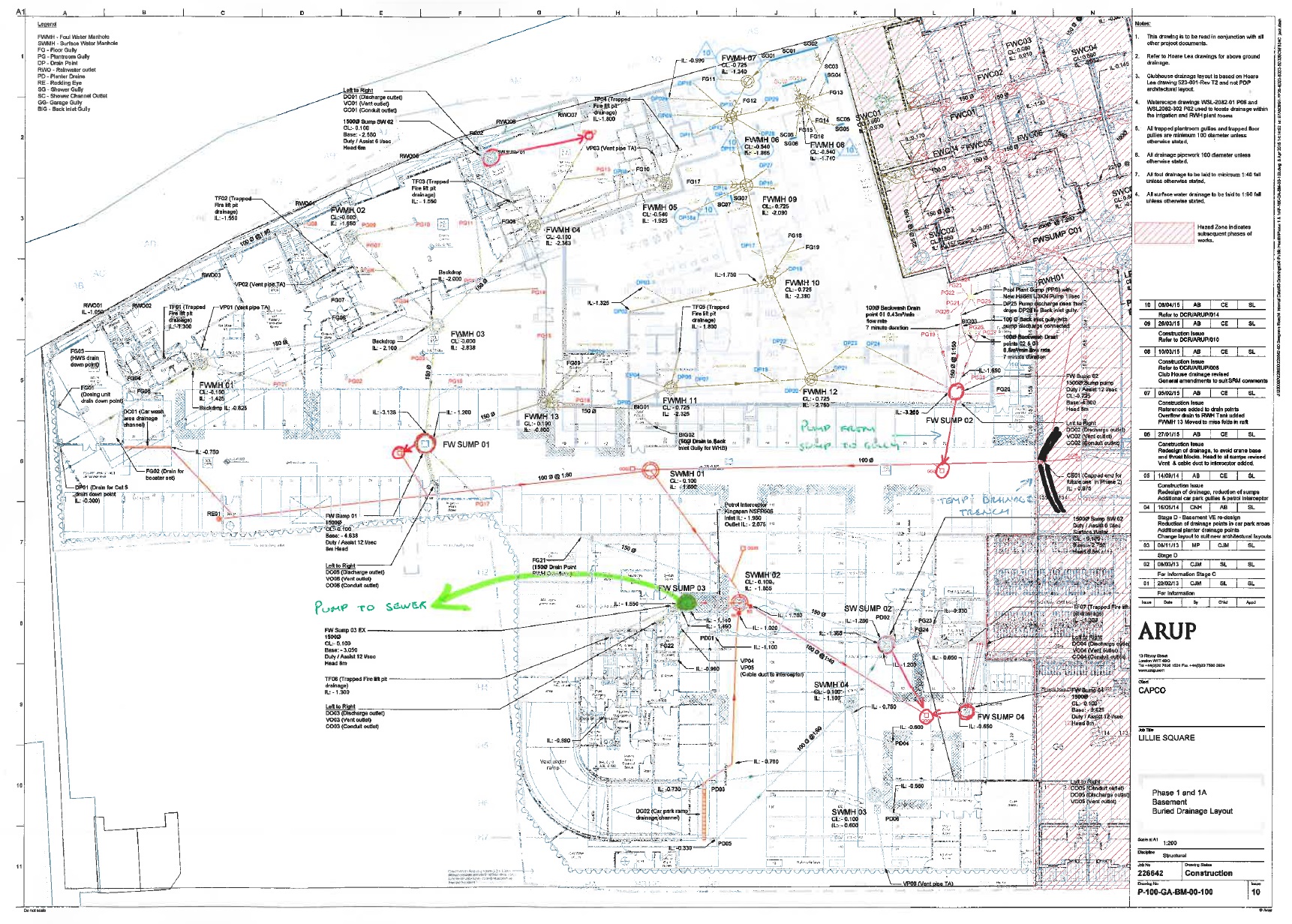
Despite me personally briefing this plan to the logistics sub-contractor and giving him a copy of the drawing he only had on site four 2″ pumps. It didn’t help that in my original plan I’d not considered two fairly important points:
- Podium slab penetrations. Incredibly I’d actually thought about this and still messed it up. I got out a drawing of the podium (ground floor) slab and ensured all the podium level service penetrations had been waterproofed. I even considered all the light wells and ensured that where up-stands in the basement were incomplete they were sandbagged to keep the water on the correct side. But I’d done it from a drawing. A drawing that didn’t show the massive holes in the slab that the tower crane pokes through! And stupidly I didn’t get off my ass, wander out onto site and have a look there. Thus the issue with the tower cranes!
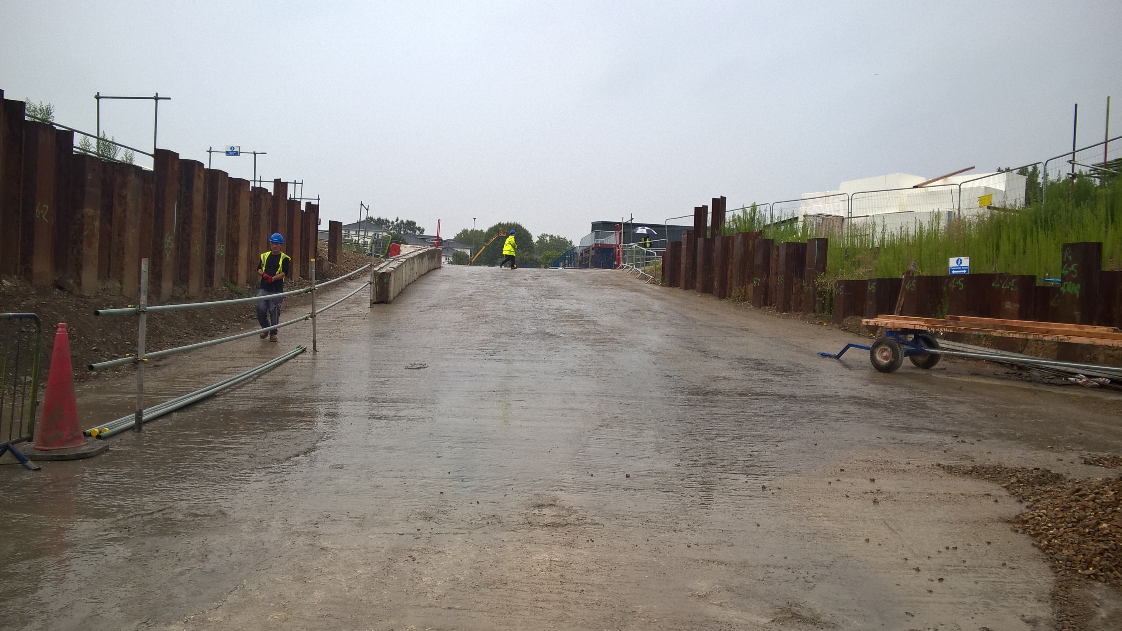
- The ramp. Logistically, and unusually for London, our site is a gift! We’re currently developing about 20% of the old Earls Court exhibition centre car park. Leaving the other 80% for logistical space and offices and the like. We’ve then got a large ramp that leads from the log area to the basement level. What I’d failed to consider is that every drop of rain that landed on that car park made it’s way down the ramp. It was like Niagara Falls (see Brad’s blog for images)! We were simply unprepared for that amount of water flowing onto the slab in that location.
The Monday after “The Wettest day” the construction manager sent out an email detailing what addition measures were to be taken and by who. My job was to ensure the podium drainage penetrations were connected to the basement drainage system with the topside waterproofing removed and that the tower crane penetrations had sandbag bunds around them. I completed my jobs that week. Our services manager was tasked to put a trench across the bottom if the ramp to divert the water somewhere other than straight into the basement. He didn’t bother. I had noticed this by kept my nose out of fear of upsetting anyone. I get enough grief from my project manager as it is – he is very angry and for some reason hates me!
Fast forward to yesterday and on my way to work I read the news on my phone. I saw the headline “month of rain expected in 48 hours”. “Wow, that us not good news!” (Or words to that effect) I said aloud, much to the surprise of the old lady next to me on the tube.
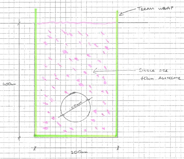
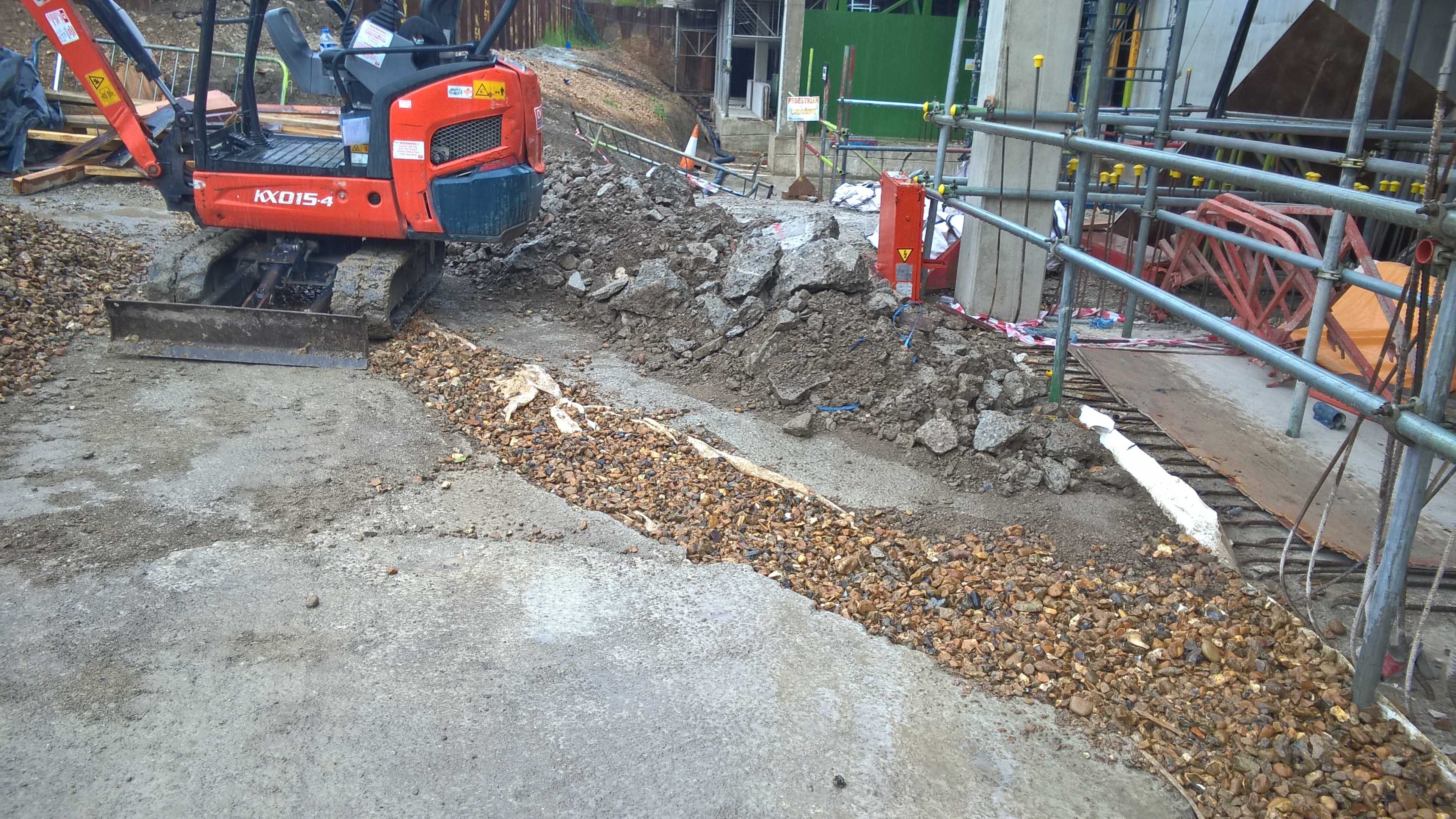
When I got to work I stopped worrying about offending anyone and just set about making it happen. I got a trench cut across the bottom of the ramp. I ordered some teram and 20/40 (aggregate sized between 20 and 40 mm – apparently getting single sized aggregate is pretty difficult these days!) to be delivered the same day. I got a plastic duct left over from installing the tower crane cables and had some holes drilled in the sides. I put the teram in the trench, stuck in the duct, back filled with the shingle and linked the end of the duct into the surface water drainage system that links phase 1 (our bit) to phase 2 (the bit the other side of where the ramp is).
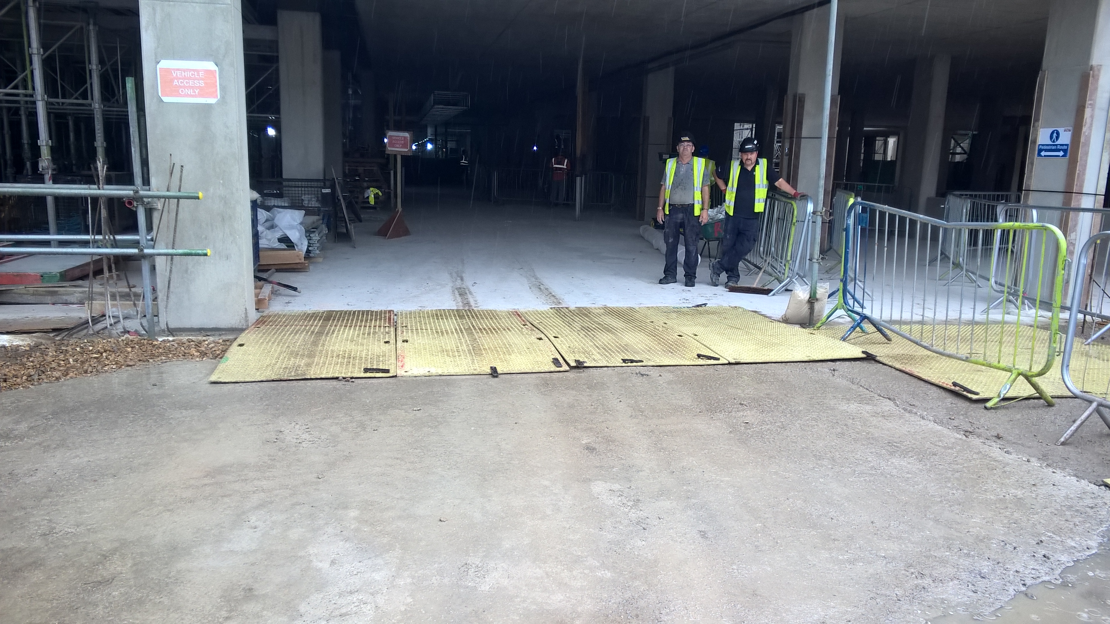
So come the day of the biblical downpour and it hasn’t come. Sure it rained a bit about lunch time but nothing requiring us to put two of every trade onto a large boat (bar the QS’s who gave me loads of abuse for spending more money doing this than it would’ve cost to actually build an arc). But the system is working, the basement is dry and definitely has much more capacity than is currently being used. So I’m taking solace in the fact that it worked. It may not be pretty, it may not be high tech engineering, it may not have required a Microsoft Project printout on A1 paper, but it worked.
Lessons:
- Don’t do anything just off a drawing, get off your ass and have a look – my bad.
- You’ll still probably miss something anyway, so just deal with it the best you can when it happens.
- French drains work.
- Never trust the Met Office.
7 click central
Things aren’t looking so rosy in our principal M&E sub-contractors’ office. Their office consists of about 40 personnel and they’ve been on site since January, however, to date they’ve had 12 people leave the project (granted one was a death – natural causes) and a further 4 are ringing for a taxi. As I understand it this is incredibly high turn over and made even worse by the fact that SRW is a company that prides its self on normally having low turn over.
What’s the issue?
Its very simple – toxic leadership. SRW’s package is split into two halves – fit out (putting all the MEP kit in the apartments) and infrastructure (getting services from where they enter the building to the apartments). Each half is headed up by a director and both directors have a leadership style which leads a lot to be desired. This is resulting in the out flow of people. What is particularly worrying is that the flow doesn’t seem to be slowing down, if anything as the job is getting bigger and more pressure is being put on the flow is increasing.
What’s the impact?
The project is loosing some quality personnel, but even when an individual who isn’t particularly talented leaves there is still a loss of knowledge. The problem is further compounded by the state of the construction industry in London; between Battersea and Vauxhall alone there are over 5 major construction projects (that’s counting Battersea Power Station and it’s 3 current phases as 1). In short there are lots of jobs out there and a huge skill shortage to fill them. People who would have been section engineers are stepping up to fill package roles and package managers are becoming project managers. SRW are now struggling to recruit into the gaps they have in their organisation. A recent SRW vacancy at Battersea attracted 11 applications, but hasn’t resulted in anyone being placed. I’m not sure whether this is because there wasn’t anyone of a high enough calibre applying or whether the applicants got wind of the situation on site and decided to look elsewhere. SRW now have a significant number of gaps, which means that the work load of those that have stayed is increasing rapidly. This is causing problems in the way the works are being managed, increasing stress levels and will ultimately lead to more people leaving.
I’ve felt this first hand in the last week when I was engaging with SRWs commissioning manager about flushing a riser in order to bring on line temporary heating. It felt like the blind leading the blind – I’ve never commissioned anything in my life, but I felt like I had a better grasp of what was required than SRWs manager. Whether this is because he’s stretched in other areas or because he lacks experience I don’t know. Every question I put to him went straight to the trade contractor with no value added. I’ve also had to review the RAMS for this process this week, which was a painful experience. Again the paperwork has come from the trade contractor. SRW have signed it off as status A, which means it is absolutely faultless in their eyes. This is utter rubbish, it’s status C at best, which means it needs re-writing.
Every cloud has a silver lining
We were supposed to be starting flushing on Wed next week. I’m currently struggling to get drainage sorted for this activity, which means I was staring straight down the barrel of a delay notice. Fortunately for me SRW have only just (yesterday) submitted their RAMS. So I can contractually take 10 days to review the paperwork before telling them its crap and getting them to resubmit; SRWs half hearted effort checking their trade contractors paper work has saved my bacon (presuming I get the drainage sorted).
Once I’ve got TMR 2 out of the way I’ll hopefully provide an update on where we are with the flushing – I’m sure you can’t wait!
Oz PCH – Chilled Water (CHW) Pipework Flushing.
Introduction
Usually once all CHW pipework has been installed in all plantrooms and throughout the whole network this is when the commissioning process of flushing and cleaning commences. However, on this project Central Communications Room 2 (CCR2), which houses all the communication equipment and creates a large heating load, was required to be switched on early. Therefore the heat load required to be controlled and cooled so the decision was made to use the intended CHW system to do this; however, there were a number of plantrooms still under construction with incomplete pipework. The work around was to shut off the isolation valves from the lower basement to the rest of the building and using the intended CHW main pump room (plantroom 10) flush and clean that part of the pipe network. This meant that we could then open up the isolation valves from the Central Energy Plant (CEP), which provides CHW to the entire Queen Elizabeth II Medical Centre (QE II MC) site, and provide the CHW required for CCR2.
So What?
In doing this and maintaining the CHW from the CEP through plantroom 10 to cool CCR2 it meant that when the remaining plantrooms and CHW pipework was finally installed that part of the network would have to be flushed and cleaned separately to avoid contaminating the lower basement pipework that has already been cleaned and is operational but more importantly avoid contaminating the CHW system from the CEP which also feeds the rest of the QE II MC site.
The Solution
It wasn’t possible to shut down CCR2 and so the only solution was to flush and clean the remainder of the network in bit-part fashion – not ideal or the way it should be done. Why? Because it meant that we could no longer use plantroom 10 main pumps and instead had to get the subcontractor (Fredon) to use a stand-alone flushing rig (with its own pump set). The intention would be to flush and clean each plantroom separately back to the point of the lower basement isolation valves.
The Issue
The first plantroom to be flushed (plantroom 7) was set-up with the flushing rig and ready to go when disaster struck. The armoured flexible coupling from the rig to the pipework had an epic fail and flooded the plantroom. Fredon informed us that the flexible hose burst off the flanged collar under the pressure (3 bar) and volume of water. BSIRA guidelines state:
The specified minimum flushing velocity should be that indicated in the table (figure 1), or the design velocity plus 10%, whichever is the greater. The flushing velocity must be selected based on the largest pipe size in the system or circuit to be flushed.
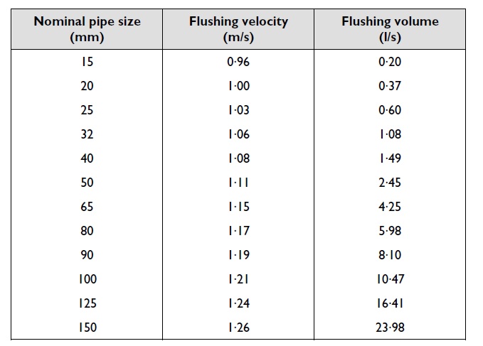
Figure 1. Minimum water velocities required to move 5 mm diameter steel particles in horizontal medium grade steel pipework (BSRIA).
So for a pipe diameter of 150 mm the flushing velocity should be 1.26 m/s with a flow rate of 24 l/s to flush out a particle size of 5 mm in diameter. The test rig was actually set at 27 l/s which equates to 1.42 m/s (at 150 mm pipe) which is over the velocity in the figure 1 table. Figure 2 shows the flushing rig and figure 2 the rig’s flanged connection end and butterfly isolation valve.
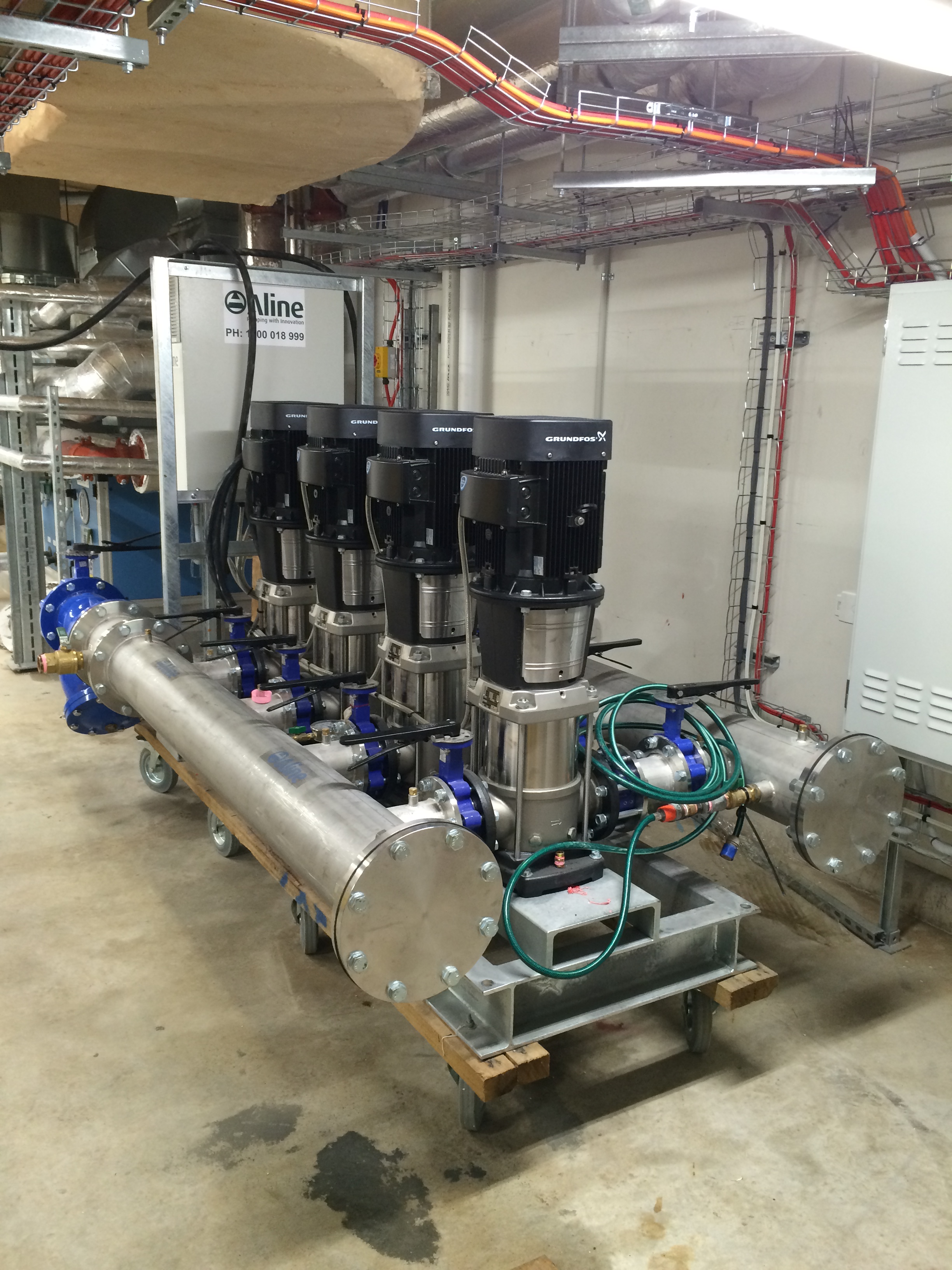
Figure 2. Fredon’s Flushing Rig.
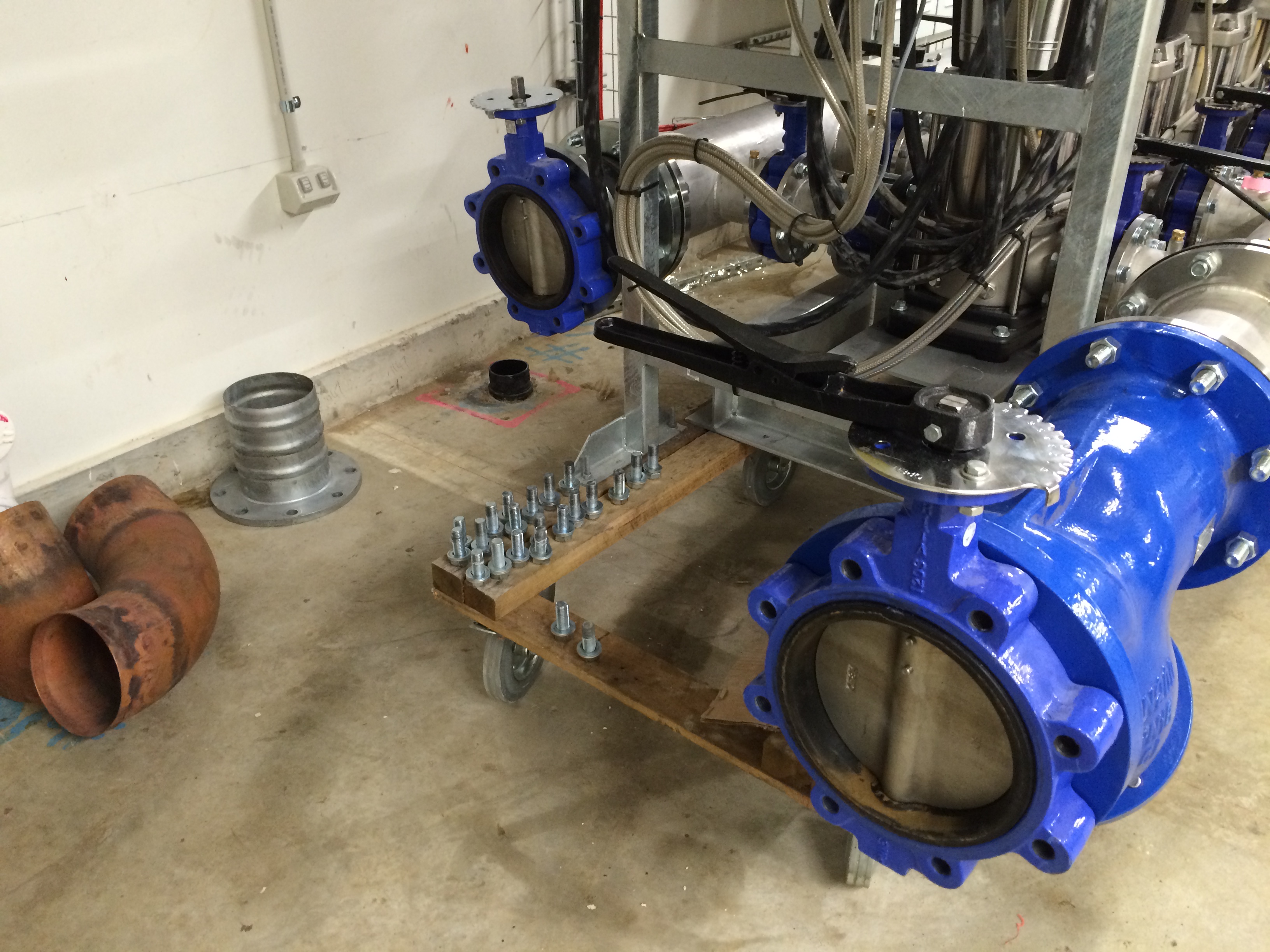
Figure 3. Flushing Rig Flanged Isolation Valve.
Fredon say that the two securing bands (like a large jubilee clip) must not have been tight enough as supplied by the hose manufacturer and under the weight and pressure of the water bust it off the collar. You can see the collar in figure 3 (circled red) but the hose had already been removed from site to be tested where it can’t do any more damage. Fredon gave it another go, after tightening the bands, but it popped off again. Their solution was to use a ‘hard’ coupling using 200 mm diameter copper pipe (figure 4). This removes the flexibility and ease of connection to the rig and means that until the flexi hose is proved fit for purpose every plantroom will most likely need a separate set of copper coupling dependant on the network connection outlet heights and accessibility – hence the preferred flexi hose method. Figure 5 shows the network connection flow and return points reducing from 200 mm rig pipe diameter to 150 mm system pipe diameter.
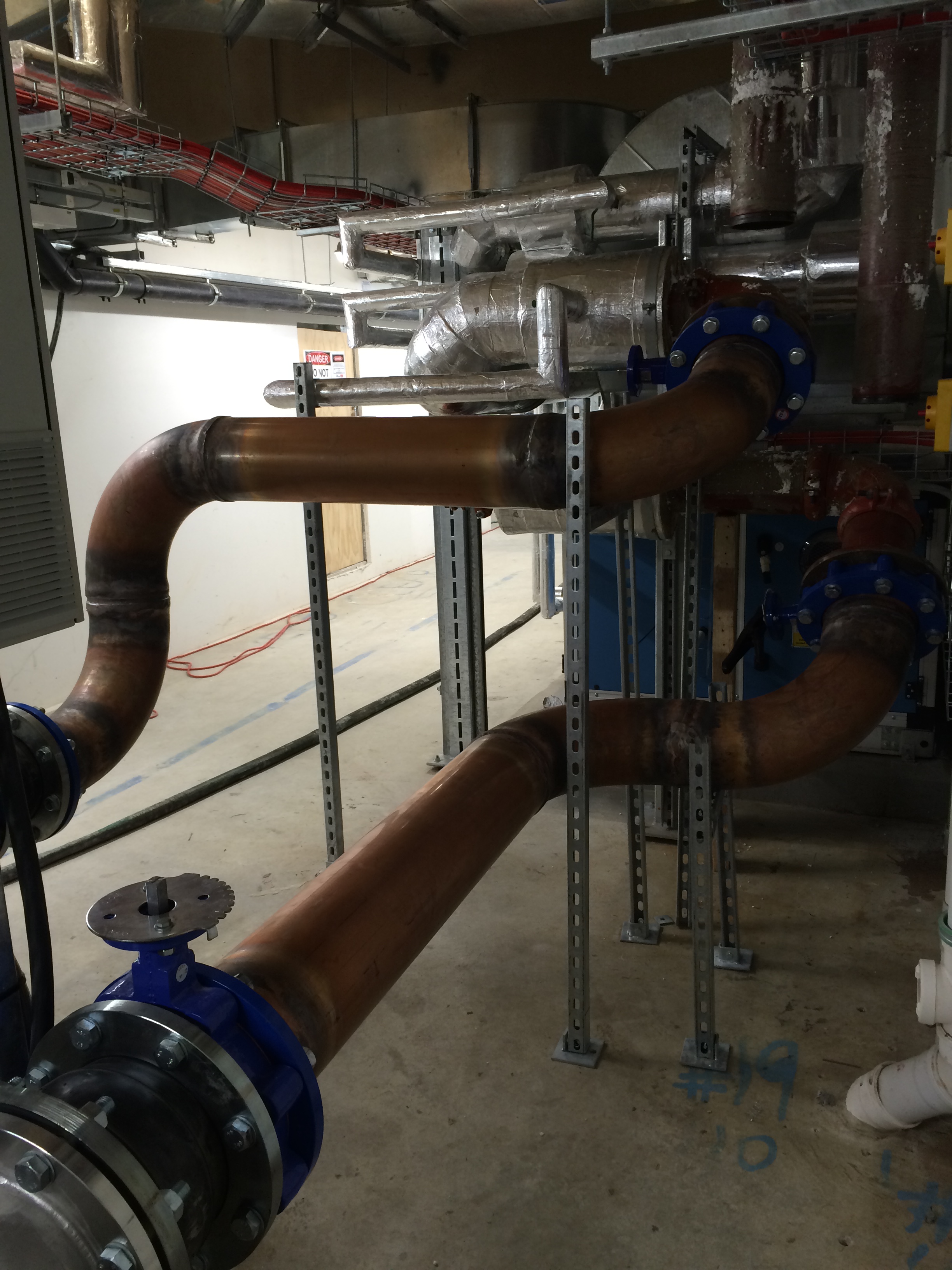
Figure 4. Rig Hard Copper Coupling.
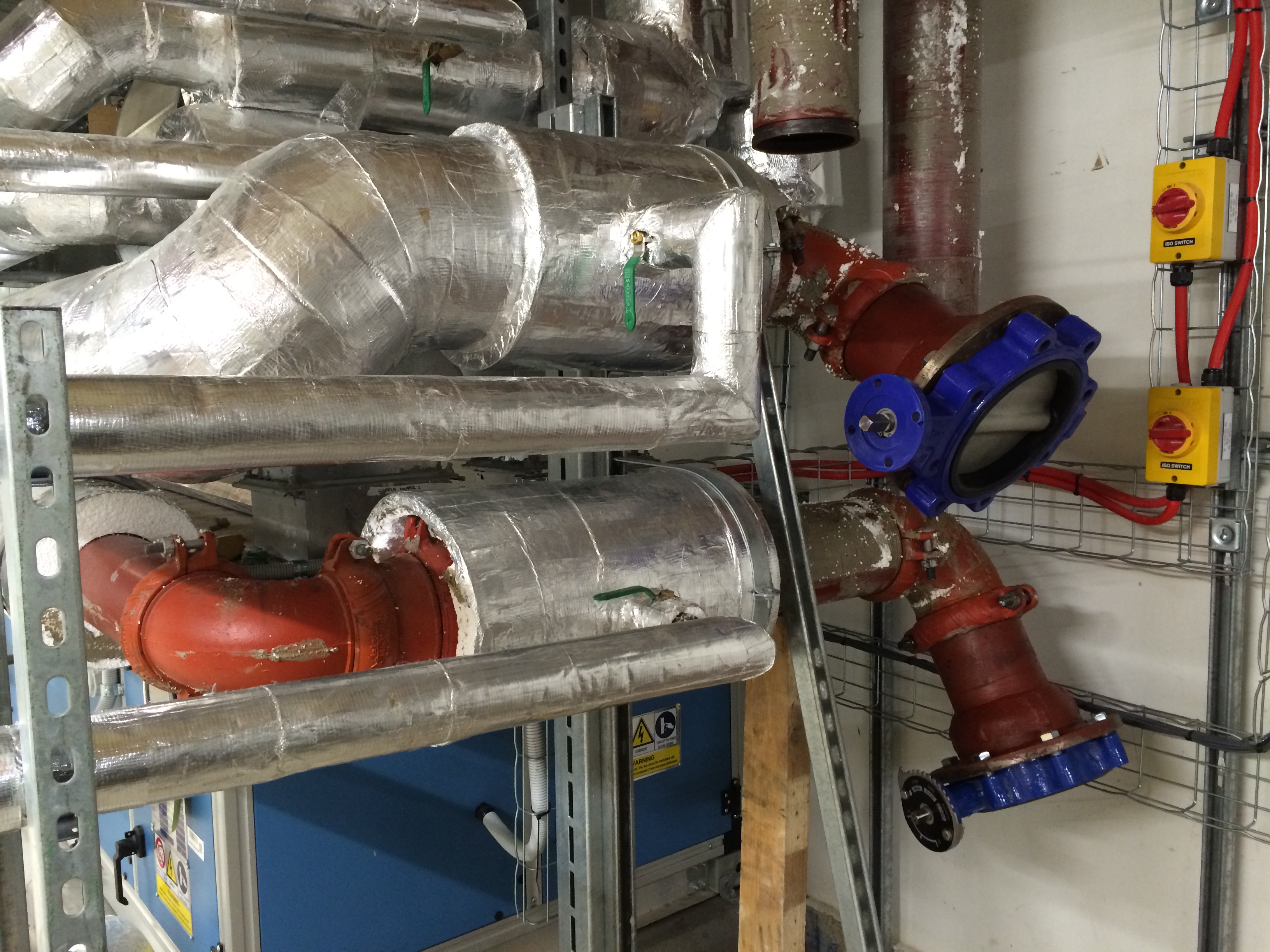
Figure 5. Plantroom Network Connection Points.
The Damage
Figure 6 – 8 shows the damage caused from the flooding. It doesn’t look like much but water being water will find its way into every gap possible. To add insult to injury the plantrooom floor hadn’t yet been sealed water tight so water ran between the gaps where, ironically, the drainage pipework stacks are fitted into the concrete slab and came through to the ceiling of the level below damaging some ceiling tiles and insulation.
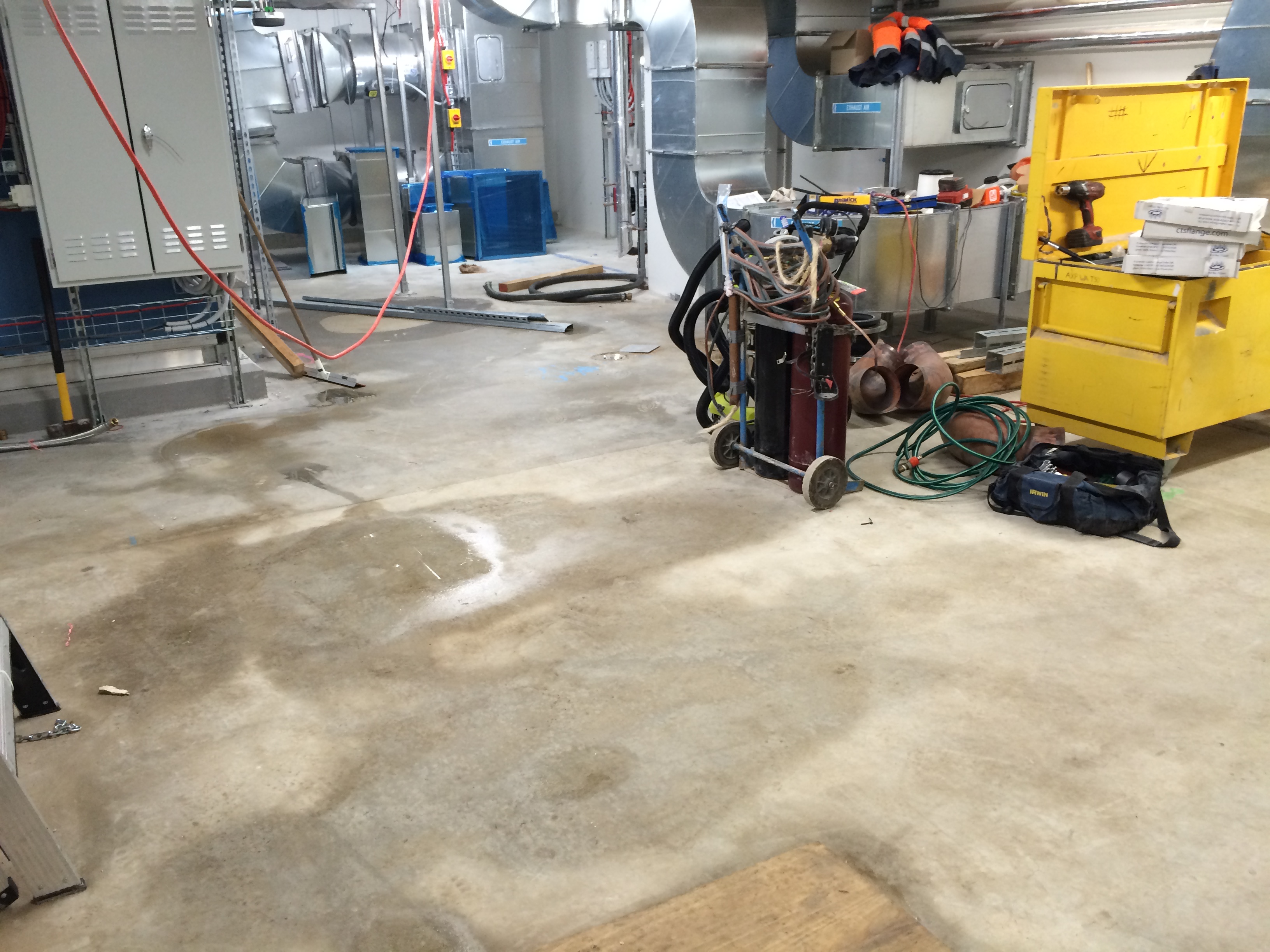
Figure 6. Plantroom 7 Water Damage.

Figure 7. Drainage Stacks.
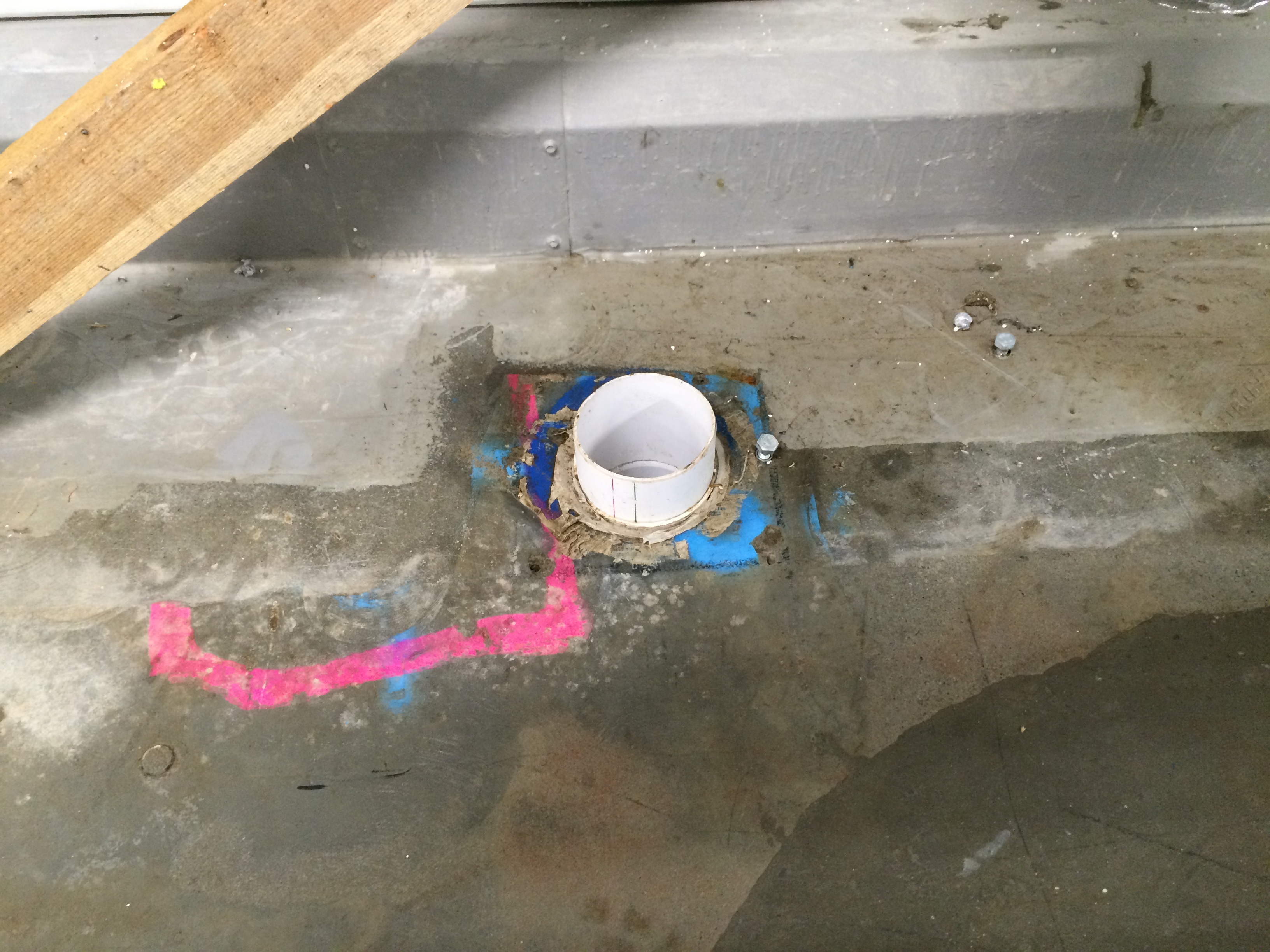
Figure 8. Tundish Drainage from AHU.
Additional Potential Issues
There are also potential issues of someone accidently opening an isolation valve between a plantroom and a riser feeding into the lower basement circuit and therefore, if not flushed will contaminate the CEP.
A second order affect is the Floor Control Rooms (FCRs) which house some IT infrastructure. They aren’t operating at full capacity yet so only a small percentage of the heating load is being seen. Due to this small load these areas still need to be kept cool and so the FCRs on the floors that have CHW supplied are flowing through Fan Coil Units (FCUs). The issue is that because the BMS is not yet fully operational the motorised control valve fitted to each FCU cannot be adjusted. And even with the double regulating valve of each leg manually turned down to the minimum setting the CHW in the FCU is around 6 ºC. So What? This is causing condensation issues where the temperature in the FCR is getting close to the Apparatus Dew Point (ADP) of around 14 – 15 ºC and compounded by the high humidity as the external façade hasn’t been installed in that area yet. This will only get worse when the outside temperature begins to rise and cause an even greater ∆T between the FCR and outside. The condensation could build to the point where it forms bigger water droplets and drips onto the IT eqpt thus potentially damaging it. Therefore this requires swift resolution; most likely in the form of either getting the BMS up and running or introducing temporary heating.
Conclusion
At the heart of both of these issues was commissioning the CHW system in bit-part and not all off the main pumps in one go. However, it was deemed more important to get the CHW system partly operational to cool CCR2. I would have thought another way of providing cooling could have been done through temporary FCUs placed in CCR2. Another conclusion is that floors should be water sealed prior to any pressure testing or flushing in order to limit damage caused by potential leaks. This issue also highlighted that there should have been localised bunding put in place like there is in other plantrooms. Consequentially Fredon’s flexi hose failed its off-site pressure test and so they have continued to use the copper hard coupling throughout the remaining flushing of plantrooms across the project.
A small commercial conundrum
In my quest to get works in thermal plant rooms underway I’m still chasing down builderswork interconnections that have been missed. In order to get the works underway a simple instruction is requied, which is easy to get from the blockwork-package QS. It’s him that who makes the decision as to who will cover the costs for the remedial work, but I had to provide the background information as to what has happened. In this instance the requirement was for 3 no holes to be formed in a blockwork wall which were missed at the time of construction due to the blockwork contractor (Swift) not having the information at the time of construction. The issue is complicated slightly by the fact that the BWIC details have subsequently been revised. The timeline of events is as follows:
03 March 15 – SRW issues BWIC information to CCL, drawing revision is C01.
02 June 15 – Swift start constructing blockwork in thermal plant room 12.
05 June 15 – CCL issue CO1 revision BWIC information to Swift (our informaiotn management isn’t exactly great, but that could be a completely seperate blog).
09 June 15 –Swift complete blockwork in this area, BWIC formed on one wall, but 3 missing on another wall.
02 Jul 15 – SRW issue CO2 version of BWIC information to CCL. Hole location does not change, but size does (increases).
05 Jul 15 –CCL issue CO2 BWIC information to Swift
I ran this by an MEP QS prior to submitting it who was unable to shed any light on who would pay. I’ve had the instruction issued and the work has been carried out, but I’ve not had the opportunity yet to discuss the matter with the blockwork QS for my education. In my mind the CO2 revision would have caused Swift to have to carry out the work anyway and the differenct between knocking out 2 blocks and blocks is minimal so SRW should bear the cost (which will be trivial). Thoughts?
Site Two Fifty One – Problems, drainage and digging
Site Two Fifty One – Problems, drainage and digging
After the jubilation of completing the piling last week, and the removal of the rig on Friday night, a nightmare awoke the site today.
One of the tower crane bearing piles was piled in the wrong place. Coordinates were used to set it out and a typo of a 2 rather than a 3 mean the pile is 10m out.
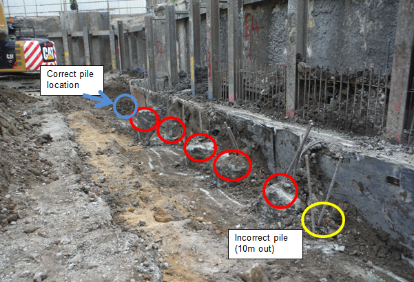
Why – it was a simple typo but where was the gross error check to double check it was in the right place?
The dywidag bars that project out of the ground were / should have been a bit of a giveaway. The person who set it out was a junior trainee student on attachment under the umbrella of the Site Engineer and myself.
So what?
The piling rig has left and the tower crane foundations, grillage and design all need cat 3 checks (due to proximity to Network Rail) which have taken weeks to organise. The problem of what to do now also needs to be resolved.
Options.
I can’t proffer the solution other than to say options include:
- Redesign of the tower crane foundation using the piles that have been installed – unlikely to work as they were on the limits anyway. If something can be made to work and get around the eccentric loading this would be the least expensive option.
- Bring back the piling rig. This would be a phenomenal cost and time.
- Bring in a smaller piling rig to drill some piles to replicate a 750mm 24.5m deep pile. Costly but practical.
- Others. Announce the problem far and wide and hope the corporate engine of Laing O’Rourke can find a better answer.
Drainage
How do you go from a drainage layout plan to installing drainage runs?
Design, resource, construct. The design is done and construction seems to be within people’s competency. That leaves resourcing. The drainage supplier has not sent us a very good quote, leaving more questions than answers. Saint Gobain are the manufacturer of choice who have been helpful but that only goes so far.
Then other issues like where do the drainage points (vent pipes, gullies, drain points, etc) actually sit arise. Ask the designer (Waterman) and they refer you to the architect. So lengths, angles and connection pieces become unclear.
Gully points need a grate, p trap, extension piece, bend and connectors. No problem until the grate specified is and L15 strength which I think means able to carry a stress of 15kN/mm2 based of the picture below, fine for pedestrians but this is for a car park. That makes me wonder if the trap system underneath is sufficient.

Aco Drainage Load Class Table http://www.acobuildingdrainage.co.uk/about-us/load-class-table.aspx
It is likely I am over complicating things but this does not seem to be as straightforward as it should be.
Digging
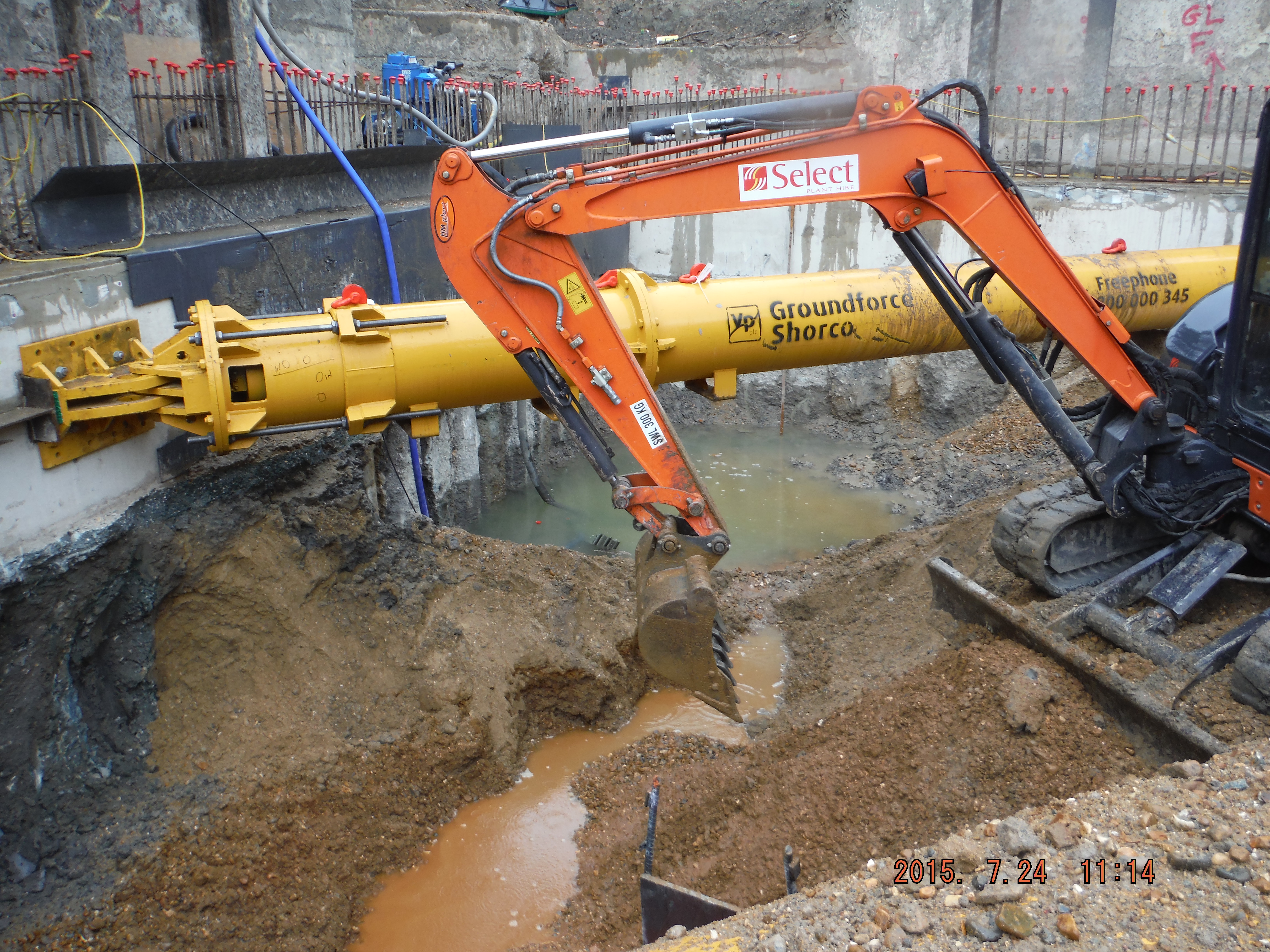
The site excavation continues with the London Clay now appearing at about -4.5m AOD. A bit higher than expected… repercussions include greater skin friction perhaps, less value to be gained from excavated material. The dewatering has not been too much of an issue using the approach of dig, dewater, dig, dewater.
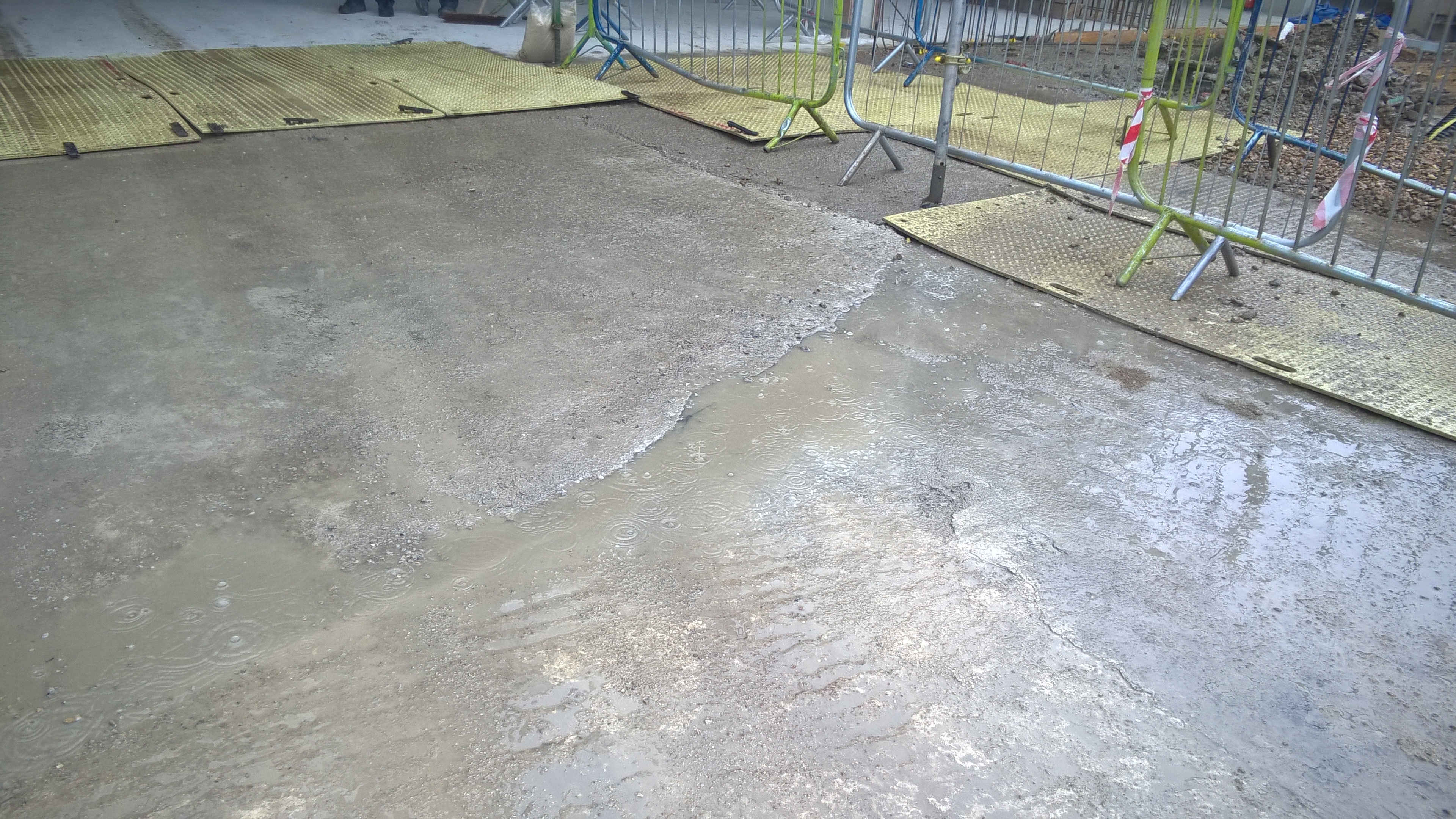
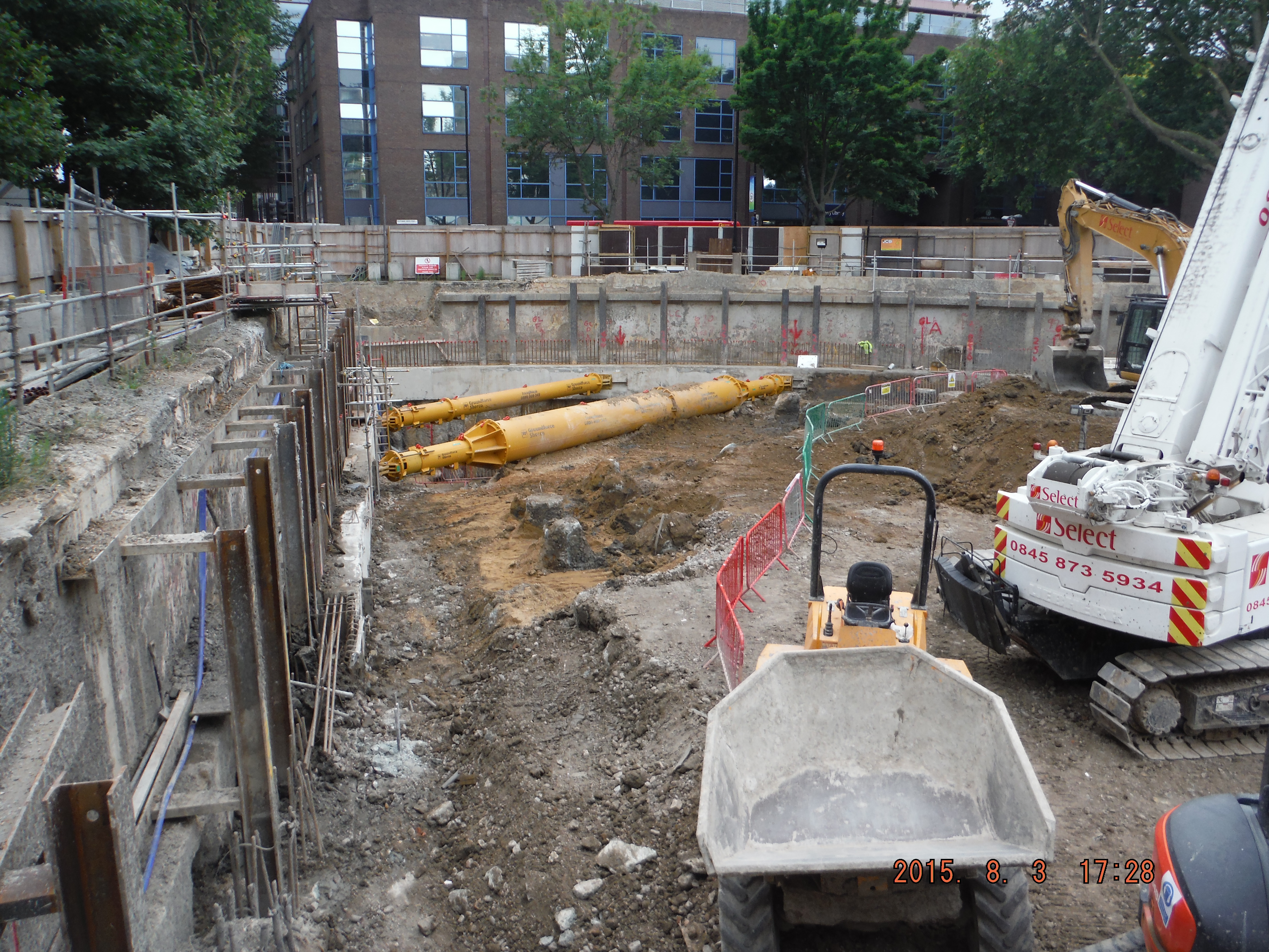
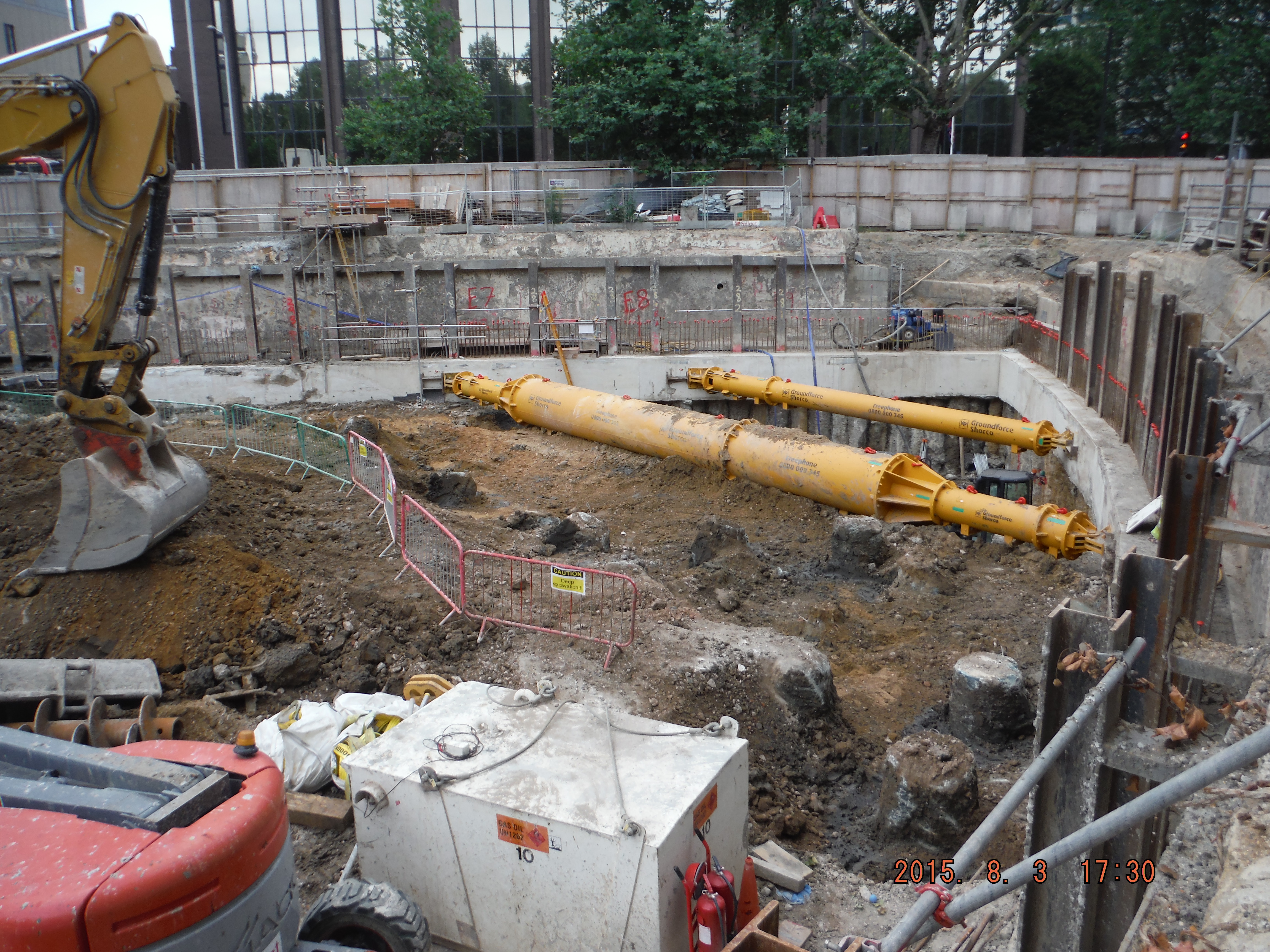
However revealing “interlocking” secant piles is starting to show that perhaps they were not as locked as hoped. Either that or the very damp patch is being caused by something else. A few photos of the progress of installing the props.
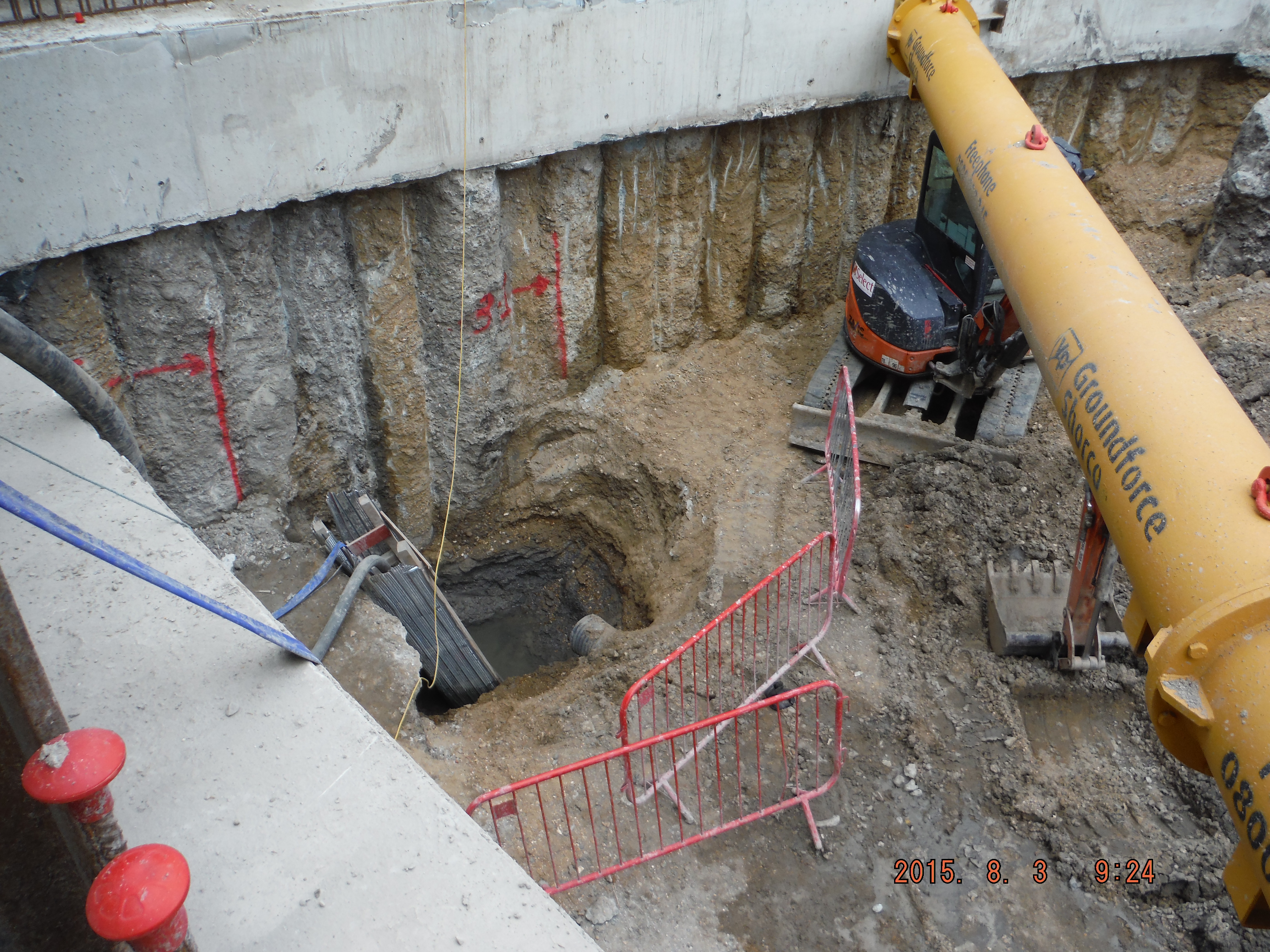
Note bearing piles have to be broken down in order to install the props. The excavation then continues to depth and then the protruding piles are snapped because the reinforcement cages have been plunged to cut off level.
Ground water (and plenty of rain) pooling in the corner ready to be dewatered.
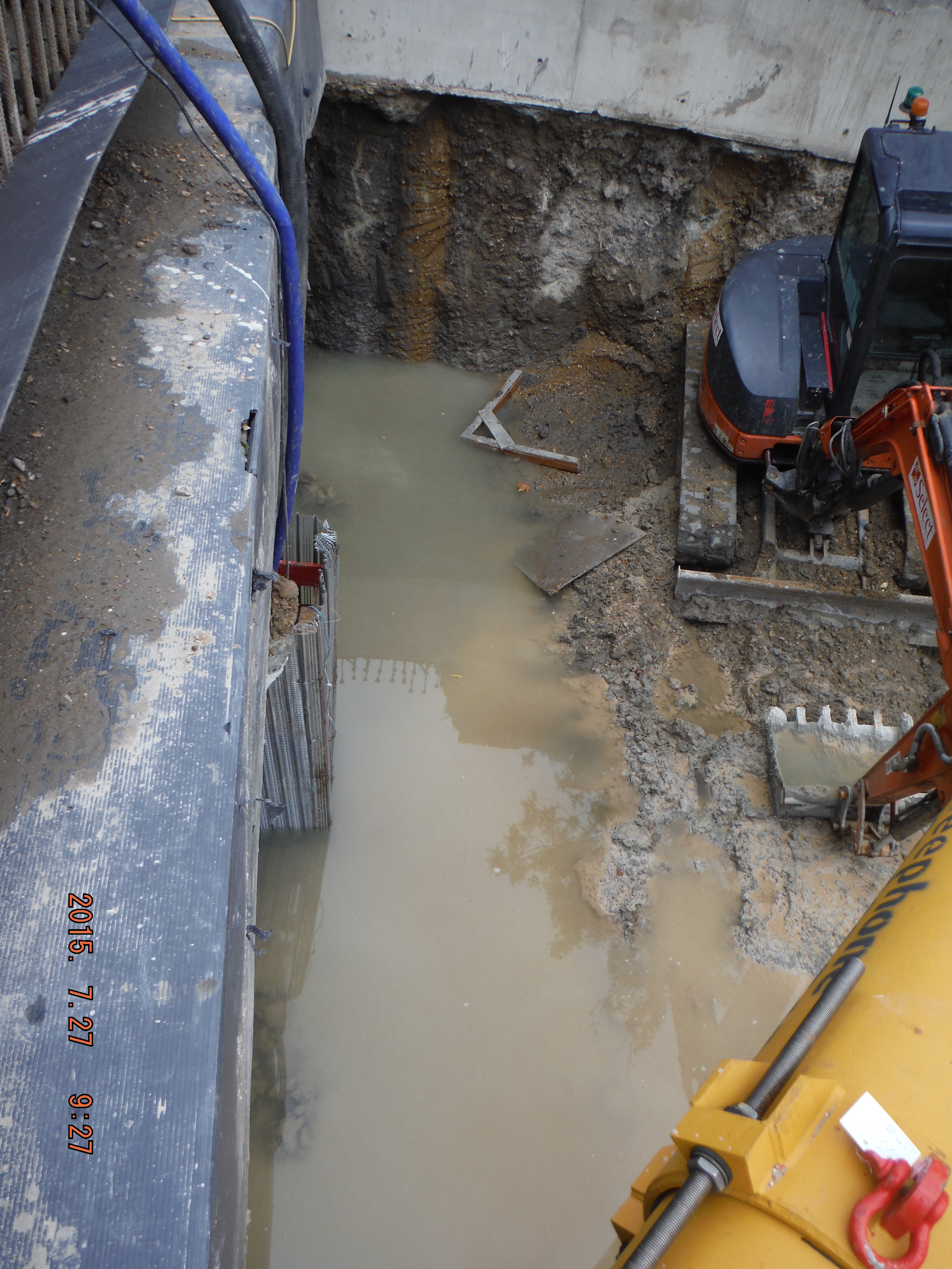
2 inch electric pump and 3 inch diesel pump used to remove water.
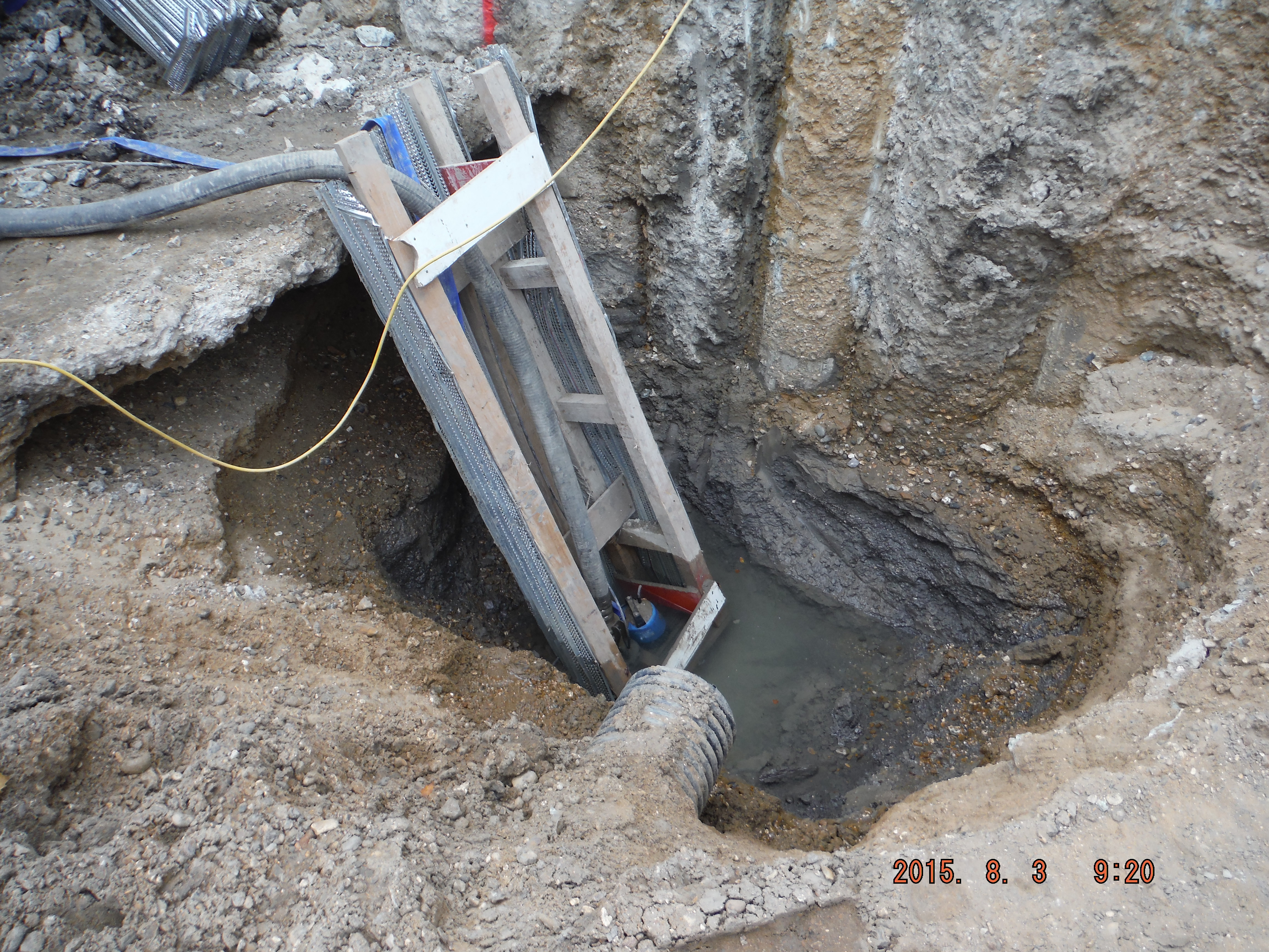
Pumps submerged within sump at bottom of excavation (close-up)
Pumps submerged within sump at bottom of excavation
Mass excavation (reduced dig) in order to install next prop.
Mass excavation (reduced dig) in order to install next prop.
