Archive
Oz PCH – Bean Counters Hard at Work.
A few weeks ago whilst setting up for my weekly commissioning mtg I noticed that the projector wasn’t working. This is one of only two projectors JHG have in K Block (project office) and they pretty much get hammered all week; so no surprises that one would give up the ghost at some point.
However, two things struck me as a surprise, firstly was that the projector had clearly not been working prior to my mtg and so had broken on ‘someone else’s’ watch; the assumption being, that particular ‘someone else’ had reported it in order to get it fixed/replaced – sadly not the case. This is a clear example of bad admin/slopping the shoulder, so when I asked one of the services co-ordinators to report it, it was the first HR at heard of it.
The second surprise was much more shocking. After HR had put a request in to the IT dept, which were apparently absolutely useless, all they could come back with was ‘we cannot provide you with a spare and suggest you might be able to borrow one from Head Office but they have no spare either’. So how about purchasing a new one? Accounts won’t approve purchasing another one this late into the project – really, really!
A quick google search for a similar standard model of projector found this for $800 approx. £400:

And there are cheaper ones at around $600.
I could think of lots of examples where this project is wasting that sort of money and it’s not even like it has to be purely associated to the project as it can be reused for subsequent projects to come.
So What?
Does this mean Friday beers and pizza will be stopping????
We will just have to make-do with the one we have, although it has already caused issues and what happens when that one decides to break?
I may approach our services director and see if he can purchase one independantly thus circumventing the IT dept.
In Other News
It’s the Aussie Footie League (AFL) grand final this weekend with the local Perth team, the West Coast Eagles, well up for it – Come on the Eagles!

Words not required!
Damo has been texting me, so words are required…
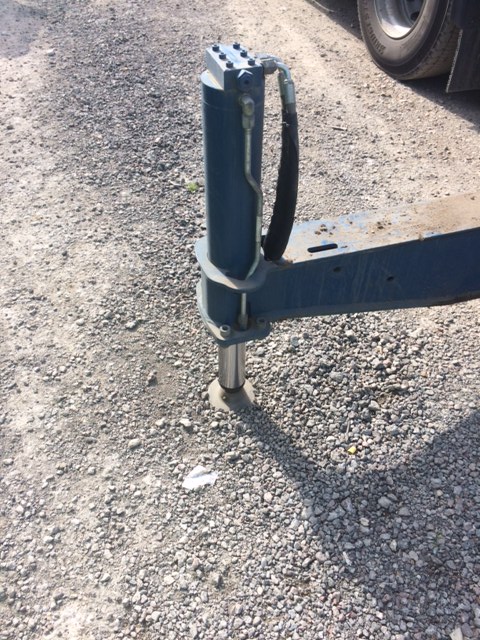
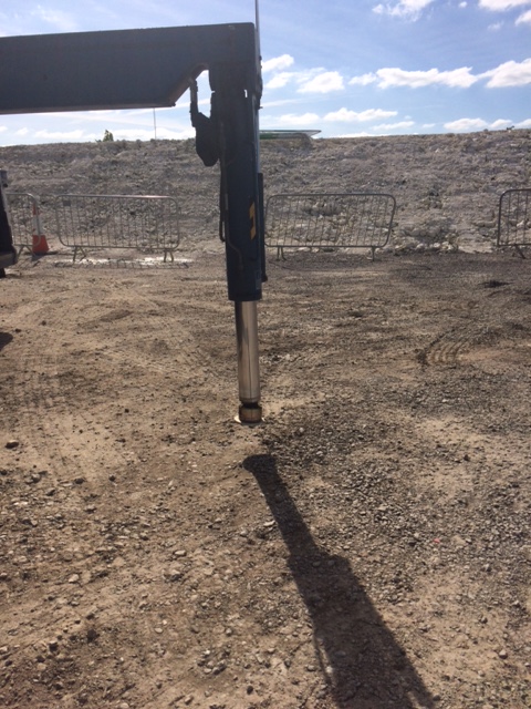
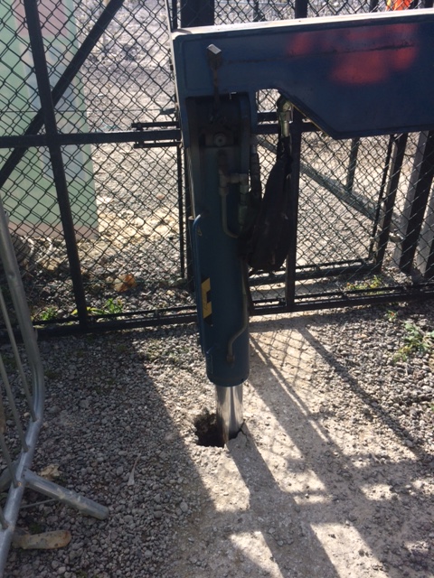
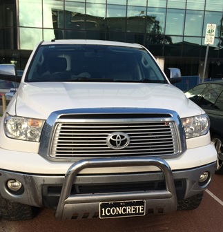
These are outriggers on the side of a lorry. I walked out of the office to find the truck like this, the driver said he hadn’t noticed but thought the ground was fine.
Before you ask, the pads were neatly stored behind the cab where the driver keeps them safe, warm and clean!
And as i’ve just replied to Damo, no calcs were required to work out the ground wouldn’t hold, a simple heel test would have told anyone that (not to mention the car park rutting about 6ft away which I should have taken a pic of, doh)!
The Good
The Bad
The Down Right Ugly!!!!
A Quarry Conundrum..
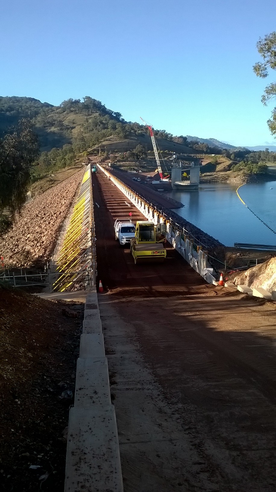
1. Project Update. In order to raise the Earth and Rock-filled Embankment dam here at Chaffey Reservoir, a reinforced earth wall (RE Wall) is currently being installed along the existing crest of the original dam (broadly speaking). As the engineer responsible for raising the dam crest, the RE Wall installation falls firmly within my remit. The works have been subcontracted to Fusion Civil Pty, an established earthworks company specialising in such structures. However, aside from the considerable size (500m x 7.5m x7.22m), it is the fact that the earth core is composed of three very differently graded aggregates, vertically aligned into three specific zones that makes this particular RE Wall quite unusual. Such a design has been adopted in order to control the rate of seepage whist preventing any water being visible on the downstream face. The zoned fill technique has also been adopted within the existing embankment dam below, however this also has rock armour installed on both the upstream and downstream external gradients. The primary impact of having zoned fill material within the RE Wall is the slower rate of construction; a fact that Fusion Civil are currently discovering to their cost (quite literally).
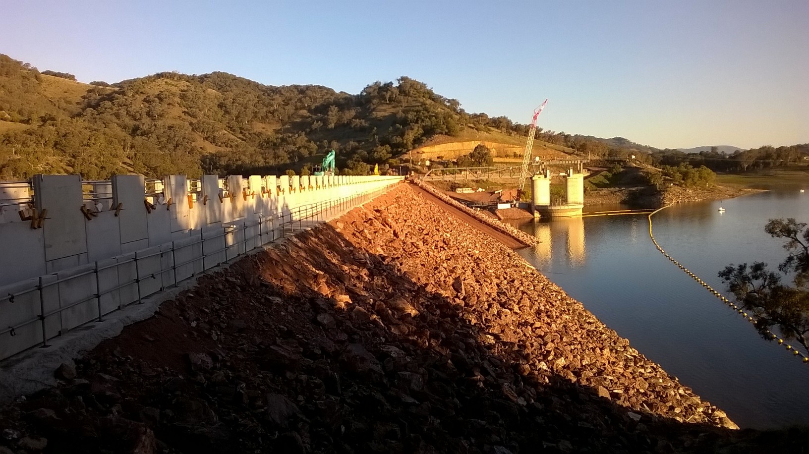
Chaffey Dam & RE Wall Upstream Face
2. Quarry. As well as being the engineer responsible for raising Chaffey Dam I also manage the on-site quarry which includes the sourcing, screening and crushing, load/ haul and all associated QA. A great benefit of the location here at Chaffey Reservoir is the local geology, perfectly lending itself to an on-site quarry for the both RE Wall Fill and road base material. Whilst it may sound to be a fulfilling and interesting role, the quarry has been the source of great frustration and angst since day one. Primarily, this is due the ‘cheggars’ subcontractor that John Holland selected to conduct all crushing and screening of the raw material. More to follow…
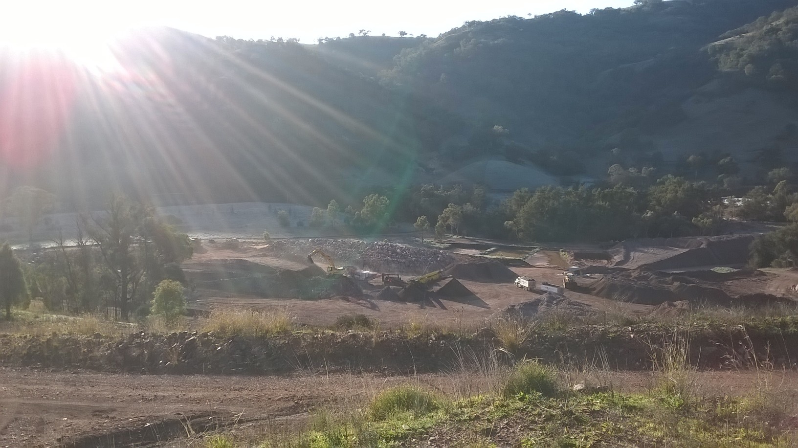
Chaffey Dam On-site Quarry
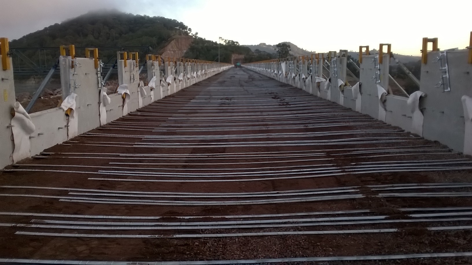
3. At present the RE Wall has had six 0.3m layers of fill and three staggered layers of 2m high precast concrete wall panels. Each 0.3m layer of fill material is hauled up to the crest from the quarry (≈1.1km), placed by a single CAT 730 articulated dump truck (due to with restrictions) before being spread and finally compacted by Fusion Civil. Once 50% of a layer has been placed and compacted I request that compaction is checked. A local Geotechnical firm provided the material technician who then determines the densities of the in-situ material using a nuclear densitometer. For QA purposes I chose to divide each layer of fill (≈ 950m3 aggregate) into two work lots (chainages 0-250m and 250 – 481m) based upon work lot sizing guidance within Australian standards (Roads & Maritime Services Q6). Finally the layer is strapped with the reinforcing galvanised steel straps as shown in Fig 2. Remarkably, it is the steel strapping that provides the structural integrity of the RE Wall. The straps provide the tensile strength that holds the precast concrete panels in position simply from the vertical load imposed by the compacted earth layers.
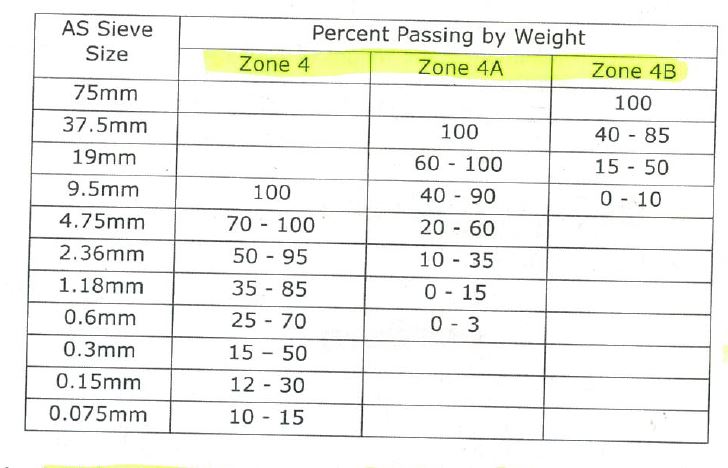
4. Volcanic Resources Pty are the subcontractor who are responsible for all crushing and screening of raw materials. Their primary function is to produce the correctly graded material as specified within the principle contract (CDASU GC21). The three materials are categorised as zone 4, 4a and 4b and increase in aggregate size respectively. Zone 4 material is the initial material located in the zone closest to the upstream internal face of the RE Wall in a 2m wide strip running the length of the wall. It has the lowest permeability of the three fill materials and is a reddish/ brown, well graded, angular, silty SAND. Zone 4a is the next material located in the centre 2m strip of the RE Wall. It is also reddish brown in colour and well graded but is a sandy GRAVEL that is designed to allow water through at a greater rate whilst providing structural integrity within the earth core. Finally, is the zone 4B material. It is placed in a 3.2m wide strip between the centre and downstream internal face of the RE Wall. It is a grey, poorly graded, angular, gravelly COBBLE that is designed to be highly permeable whilst providing structural integrity. Due to the high voids ratio water is able to pass freely and is a requirement as it is intended to prevent water ever reaching the very large rock armour on the downstream face of the Embankment dam. The idea being that if the public were ever to see signs of water penetration on the downstream face of the dam, panic would ensue.
5. Material Conformance. The latest issue has been one of material conformance. Until recently, Volcanic Resources produced all fill material simply using an industrial rock crusher and a mechanical screen. The machinery was set up to produce all three required products concurrently
( 4, 4a and 4B.) However, approximately five weeks ago the large zone 4B material was no longer required as I determined that the stockpiled volumes met the estimated demands for the remainder of the project. Despite this, the 4B material continued to be produced as an unwanted bi-product at a considerable rate. At this time, half way through the project, the subcontractor demanded that material prices were renegotiated due to the sudden reduction in his earnings. JH politely refused yet were unsurprised by the request due to previous grievances raised by the subcontractor. The subcontractor subsequently request that JH purchased a cone crusher, in addition to their own crushing machine. The idea was sold to JH under the guise that all the oversize waste material could then be re-processed, saving JH the need to excavate and haul further raw material. An agreement was reached whereby by JH agreed to hire a cone crusher up to a limit of $45 K (AUD) after which time Volcanic Resources would assume the financial hire costs of the machine.
So What?
7. Upon receiving the shiny cone crusher, material production rocketed and waste material stockpiles quickly diminished; a relief for me as the zone 4 stockpile was shrinking faster that it was being replenished. However, all was not well. Upon inspecting the material produced, it was apparent that there were distinct differences between the “pre” and “post” cone crusher zone 4 and 4A materials. The zone 4 material appeared overly coarse and failed to bind when moulded. Equally, the previously well graded zone 4A material was now very clean, uniformly graded gravel (perfect for a drive way NOT an RE Wall..). I immediately interrogated the Volcanic production staff on how they verified that they were producing conforming material (As the owner had already reassured me all was well). They simply said there were given a maximum aggregate size for each material and that was it…
8. 48 Hours later and the results confirmed the my concerns. Overly coarse zone 4 material and a uniform 4A material lacking sufficient fines to meet conformance. Fortunately the material had not entered the wall. Unfortunately, the material had contaminated existing stockpiles (but was fairly straight forward to identify and separate).
Lessons Learnt.
9. Do not trust a subcontractors’ word without checking, even if they are contractually obliged to make the product. Do not assume the obvious has been done; Common sense would say that as a material production specialist (i.e Volcanic Resources), if you change anything in a system you would re-test the new material to check for conformance. Clearly this was not done and they simply did not care. When I confronted the owner of Volcanic on the issue I was met with the following response:
“If you want your material to pass, why not test a stockpile that you know will pass?”….

Fill Material Production
10. Since this time, they have struggled to produce conforming material. The cone crusher failed to deliver what was promised and despite clear direction, they have attempted to load failing belt material directly in supply of the RE Wall. Much of my time is now spent in the quarry..
Solution.
11. I directed that we reverted to using predominantly raw feed (high % fines) with a blend of the oversize waste product. Whilst better, the material was still struggling to pass due to a lack of fines. As the ambient temperature has recently risen considerably, I directed that the raw feed stockpile was saturated in an attempt to bind the fines with the larger rock. This had an immediate positive impact and produced conforming material. However, the SPE was not overly happy as JH pay per tonnage and do not wish to pay for hauling water. My dilemma was, do I delay Fusion Civil in the production of the RE Wall due to lack of fill material or pay for the haulage of water?… The saga continues…
Reinforced Earth Wall – Left Abutment
Building Services and Bio-engineering.
Hopefully my absence from the blogosphere has not been too keenly felt however whilst away on Ex Bugaboo Tiger I have been continuing to learn. Sadly we weren’t able to stay at the comfortable hut in the Bugaboo Provincial Park but I stopped in for the a brew on the way past and I managed to have a look around the services. We also had a broken leg on the trip which required the combined talents of a doctor and engineer to bring about a recovery.
Building services.
The Conrad Kain Memorial Hut is remote. It is an hour’s drive up an unpaved surface to a car park and then a 3 hour steep walk from there. Apologies for the lack of detail however I restrained myself in my question asking of the Guardian:
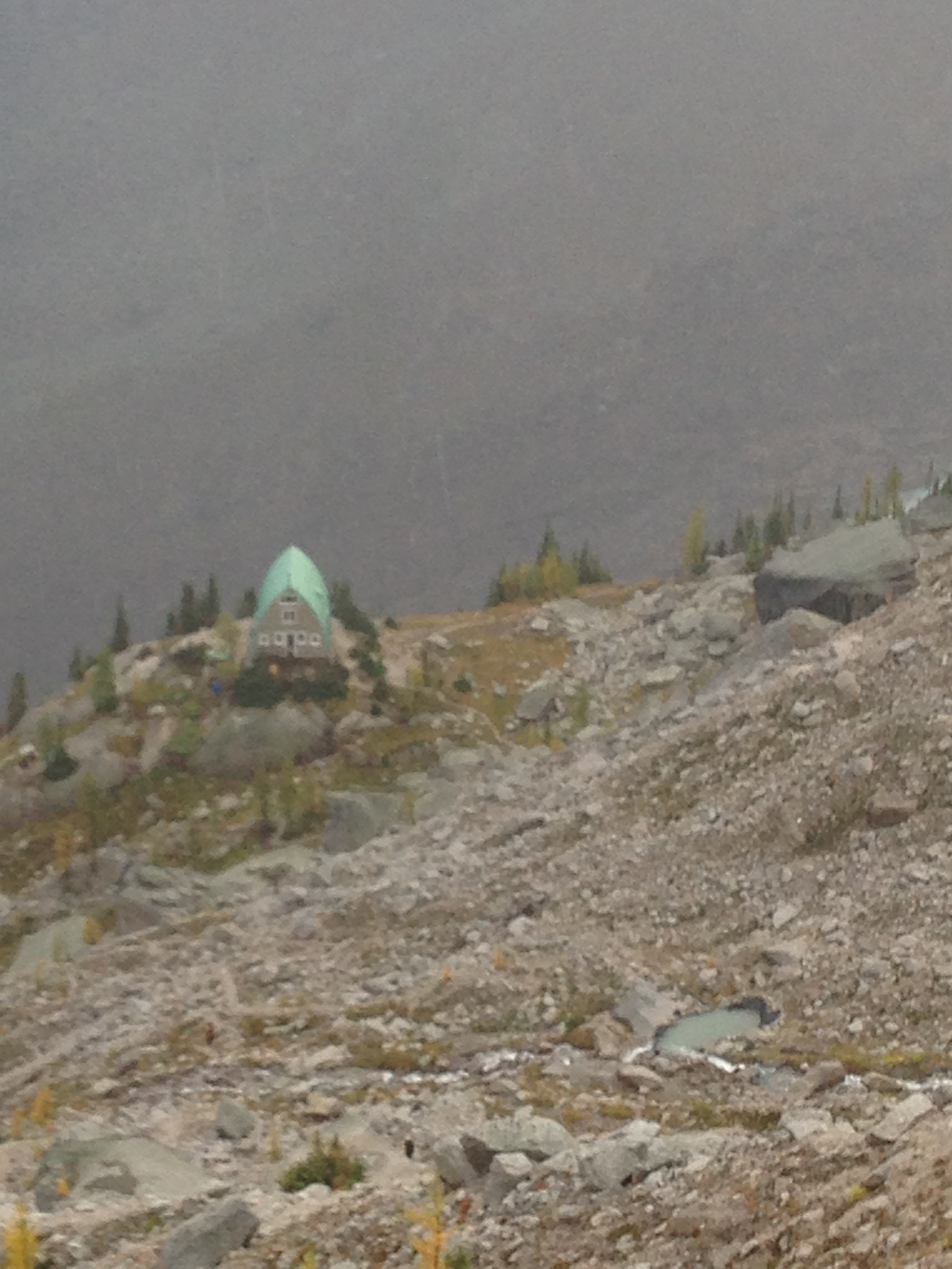
The remote Conrad Kain Hut
Water – It is just below a glacier, so water supply is not a problem. The water is filtered though being glacial the risk is low, the highest risk is from things like Weil’s disease as there is plenty of rodent life in the park.
Waste – The rules of the park are, if you ‘pack it in, pack it out’. This is well advertised and people we met were generally responsible.
Human Waste – Fortunately one didn’t have to pack out your human waste from the hut, or even our higher campsite. Pit toilets dropping into plastic barrels (similar to those used for industrial chemicals or Himalayan expeditions) were positioned outside. The Guardian’s least appealing responsibility was to change and seal each of these barrels as they filled. In order to maintain the delicate glacial environment visitors are encouraged to use wag bags if they are caught short away from the hut/campsite, they can then put their bag into the pit toilets. All of these are stored up over the summer and transported down at the end of the season by helicopter.
Cooking – Gas in large portable cylinders is used for most of the cooking; these are resupplied by the helicopter also. There is also an electric 4 hob cooker.
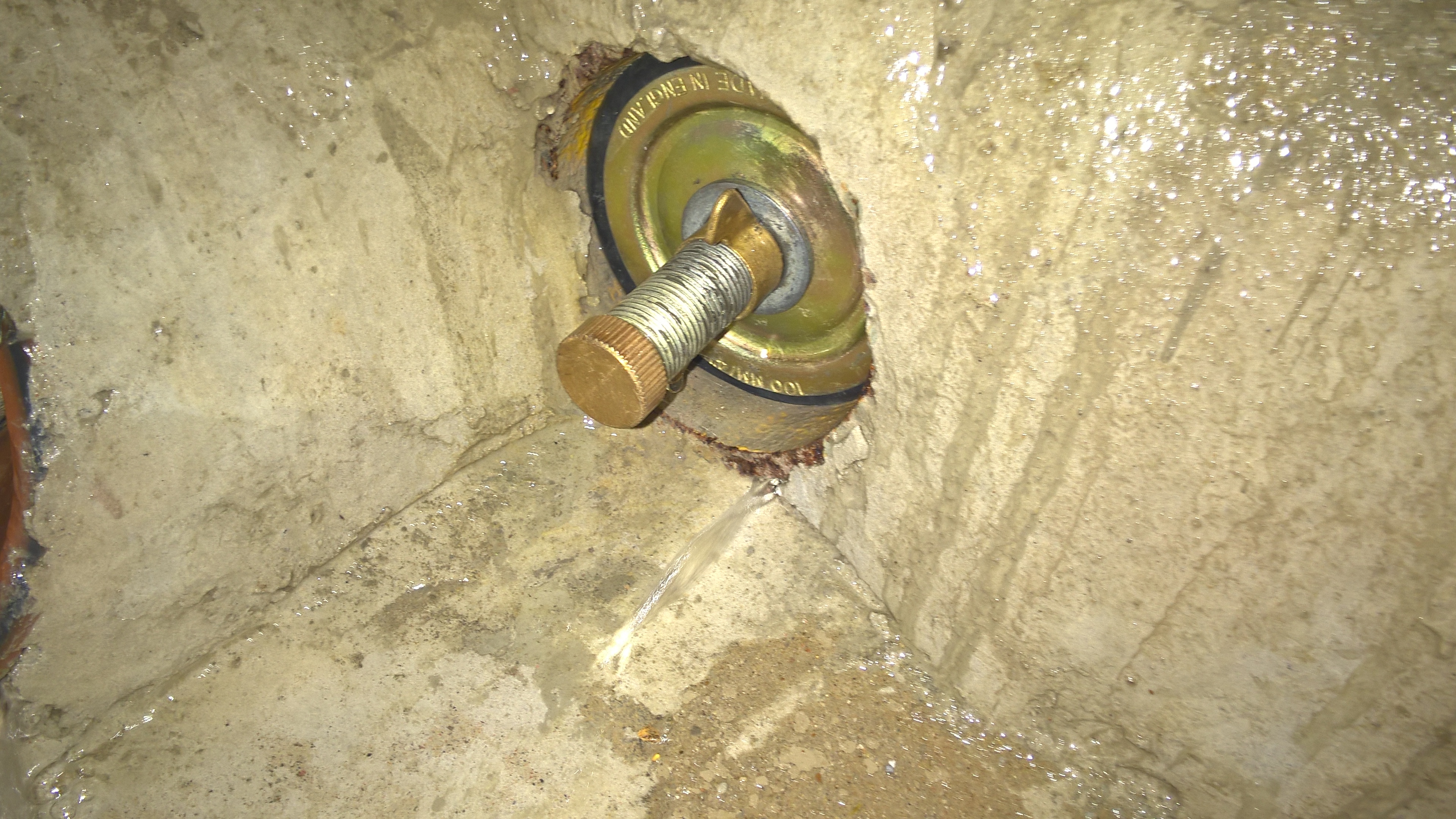
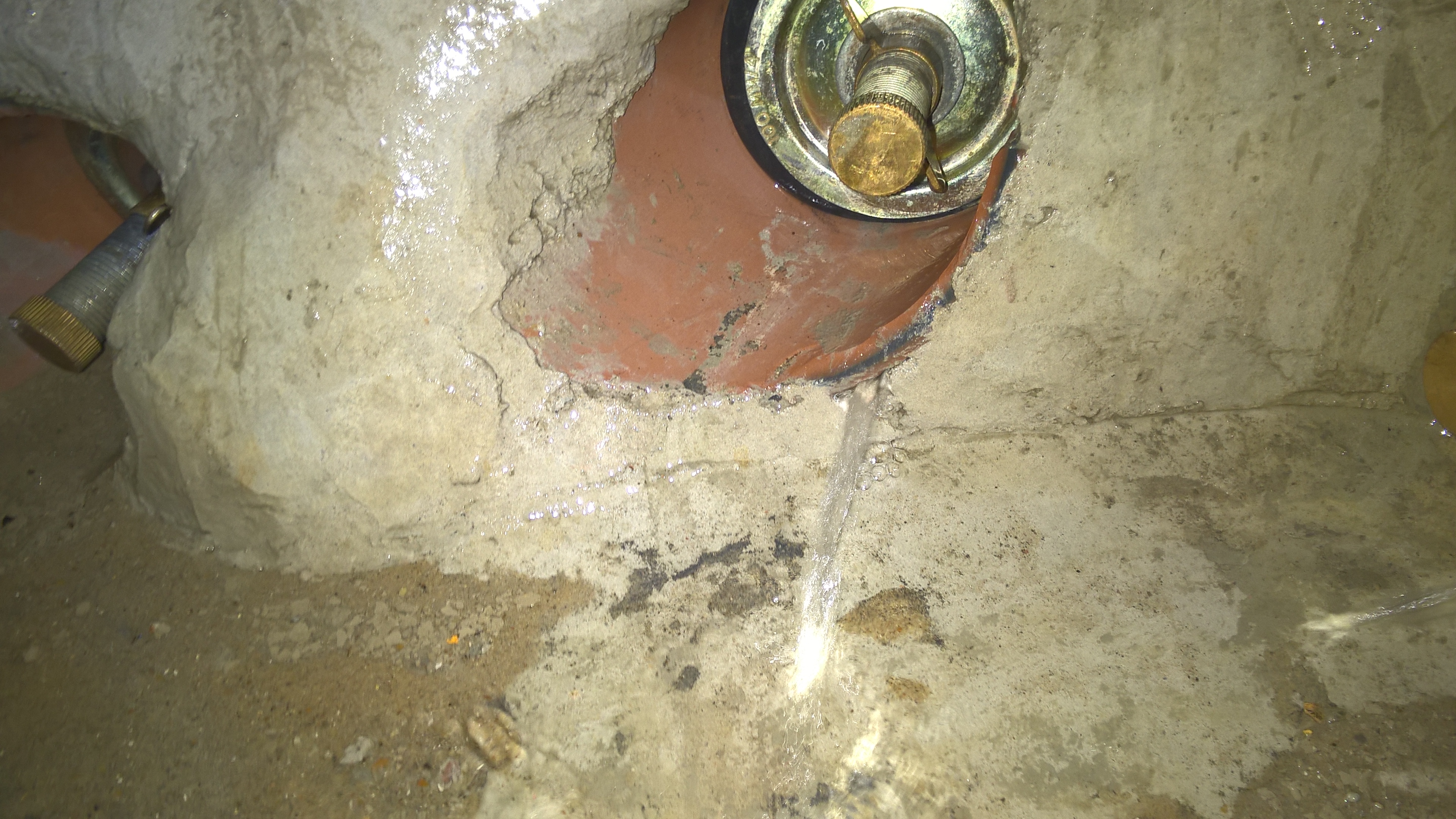
Electricity – Electricity is used for the radiant heaters, lighting (using energy efficient lamps) and all small power requirements: including the guardian’s fridge. The electricity is supplied by a small hydro station maintained by the guardian. It provides up to 10kW of power when the water is flowing well, as you can see from the picture below sometimes it runs too well!
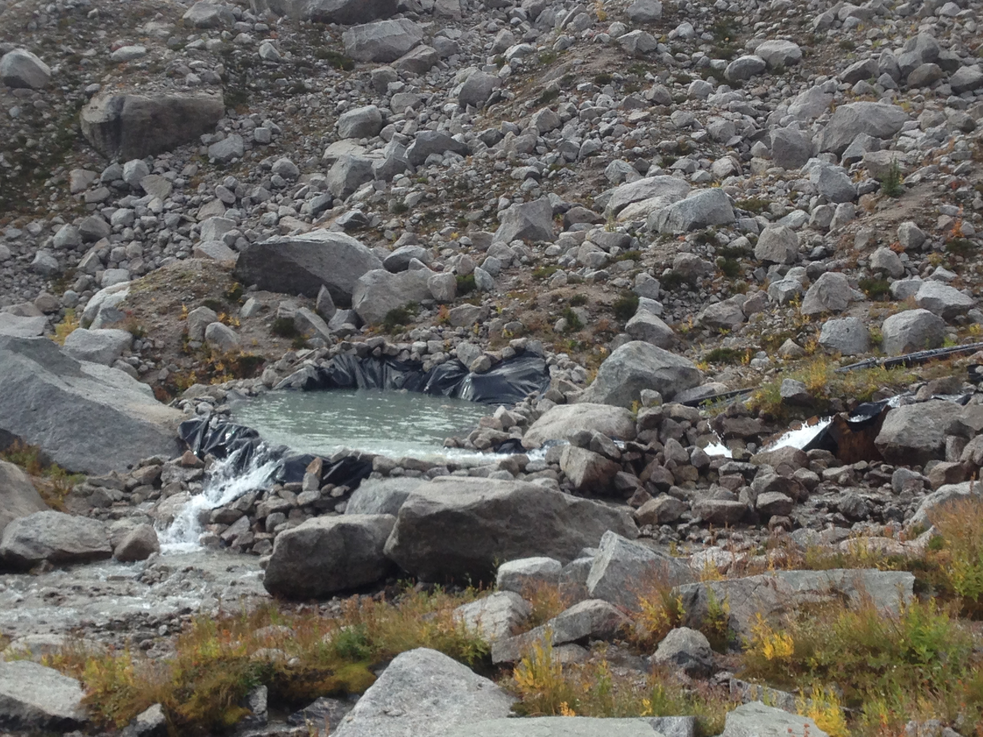
The pool feeding the micro hydro station. The dam obviously requiring some maintenance due to the weather.
I forgot to ask whether there was any electrical storage but it didn’t appear there was, that said the two hot water tanks act as a residual energy source for the heating at least.
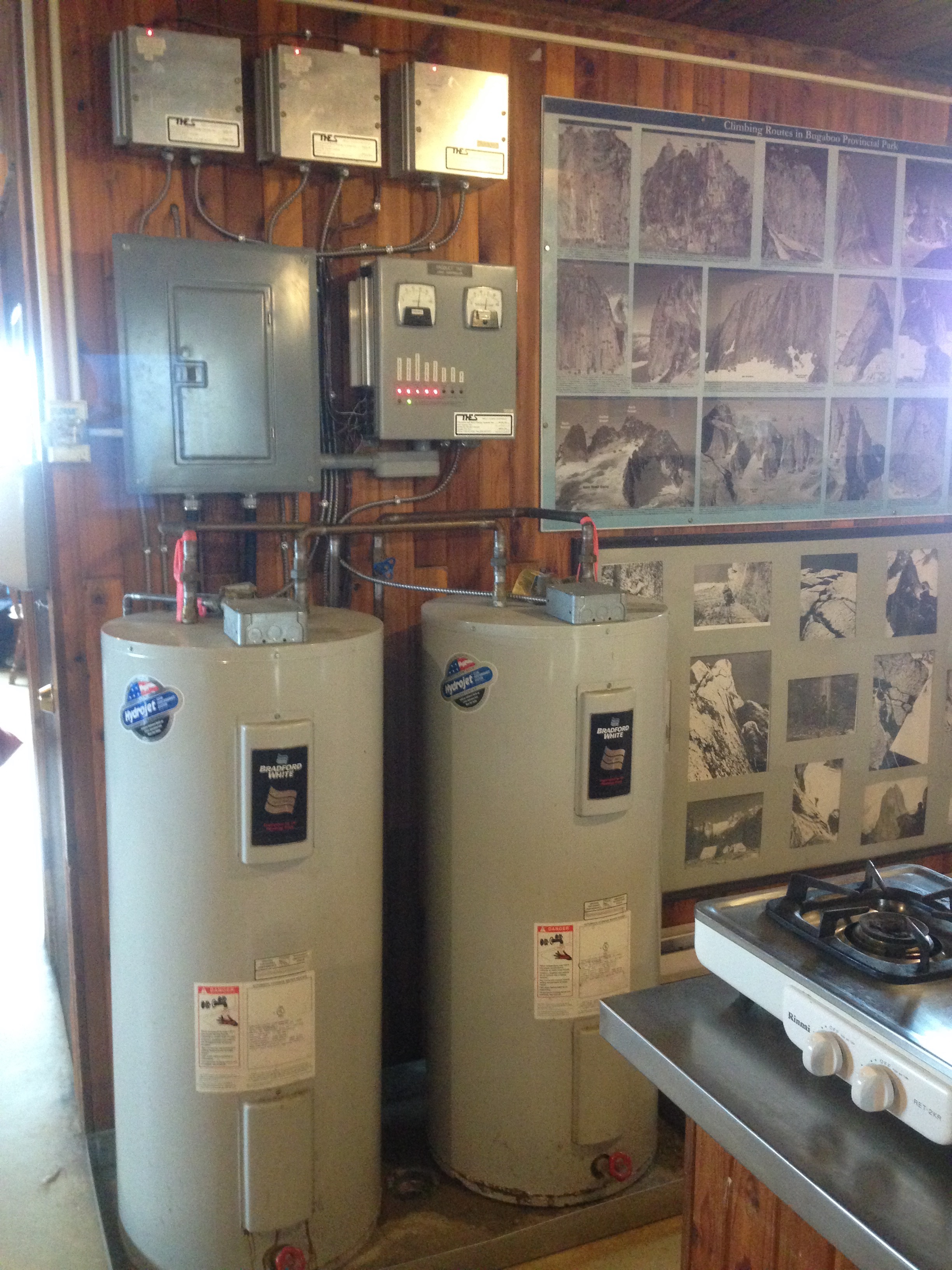
Controls and Waterheaters. Nearly as interesting as pictures of concrete…
Food – Like waste out visitors ‘pack in’ their food. The poocopter brings dried food up for the guardians on the uplift at the season change, which they compliment with fresh on their weekly commute.
So what:
To me the set up was interesting for its own sake but it also has some parallels with operational infrastructure. The human waste system seemed particularly effective as it had both a low logistical burden but also preserved the local environment. As we moved to exclusively using wag bags in some of the FOBs in AFG this barrel system would have been cheaper, logistically simpler and actually more comfortable.
Bio-engineering.
On the descent from our last route in the Park my climbing partner broke his leg, which presented a bit of an inconvenience. Fortunately with the help of a doctor and some zinc oxide tape we managed to affect a solution that was good enough for him to walk back to camp. Fortunately, for this circumstance, WO2 Whale’s right leg is prosthetic. The issue was that the grub screws holding the foot to the titanium leg had worked loose. This was despite them being glued into place. Making a stirrup of zinc oxide under the foot we then secured it in place by wrapping around the leg. More used to tubi-grips Doctor, Maj Martin-Bates made a good job of the taping.

Repairing a prosthetic leg in the field
As WO2 Whale has never had this happen before I assume the cause of the loosening of the joint was us wading through waist deep snow the day before. Usually your leg is in compression but pulling it out of a snowy hole causes some tension thus aggravating the joint and the grub screws more. The long term solution was a 4mm allen key in his tent, which perhaps should have been in is pack instead!
Finally to prove I wasn’t ‘having fun’ here is a picture of us setting up camp.

Not entirely what I had signed up for…
Winding down
With a month to go left on site I’m conducting testing of drainage, finishing off the blockwork and still arguing over builderswork.
For the phase 1s: Manhole testing is something you will likely come across and dependant on the designer will either be completed in accordance with BS EN 1610 or (as in our case) a more stringent standard defined in the designer’s specification. In this case that is imposed by the designer due to the local authority’s own more stringent standards.
Effectively we fill the manhole with water, leave it for an hour to settle (for water to be absorbed into the concrete and air bubbles to escape), top it up to the original level then start the timer. After 30 minutes we measure the drop. If it’s less than 25mm it passes, more and it fails. Failure results in issuing an NCR (Non-Conformance Report) and tell in the sub-contractor to fix it. Four of ours have failed, mostly due to leaks where the pipes are fed through the pre-cast concrete rings that form the side of the manhole. The sub-contractor is planning on re-sealing the inside using a cement based sealant that is applied to the inside by a hand trowel.
As the blockwork nears completion the M&E (that’s “mechanical and electrical” in the civvy world not “mines and explosives”) contractor has decided this is great time to alter his builderswork drawings that show where they need holes to pass their services through.
The issue with moving the builderswork is not just that the hole needs to move, but the whole fabric of the wall. Where we have a double skin wall that includes all the insulation and waterproofing, and in some cases a windpost.
All the blockwork I look after is in the basement. So why does it need windposts I hear you say?! It’s because in the temporary state the building isn’t sealed and therefore wind can get in and apply a horizontal load to the face of the blockwork. In the double skin locations the windposts and located in the internal skins (so they are hidden by finishes) with a movement joint located in the same place on the outer skin.
For those of you who are overseas: You might well be in sunny Australia or gun mad America, but I went to the Rugby World Cup opening ceremony and England vs Fiji, so in my books – I win!


For those phase 1s who are reading this while on exercise Steel: Stop it! Watch Scotland vs Japan instead!
Fame!
To follow on from Brad’s blog the internal media department have flexed their literary muscles to create this on our time with the DA and about the exchange programme. It is now hidden in the vastness of the US Army website:
Brad and I have crates available for collection at our respective houses, just come around and collect.
Offer closes 24 December 2015, all unused crates will be disposed of semi responsibly.
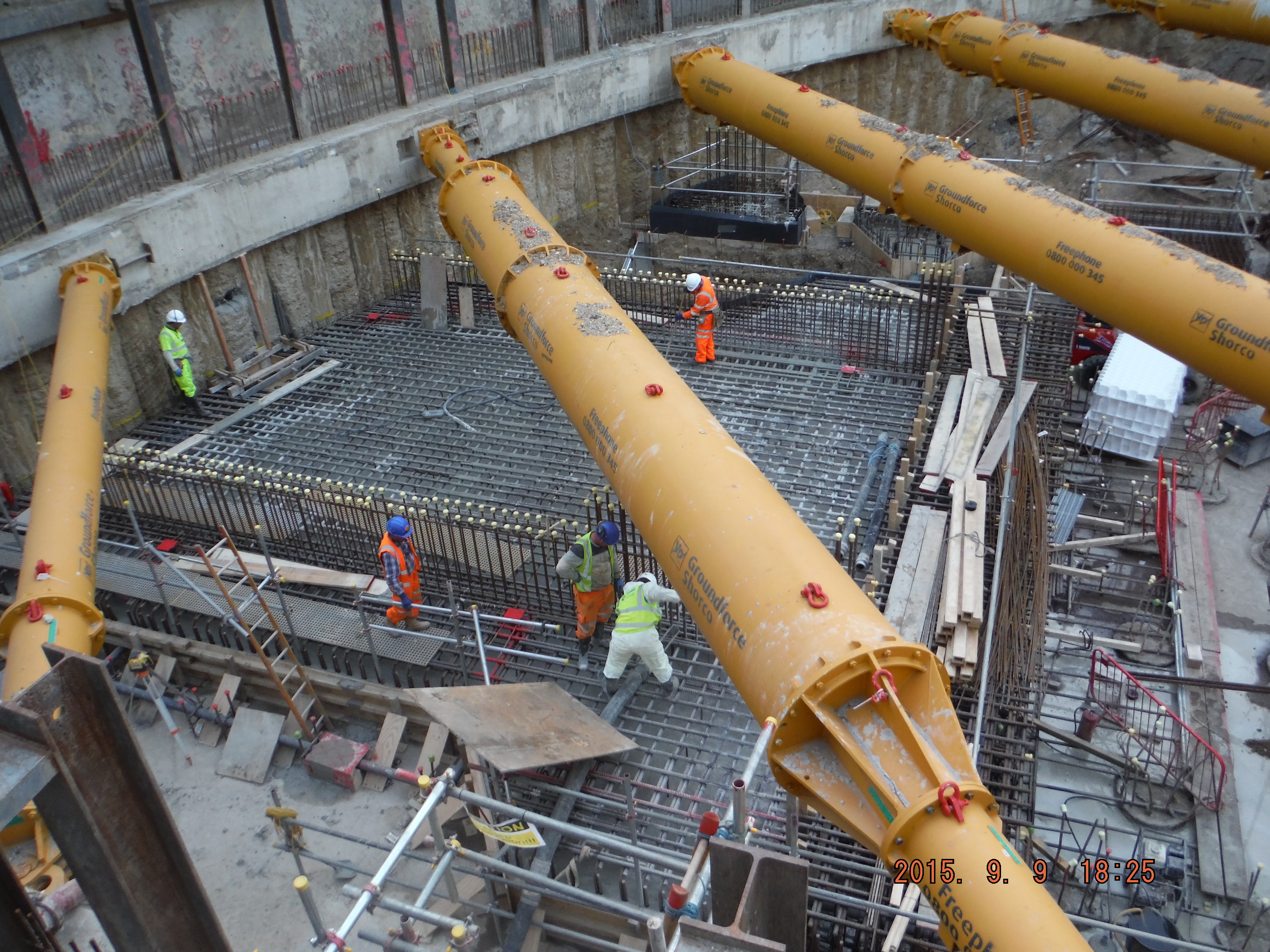
Site Two Fifty One – Drainage testing and Assessment of plunging reinforcement in piles
Site Two Fifty One – Drainage testing and Assessment of plunging reinforcement in piles
Drainage testing
As I mentioned before the underslab drainage needed testing before the concrete slab was cast. The method for this was actually very simple. There are 2 common options: air and water tests. We have done air tests. The method is to bung the openings in a run (such as gullies, rodding eye, down pipes, etc) pressurise one end with a pump to 100mm on a U tube Manometer. Over a 5 minute period the drop should be no more than 25mm. If this is the case move on to the next run, if not, test shorter sections until the leakage point is found.
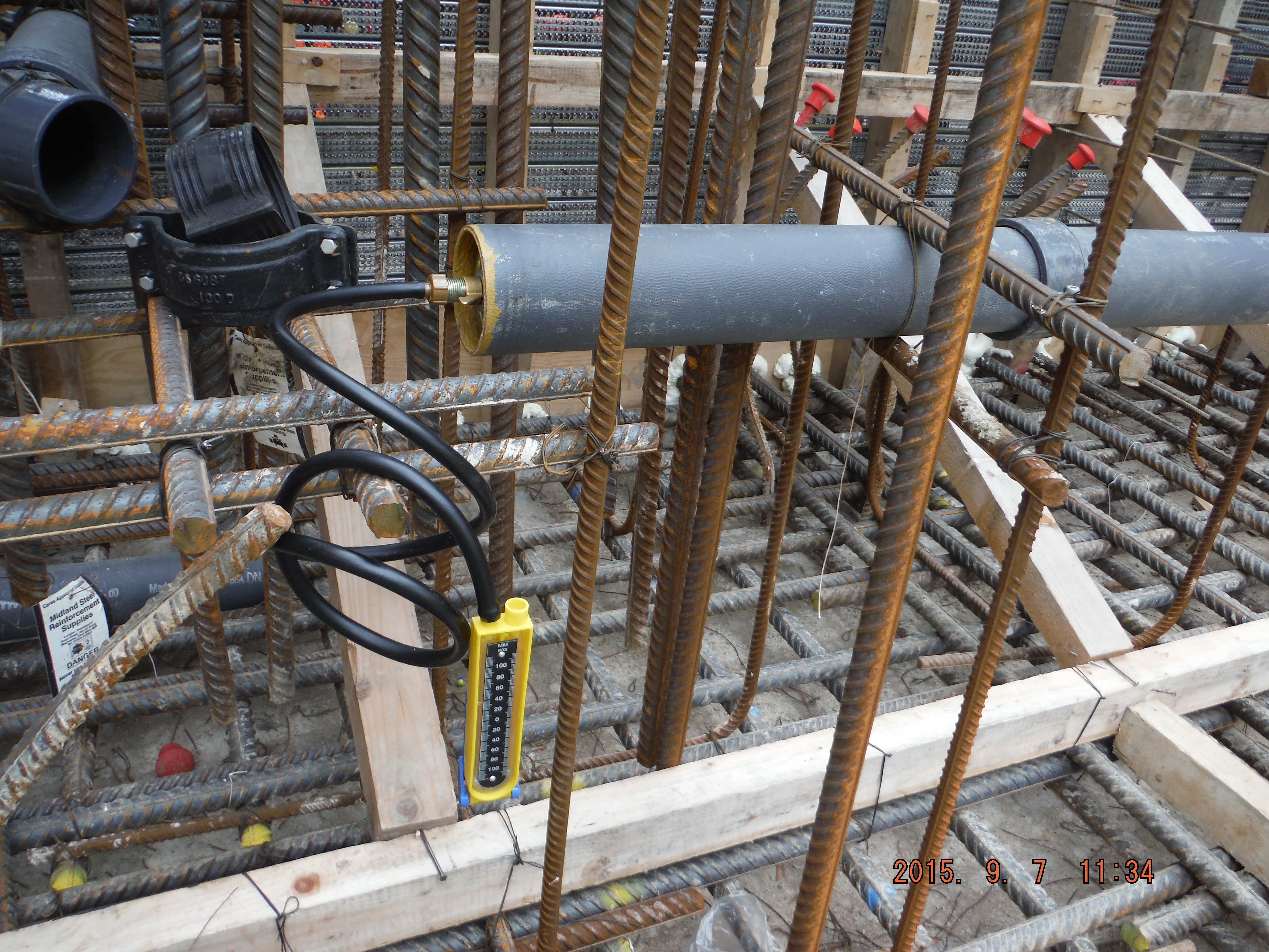
Manometer used to confirm pipes do not leak.
Tension
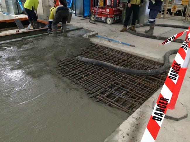
How to get tension anchorage. We have installed our first tower crane base this week. The 80m3 pour is impressive, not least because of the 0mm tolerance on the crane base but more because of the W bars used to provide tension reinforcement within the pile cap.
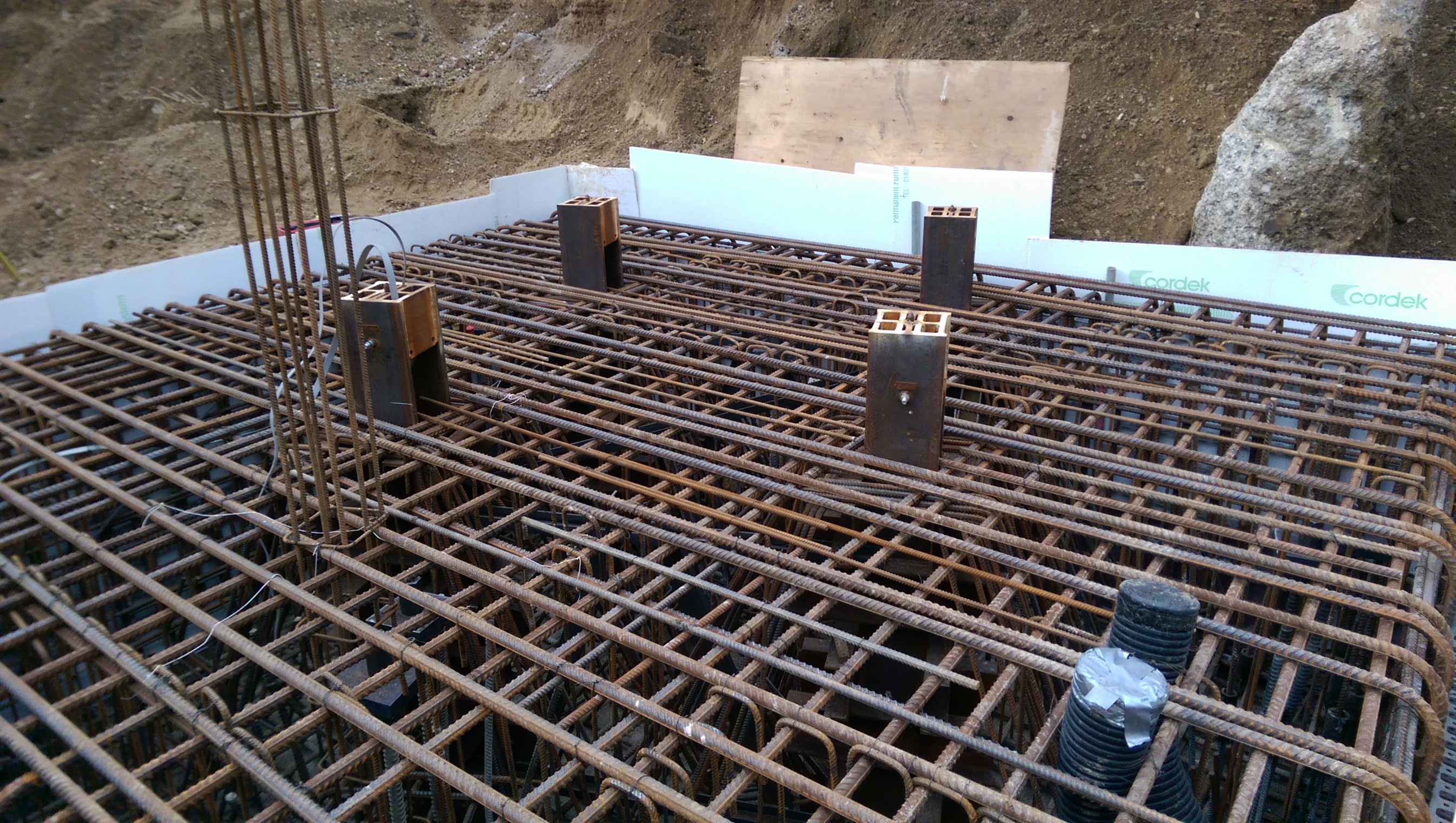
If you open this image up and look at the 4 tower crane legs you can see the “W” reinforcement.
The other interesting point is that dywidag bars the length of the piles (about 26m) have been installed to avoid the whole pile cap rotating. However the anchorage length required is greater than the height of the pile cap. To solve this, large (676cm2) plates and nuts have been used to give greater anchorage. Has anyone else seen this method used?
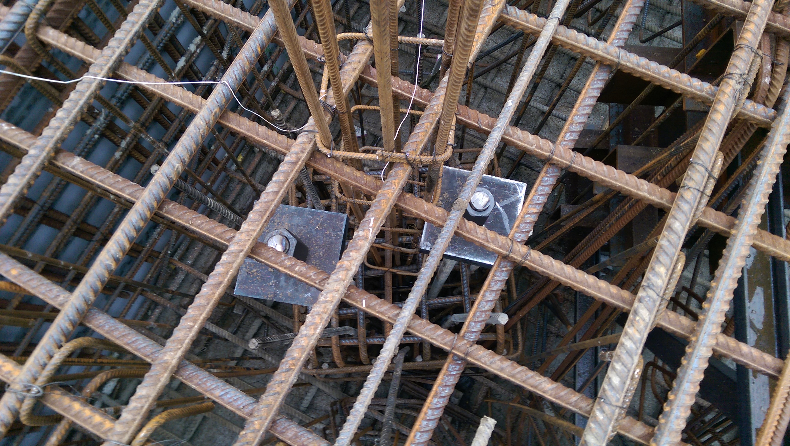
Square plates used to provide additional anchorage.
Piling methods
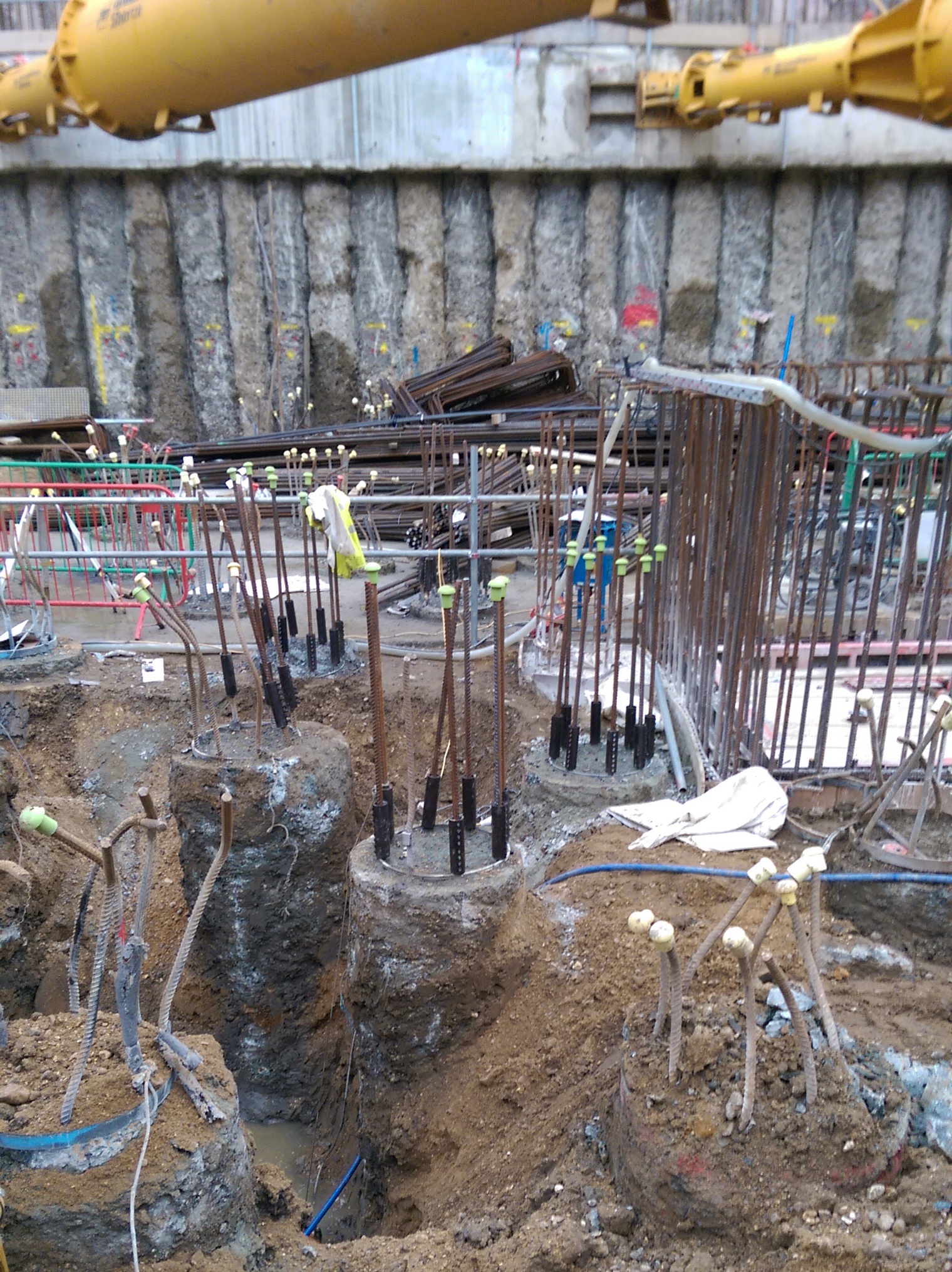
The piling method at Two Fifty One was to install piles at ground level, plunge the pile reinforcement and then excavate ground to formation level (approximately 5m lower), breaking the piles are we go.
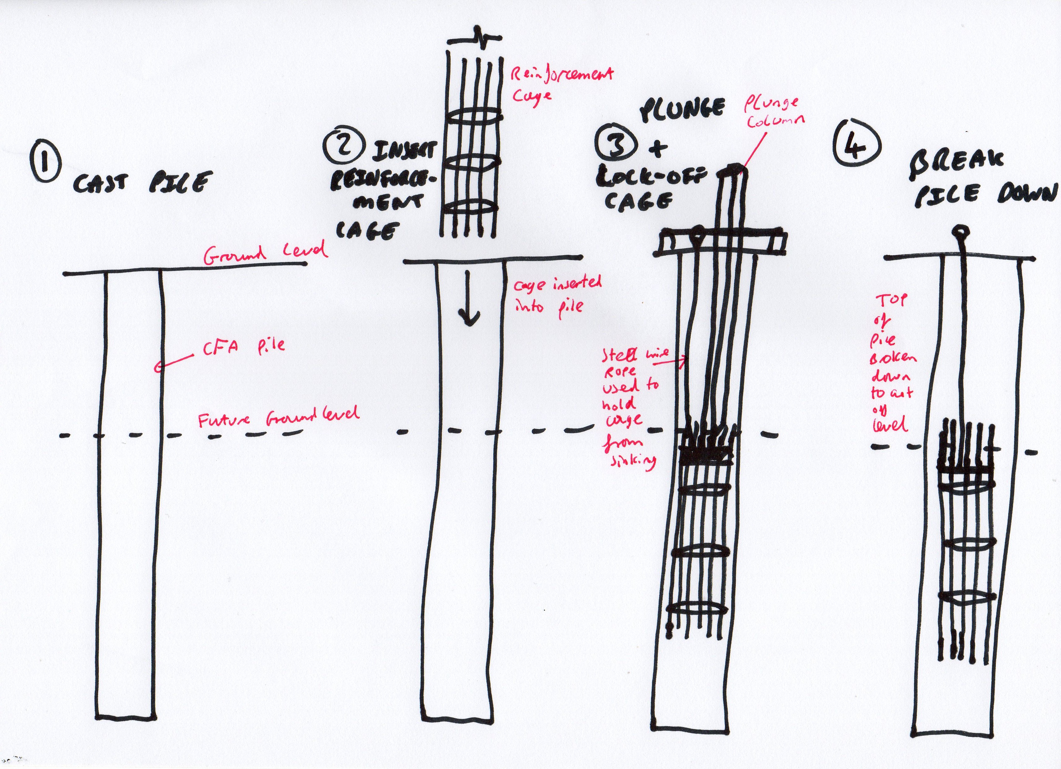
2-Year old’s impression of plunging pile reinforcement cages
This has a significant disadvantage. Let’s assume 300 piles, 5m waste, 0.75m diameter, £140 per m3 of concrete equals a little under £100k in waste concrete, plus time to break piles, plus muck away time.
However the advantage is that the piles can actually be installed. If the site was deeper the props would be in the way of the piling rig and getting the rig out of the site would have been pretty tricky. Bearing in mind the piling package was about £4M, this represents a 2.5% fraction of the cost.
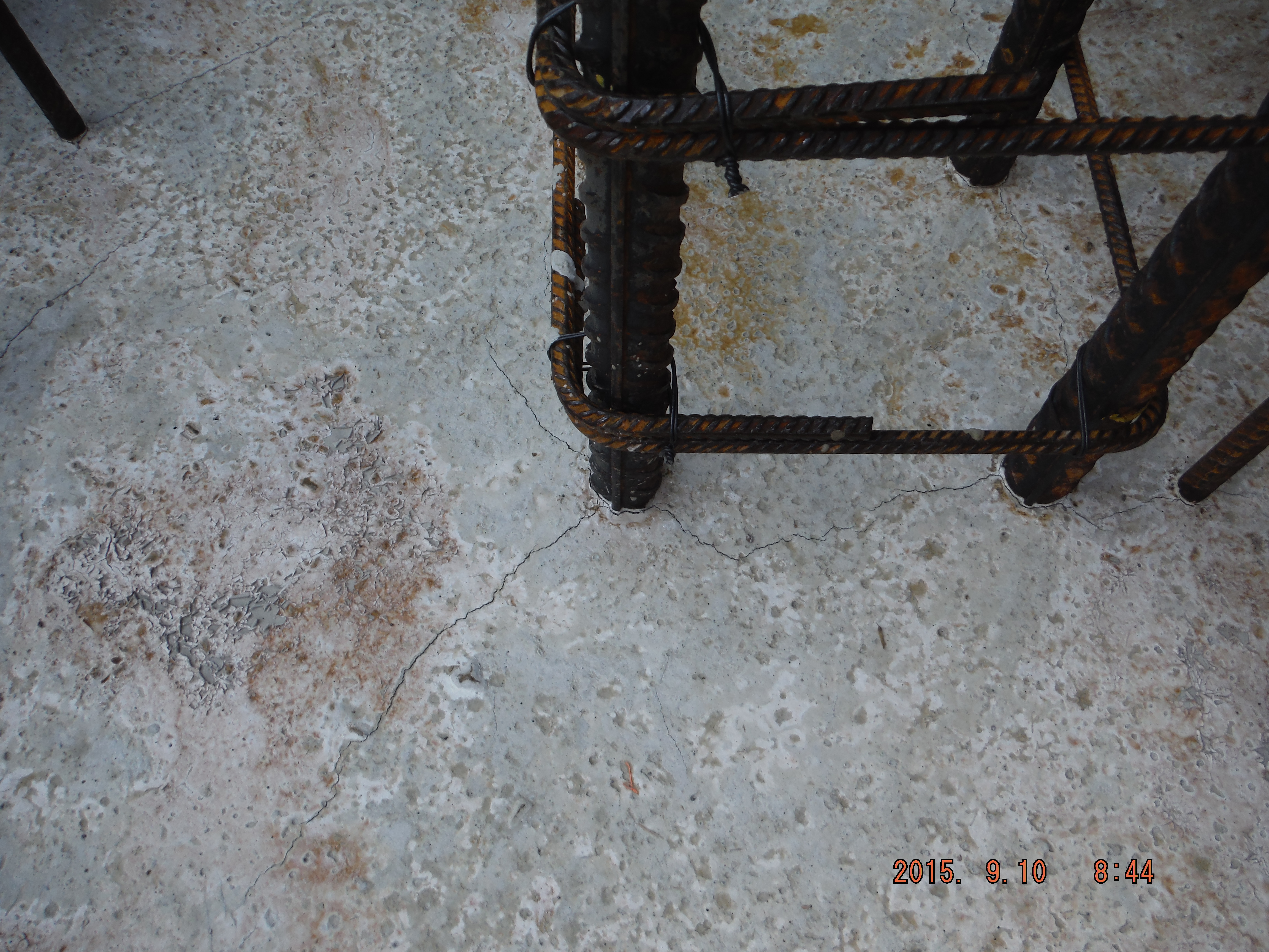
Further issues. Submerging pile reinforcement cages to an exact cut-off level means it was not done very well. Mostly are within tolerance for anchorage requirements but some are too low.
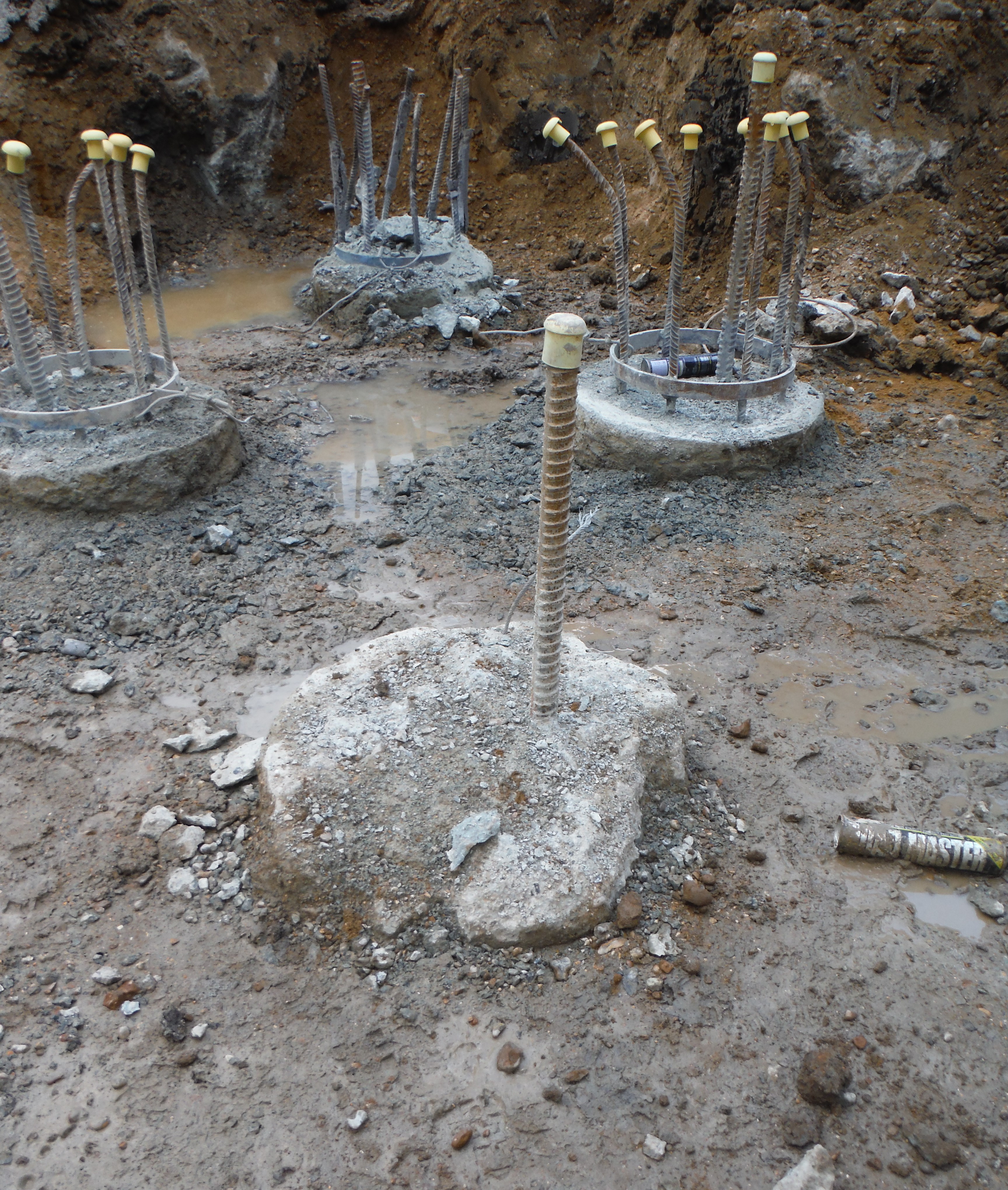
Spot the difference – something is not right about this pile…
Moreover, in order to dig deeper pits we have had to cut some reinforcement down (to facilitate excavator arm length reaching to dig level). Therefore to extend the reinforcement back to the correct length couplers have been used. Bar diameter dictates coupler size. The common MPT couplers seem to be what everyone has heard of, they are British Board of Agreement approved, but unfortunately not Certification Authority for Reinforcing Steels (CARES) approved. Laing O’Rourke only allow CARES suppliers – due to adhering to certain quality standards and also as a wider corporate image piece. Therefore once this hurdle was overcome, the couplers were installed. As a final point the locking bolts should shear off to demonstrate correct installation.
Couplers used to extend pile reinforcement.
Oz PCH – Helicopter Noise Attenuation.
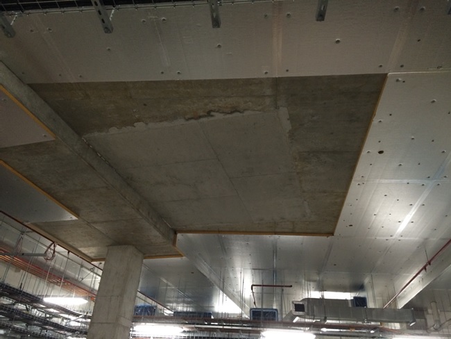
This pic is to entice the civils to read my blog…more on this at the end.
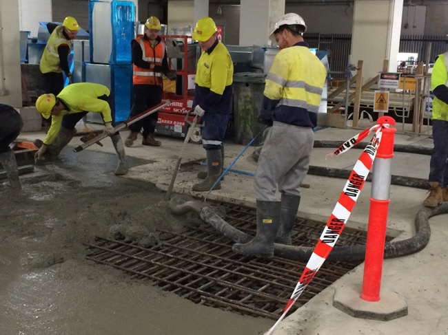
Fig 1. Concrete Pour in the Basement.
Introduction
This blog aims to discuss the potential issue of helicopter noise being carried throughout the building using the ductwork as a noise passage/channel. It also covers the attenuation used for the back-up diesel generators.
Problem
The helicopter pad was procured as a packaged unit but there seems to be a scope gap for ownership with its commissioning. That aside, the acoustic consultant for JHG stated a helicopter using the HLS (red line in fig 2) passes directly over AHUs housed in two non-acoustic out-houses (yellow line in fig 2) and produces noise levels of around 105 dB(A) as a point source. The (A) refers to the A-weighted sound pressure level which approximates the human ear’s sensitivity to sounds of different frequencies. Without this filtering, calculated and measured sound levels would include sounds that the human ear cannot hear, such as dog whistles (high frequency) and sounds made by large buildings with changes in temperature and wind (low frequency).

Fig 2. Aerial View – HLS (red line) AHU Out-houses (yellow line).
For comparison table 1 indicates where 105 dB(A) sits amongst other familiar sounds.
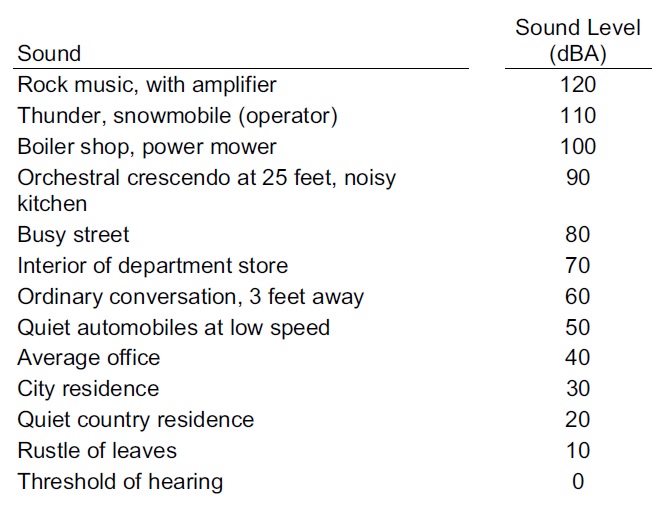
Table 1. Common Sounds on the A-Weighted Decibel Scale.
These particular AHUs, supplying conditioned air to the Theatre Department, have been placed outside on top of the plantroom as they wouldn’t fit inside due to layout design changes. This places them in close proximity to the rooftop HLS and are only covered, for weather protection reasons, by a non-acoustic out-house structure. Fredon, who are the plantroom mechanical fit-out subcontractors, have stated that there may be an issue with sound levels in the Theatres and that they have to conduct an assessment of the noise levels produced by a visiting helicopter to determine how much sound will travel down the air-conditioning ductwork and if they comply with the performance standard at the outlet grills.
So What?
Fredon were aware they had to conduct their own acoustic performance tests, highlighted at tender, as they knew a HLS was a design package; the situation now becoming more problematic with the re-location of the AHUs outside of the plantroom. Fredon should have factored-in the acoustic performance testing when the re-design took place instead of leaving it till now, once the ductwork installation is complete.
Solution and Possible Implications
They now need to conduct the acoustic performance test and if they don’t comply they will have to fit attenuators into the ductwork in order to reduce noise travel, commercially this will be at Fredon’s expense but could potentially hold-up commissioning and may incur delay claims from JHG. The impact could be reduced if they can fit attenuators in the plantroom directly below the AHUs on top and this would cause the least pain in terms of cost and time delays but it will depend on how much attenuation is required and how congested the plantroom is already; the alternative being to fit them further downstream in ceiling voids, that are already closed up, but this is something we and Fredon would want to avoid if at all possible.
Fredon are waiting for confirmation of the noise criteria from the design consultants NDY before continuing with the test. NDY are waiting for the client to sign-off a design departure for the criteria laid out in table 2 (red box).
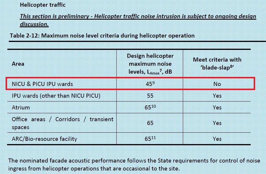
Table 2. Max Noise Level Criteria during Helicopter Operation.
NB:
7 Typical values generated by helicopter movements along defined flight paths.
8 ‘Blade Slap’ is the sharp cracking sound from helicopters, typically occurring with turns, shallow descents and flare approaching a hover.
Performance criteria are provided in Table 1 on the basis of data and modelling obtained with blade slap characteristics included.
9 Assessed in terms of the continuous equivalent LAeq level. To comply with 45dB LAeq(15 mins), the LAmax (slow) is to be less than 55 dB(A) or it can exceed LAmax (slow) 55 dB(A) for 6 minutes per hour. Further LAmax should not exceed 65 dB(A) at any time.
How Attenuators Work (Simplistically)
In simplistic terms, when fitting an attenuator in line with ductwork it requires a larger space than just the original ductwork. Fig 3 shows this including the tapered sections either side of the attenuator.
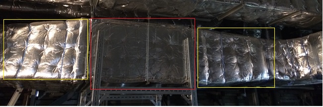
Fig 3. Attenuator. Red box showing the attenuation section with the two yellow boxes showing the tapered sections.
Theoretically and in practice an attenuator works by the noise being absorbed by the acoustic filler (wool mixture) in the solid sections with gaps between to continue to allow air flow. Due to the sections taking up space (around 40%) of the duct volume, the air velocity increases. This increased velocity creates its own noise termed ‘regenerated noise’. As long as the net noise level has reduced it is considered worth doing but engineers can get caught in the trap of the law of diminishing returns due to the increased pressure losses caused by the reduction in volume. This is caused by a pressure change/differential between the point before and after the attenuator. This results in second and third order effects of requiring a higher fan speed to overcome the pressure losses and then requiring a bigger fan motor which uses more electricity. A way to resolve this is by maintaining the pressure over the attenuator which can be achieved by ensuring the attenuator is the same volume as the ductwork leading up to it. Due to the space taken up by the acoustic filler sections inside the attenuator, means that the overall dimensions of the attenuation section has to increase, as shown in fig 3. Sometimes this causes issues if there is limited space in a ceiling void.
A Different Example – Diesel Generator Noise Attenuation
I had a look around one of the 3 x 1.25 MVA back-up diesel generators to investigate its noise attenuation design.
The generators, manufactured by Cummins, are housed in individual acoustic and weather protected containers.
Inside the container, at both ends, are the attenuation sections as shown in fig 4. These are vertical sections (red line) with a permeable membrane filled with acoustic noise damping wool. At this end outside fresh air is being drawn in (blue arrows) by the generator radiator fan but the noise is escaping (yellow lines) through the gaps between the acoustic sections.
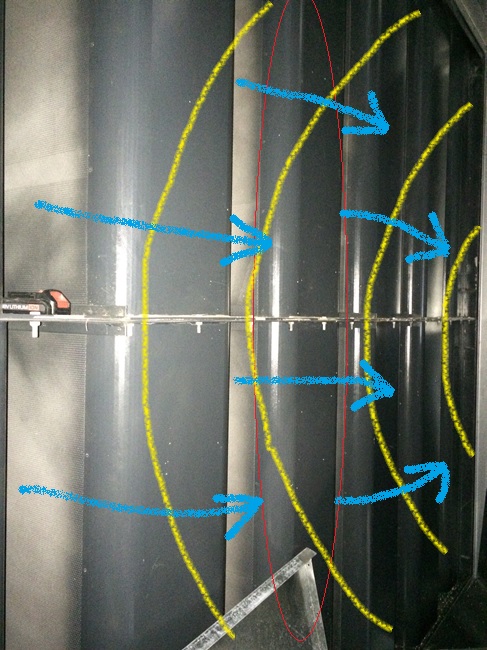
Fig 4. Generator Attenuator Section – Radiator Fan End.
Fig 5 shows the incoming outside air (blue arrows) and the noise path (yellow lines) taken as it bounces between the two acoustic sections losing noise as it passes through the acoustic material and finally out the louvres at the end.
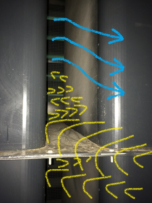
Fig 5. Generator Attenuator Section Working – Radiator Fan End.
The capping louvers at the container end have acoustic foam attached to the underside of each horizontal louver and so also acts to reduce noise coming out (yellow lines in fig 6) but allows fresh air to be drawn in (blue arrows).
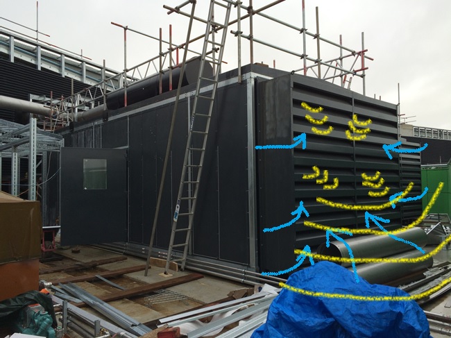
Fig 6. Generator Louvre End Capping.
We are currently waiting for the generators to be run-up and tested with the installed fuel supply system and for all three to be tested for load sharing as part of system commissioning. Until that time we cannot fully test the acoustic noise levels produced.
Useful References
BSRIA – A Guide to HVAC Building Services Calculations (2007) (second edition) p.125 – 133, describes the acoustic calculations required in design, in particular ductwork noise transmittance.
CIBSE Guide B – Heating, Ventilating, Air Conditioning and Refrigeration (2005) – Section 5 Noise and Vibration Control for HVAC p. 5-1 to 5-22.
In Other News
For the civils, the below pics are from the final basement concrete pour filling the ground slab where one of the tower cranes once stood. Fill your boots to ask questions but I most likely won’t know the answers…I just took the pictures!
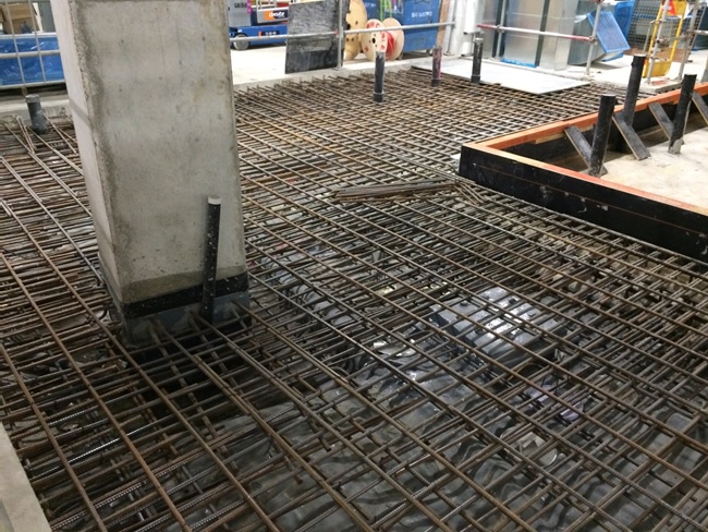
Rebar, Form Work and Tower Crane Bearing Pile
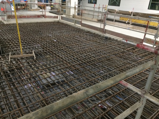
Rebar and Tower Crane Bearing Pile
Previous above Slab Aperture for Tower Crane
Concrete Pour

Finished Pour Levelled
And finally…speechless!
Erection Plans, Payments, and Visits
Following on from the cryptic erection plan for the steel truss roof a meeting was called; the contractor was livid that their plan had been E coded. The start of the meeting was uncomfortable to say the least, but when we got into the crux of the meeting, ie them talking us through their plan it was evident that there was confusion even between the sub-contractor and the principal contractor as to what was going on. In the end the USACE contingent didn’t have to say much.
Whilst I have no doubt that the very experienced sub contractor would have been able to build the truss, and would have done so safely, probably – if we hadn’t insisted on a properly thought out and communicated plan that was understood by all it would no doubt have been a lot more painful. Simple things like staging areas, order of material delivery to site and sequencing may have gone wrong, resulting in on site fixes to get the thing up. The new plan was submitted while I was away and is much better, essentially being an isometric contract drawing that is coloured in to indicate different stages of construction with notes.
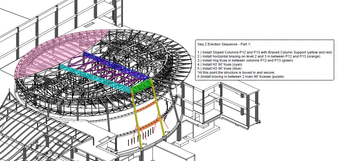
Example erection plan sketch
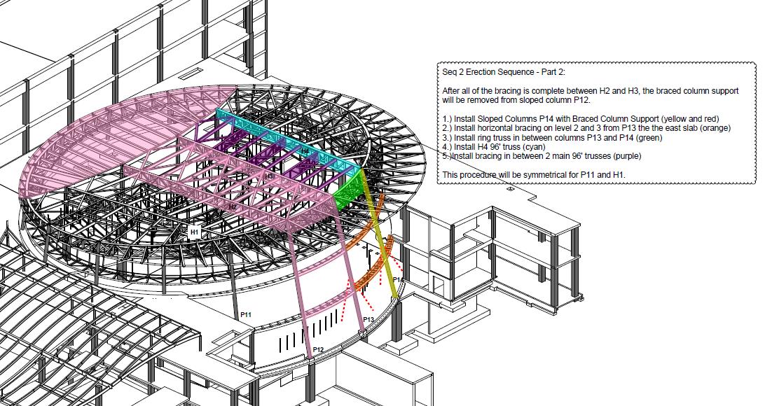
Example erection plan sketch
Although the document is still not paginated (chinned me right off) the step by step process is crystal clear through the use of drawings as included above.
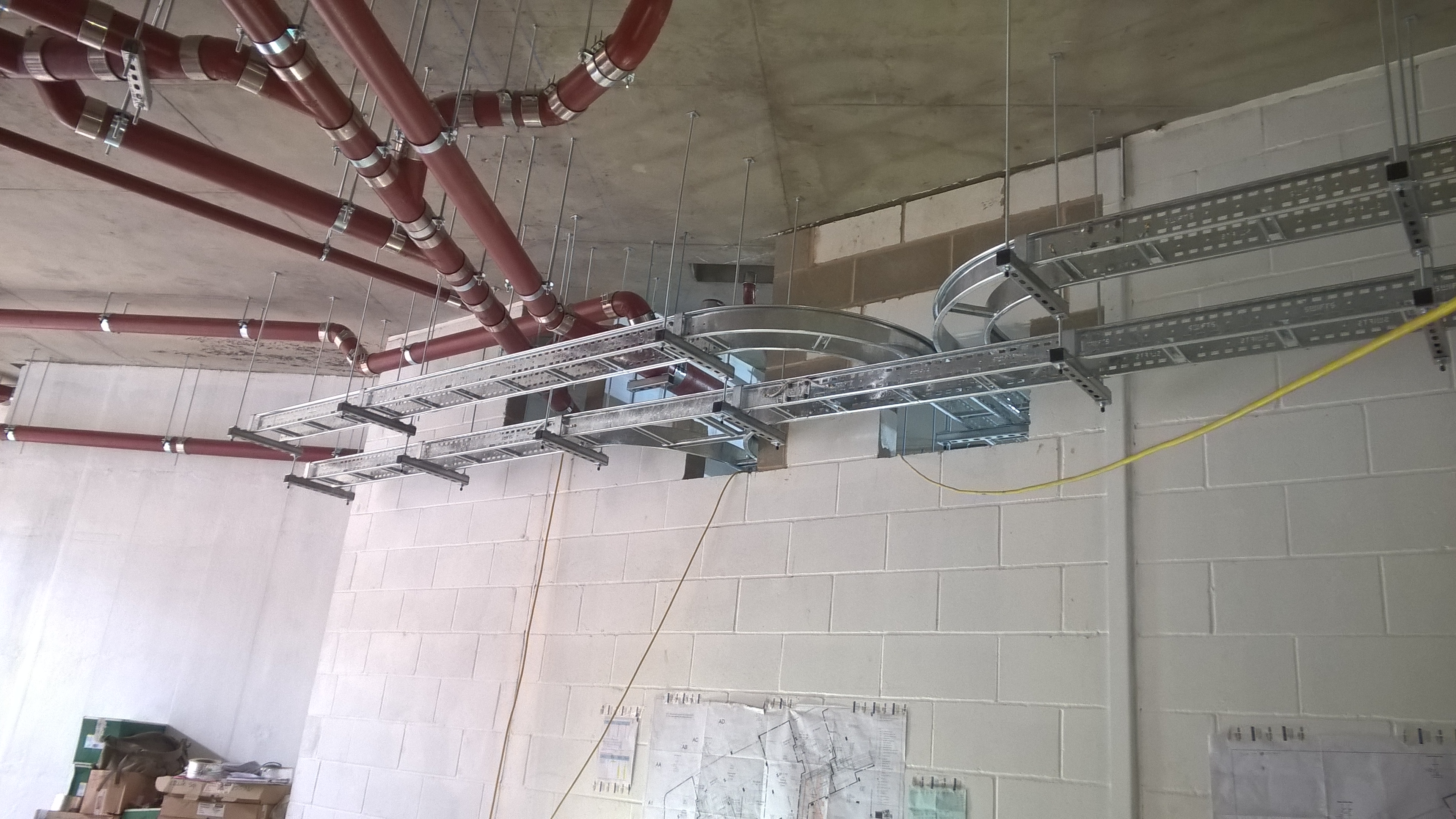
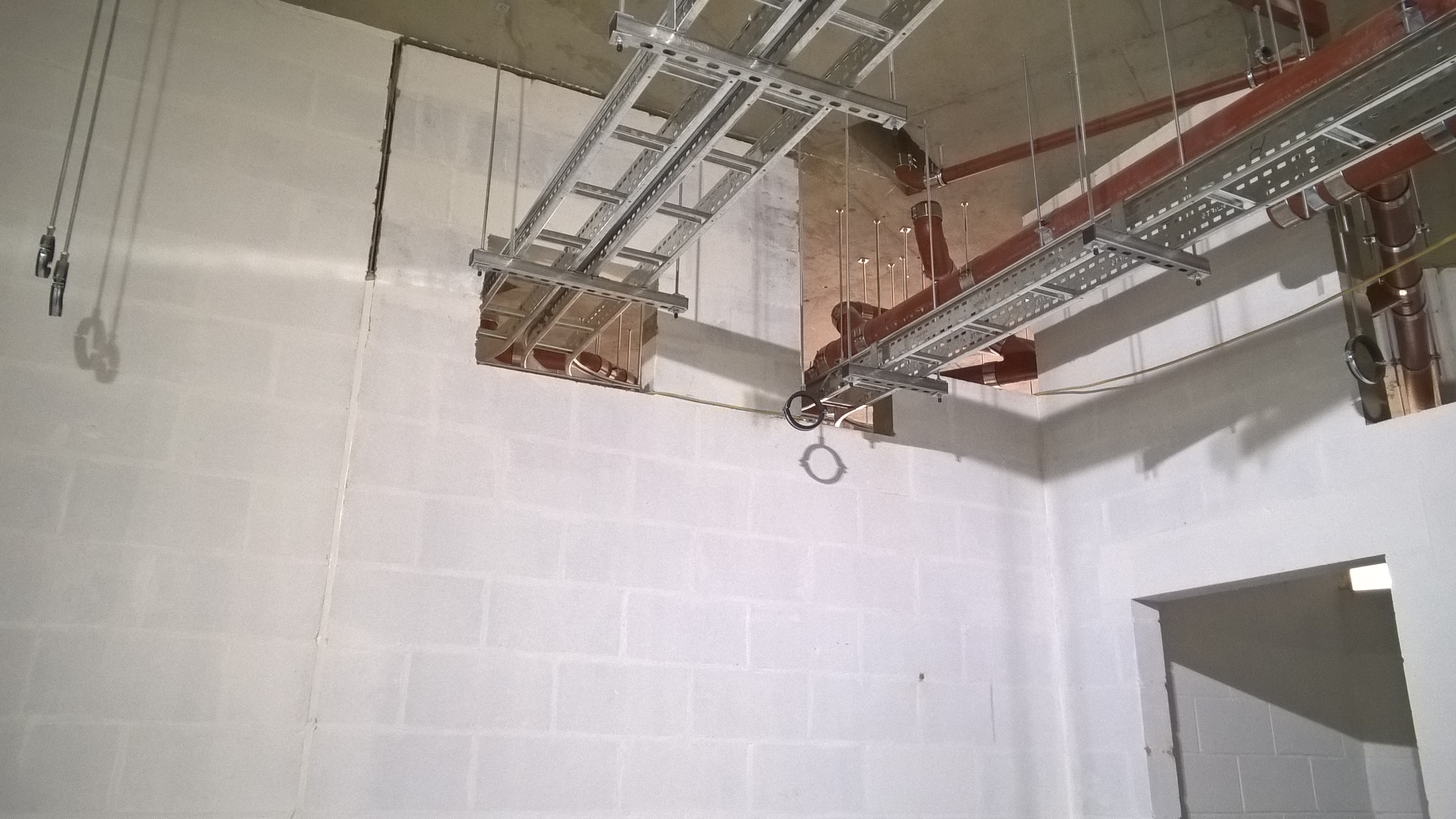
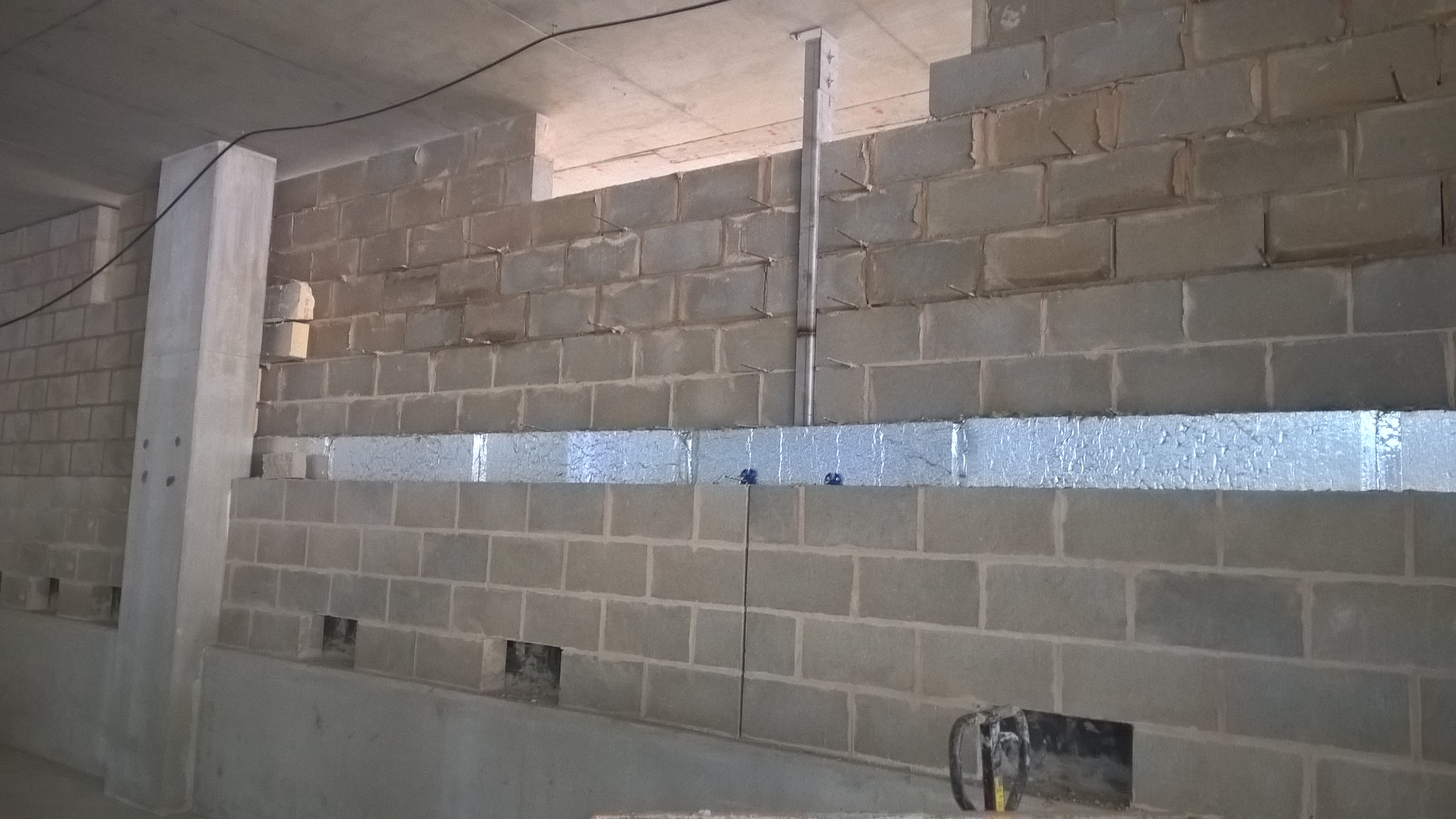
Whilst I was away the CUP was pretty much completed (structurally) and is now a mass of Mechanical, electrical and Plumbing (MEP) hangars and Concrete Masonry Unit (CMU) walls. The CMU has a lot more to it than I thought and has been fairly interesting to see, but so far only minor deconfliction issues have arisen.
I’ve also got involved with the site ‘pencil walk’ to determine the percentages complete of on site activities and ultimately the payments to the PC. This process starts with the PC who submits their proposed percentages of works complete for the month to USACE. We then verify the percentages and negotiate discrepancies with the PC. I was surprised at how amicable this was, especially when I knocked back a few estimates. Some of the ‘agressive’ percentages are a floor in the system, which has a given data date by when percentages are required. This is not at the end of the month, and so field engineers are required in some instances to estimate how much work will be completed by the end of the month.
The agreed percentages are put into the cost loaded schedule and a narrative produced by the PC. This is agreed once and for all by the Contracting Officer who then agrees payment in the sum of whatever the monetary value of the percentages complete works out to be. The updated schedule is then published with the output being the ability to track the progress of the project in terms of project finances. By comparing the actual S curve to the baseline S curve you can get a feel for how the project has/is progressing and make assessments about manning levels and payment dates as well (payment requests are made 90 days before 85% of the funds are used up). The process is lengthy and requires considerable input to mitigate the risk of the PC over/under estimating his work but the utility of the output is in the ability to accurately report progress. The downside is that the most up to date conformed schedule is a month behind!
Another snippet that I gleaned is a floor in the proposal stage. At tender all the contractors submit a cost loaded schedule as part of the tender package. This is, for one, so that USACE can assess that the project can be built on time. The schedule is required by the contract to conform to a number of specification requirements, such as nil redundant logic, must be cost loaded, costs for procurement are to be included in the installation activity (to encourage performance), must be in the approved programme etc. This conformity, however, is not checked as part of the proposal grading when USACE is selecting a contractor to complete the works. This is interesting because the initial schedule is required by USACE 30 days after contract award as part of the pre-construction submittals. It is at this stage that scheduling issues are highlighted. An example of this issue is highlighted by one of the other projects on site which was recently awarded. Their initial schedule, and the one which they used to win the contract, has been rejected because it doesn’t conform to the specification and so they are having to resubmit as part of their pre-con submittals. To USACE its a bit of a non issue, because the contract has been awarded for a set price and duration, however it can put the PC on the back foot from the start. Fortunately though, the sooner you get behind the longer you have to make it up.
I’m also mid way through writing a Basic Change Document (BCD). This will alter the scope of the initial contract based on realities of site conditions. Initially the client wanted all underground power to be concreted in (in red concrete), including the electrical ducting to all the site lighting. Congestion of utilities across the whole site has led to a re-think of this requirement. The 3700 yards of schedule 40 piping initially specified has been up-scaled to schedule 80 piping but the requirement to concrete completely removed. This was after negotiation with the client who agreed based upon the likelihood of conflicts and the required time to place. The numbers are not yet confirmed yet but, across the whole site, there will likely be a $200,000 credit for the client and the relief of some un-needed headaches for the PC. I can’t help feel that if somebody had checked with the client at an earlier stage, that he actually meant ALL electric utilities should be concreted in, this might have been averted.
In other news: This.
The Defence Attache visits the site.
And this.
President Obama visits the site…
Which was interesting, not least because the entire job site was shut down for his arrival on half a days notice from the Client. Cue the e-mails from the PC requesting adjustments for delays. Fair one.
Two Fifty One – Curing Methods
Two Fifty One – Curing Methods
On Wednesday we did our first large(ish) concrete pour (225m3). This was for the basement raft and 2 pile caps. The aim was to fill the 2.1m deep raft (large pile cap) to underside of slab which will be formed across the entire site (450mm thick, to be cast in waterproof concrete). The setup was a mobile pump at the end of our pit lane which involved having concrete wagons back onto the pump. Luckily the front of the vehicle was far enough away from the road to avoid any road traffic accidents.
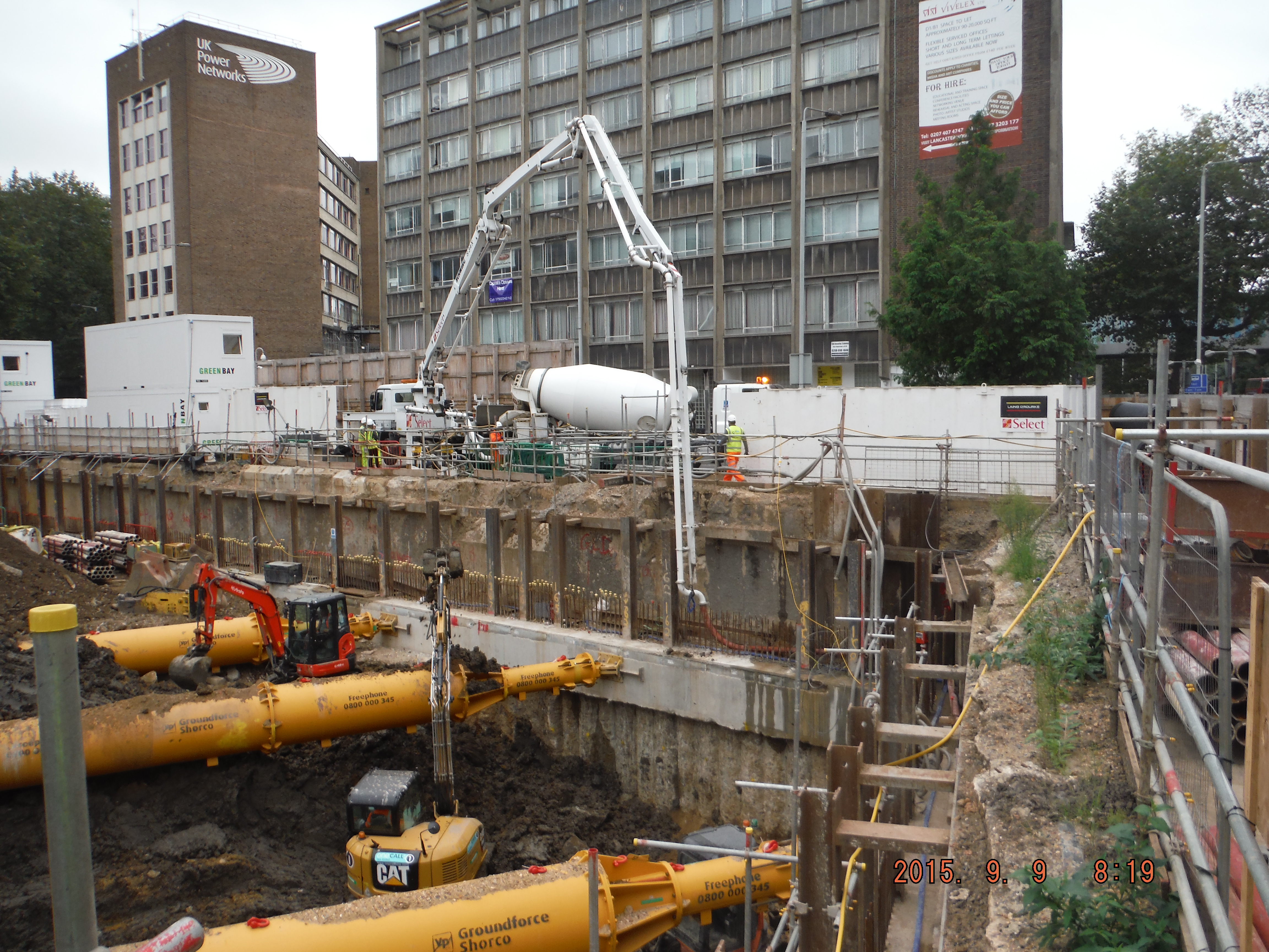
Pump positioned within the site, concrete wagons backing onto it, just into site. The pipe line then ran around along the capping beam and down to the pour location.
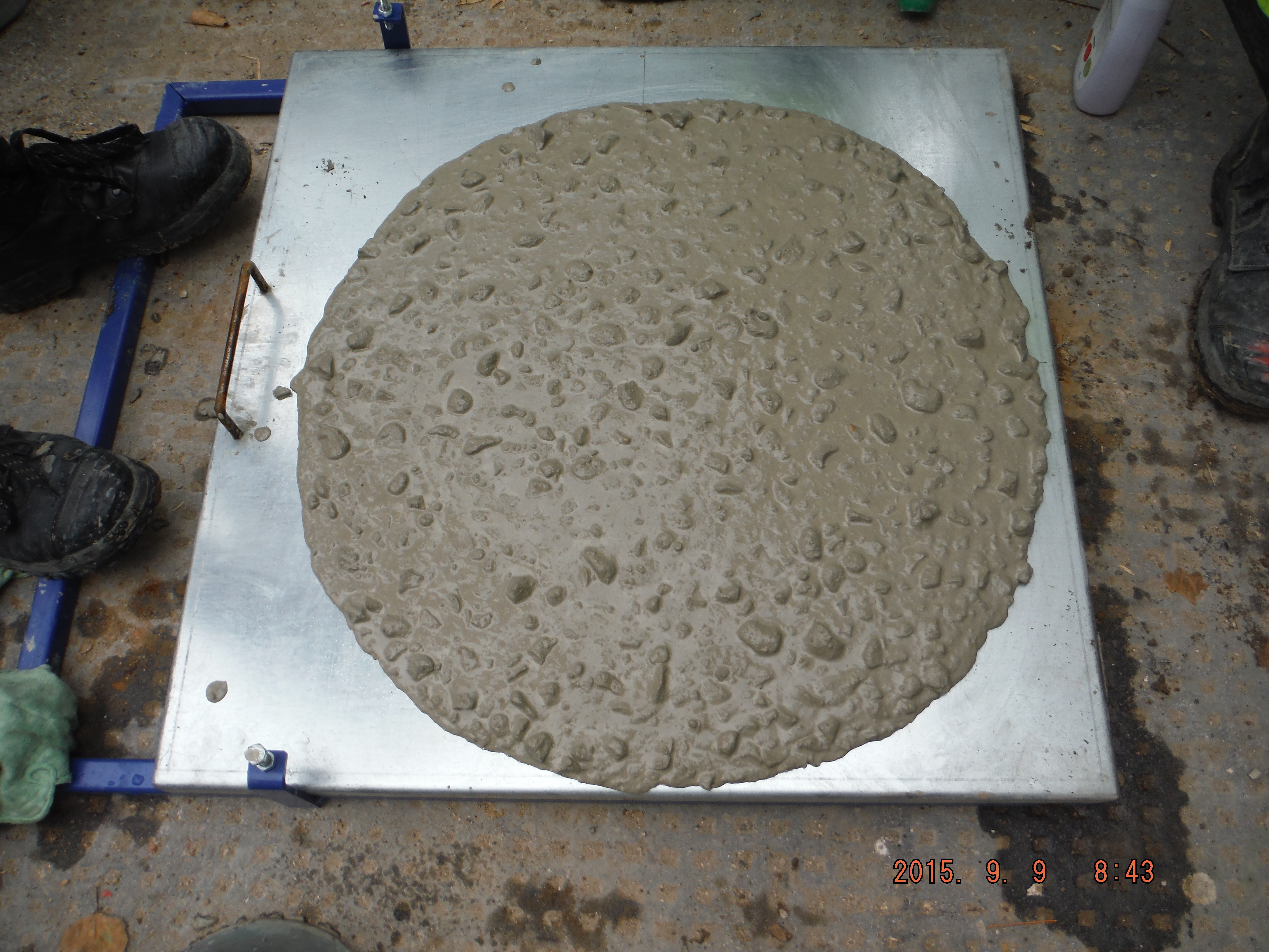
F5 consistence – therefore flow table tests. Interestingly the test was repeated after 4hours and it achieved just a 20mm lower radius.
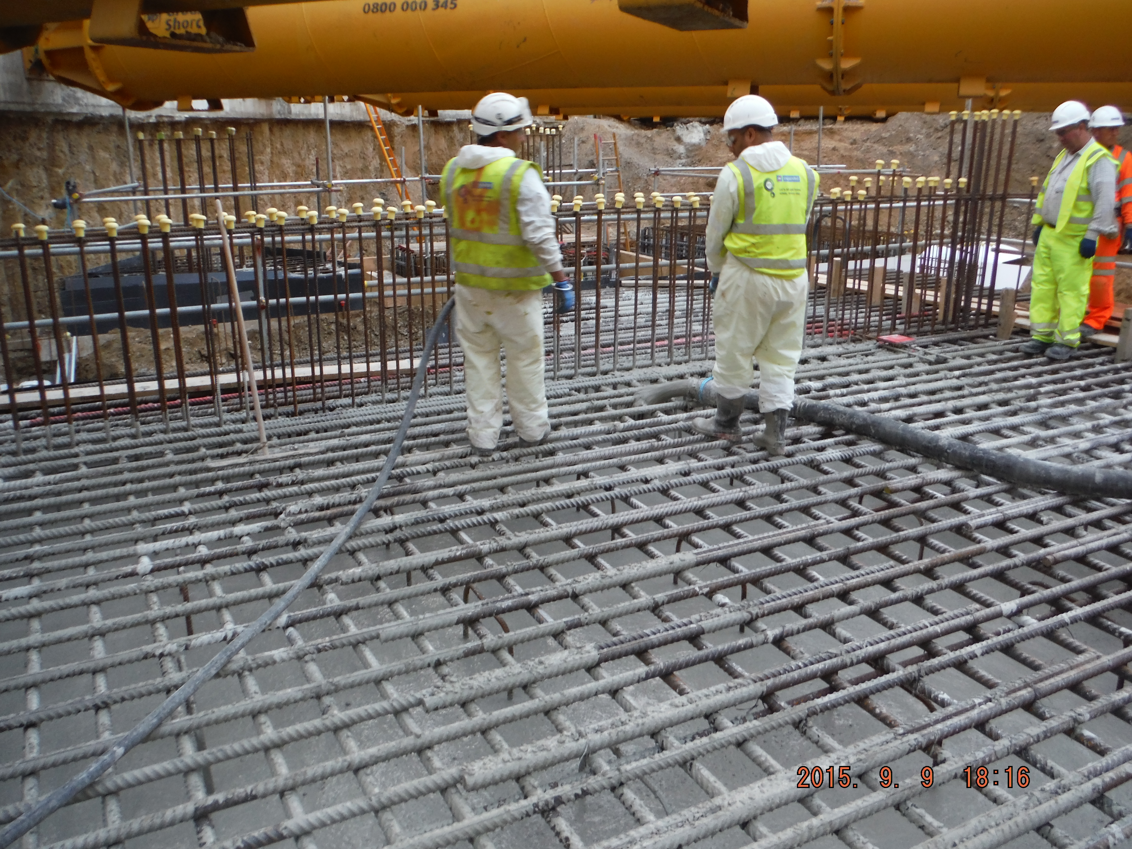
Pour was to underside of slab level, which is about 400mm below the height of the reinforcement shown. Before the concrete is fully cured it will need to be removed from the rebar.
Overview of raft pour – see wall starters to negotiate when curing.
Next day thermal shrinkage cracks. The hope is that when the slab is cast on top it will have fewer cracks because it is only 450mm. Additionally, it will contain a waterproofing additive to prevent water ingress.
Quality Assurance
The quality assurance process involved taking flow tests of the wagons every 5 vehicles and cubes every 50m3. Each delivery was checked for the mix and the details recorded on the pour history sheet (mix, batch times, location of where the concrete ended up). The idea being that should a random concrete wagon arrive at our site we would spot it. Amusingly, one of our wagons ended up somewhere else who were not using quite such a stringent checking process!
There was a drained cavity sump within the pour which had to be in waterproof concrete and so this was poured using a hyrib stop end with the last pour of the day/night.
When we come to do the slab the final finish will be an epoxy floor coating, the concrete slab will be shot blasted to give it grip because it is a car park. Coming to our part in this plan, the slab will need to be cured. There are two common methods:
Polythene and spray on.
Polythene
Advantages: Quick to apply, logistically not too difficult to put in place (polythene rolls are not heavy), 100% moisture barrier (assuming all sides are fastened down),
Disadvantages: Protrusions such as wall starters, polythene marking the slab, mitigated by keeping the polythene sheets as flat as possible, and tearing is likely.
Curing agent
Advantages: Pretty cheap and not difficult to apply.
Disadvantages: It is time consuming to apply, a sprayer is needed, ensuring complete coverage is difficult because it is not easy to see where it is applied. It is not an impermeable membrane so there will be some evaporation.
Recommendations
Polythene, if applied correctly is likely to give a better method of curing because of the 100% moisture barrier. The difficulties in our case of fitting it around wall starter bars can probably be overcome by fastening it either side of the protrusion.
Anyone any experience/views on the matter? What do they do in the US/ Australia for curing slabs?
