Archive
Oz PCH – Ductwork Leakage Pressure Testing.
Introduction
As part of the commissioning of the Air-Handling Units (AHUs) one test is to ensure any air leakage, which results in loss of pressure, is kept to within allowable maximums. This blog briefly discusses a leakage test I witnessed for one of the High-Efficiency Particulate Arrestance/Air (HEPA) filters in the operating theatre department.
In the application of theatres the HEPA filter is part of the laminar flow hood situated directly over an operating table. Here the filter’s minimum resistance (pressure drop) to airflow is specified at around 300 – 400 Pa at 370 l/s flow rate. The effect felt by the patient undergoing an operation is one of a soft blanket of very clean air.
HEPA Filter Function
HEPA is a standard and not a type per se, set by the United States Department of Energy (DOE) and is only awarded to filters that satisfy certain standards of efficiency. To qualify as HEPA an air filter must remove 99.97% of particles that are of 0.3 micrometers (µm) in diameter.
HEPA standard filters are composed of a thin mat of randomly arranged fibres. Fibres are typically between 0.5 to 2.0 µm and made of fiberglass. The air space between fibres is typically > 0.3 µm and the common assumption that fibres smaller in diameter can pass through (like a sieve) is not true. HEPA filters are designed to target much smaller particles which get trapped, by sticking to the fibres, through the following mechanisms:
- Interception. Where particles following a line of flow in the air stream come within one radius of a fibre and adhere to it.
- Impaction. Where larger particles are unable to avoid fibres by following the curving contours of the air stream and are forced to embed in one of them directly; this effect increases with diminishing fibre separation and higher air flow velocity.
- Diffusion. An enhancing mechanism that is a result of the collision with gas molecules by the smallest particles, especially those < 0.1 µm in diameter, which are thereby impeded and delayed in their path through the filter and raises the probability that a particle will be stopped by either of the two mechanisms above; this mechanism becomes dominant at lower air flow velocities.
Figure 1 shows a typical filter layout/construction with pictorial explanation of the three types of filtration; interception, impact and diffusion.
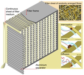
Figure 1. HEPA Filter Layout/Construction.
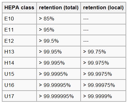
Figure 2. HEPA Filter Classification.
Figure 3 shows the laminar hood above the operating table in the operating theatre.
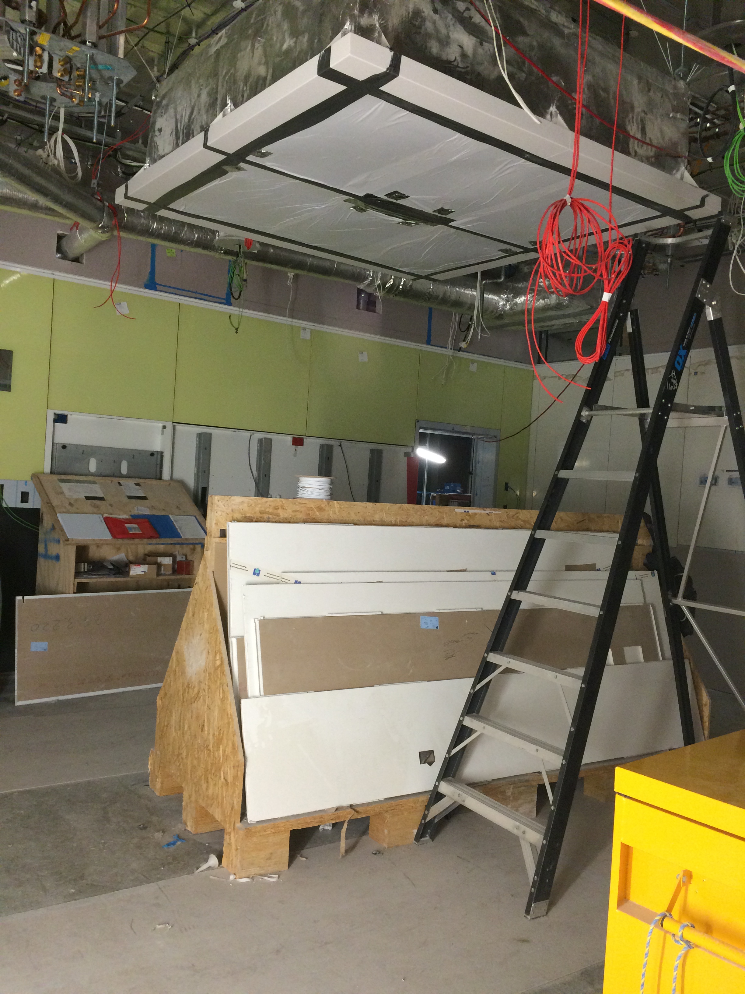
Figure 3. Laminar Flow Hood in Operating Theatre.
Fredon test to AS 4254 – Ductwork for Air-Handling in Buildings, which stipulates:
2.2.4 Air leakage
Duct systems with a capacity of 3000 L/s or greater shall be tested for air leakage at a static pressure of a minimum of 1.25 times the calculated design operating pressure in the tested duct section. Leakage shall not exceed 5% of the design air quantity for the duct system.
The systems in theatres are not greater than 3000 l/s of air so there was no actual requirement to test but Fredon conducted them regardless.
Leakage Test
As per the AS, 1.25 x our design pressure gives just below 750 Pa. The design pressure being the pressure produced by the fan plus any losses created by the Fan Coil Units/filters in the AHU (about 150 – 200 Pa) totalling around 600 Pa. The test achieved this and further more we were assured by Fredon that under normal operating conditions the duct would not reach this pressure.
The ductwork in question was one of four terminals branching off a single AHU (see fig 4). Each terminal has a flow rate of 370 l/s x 4 = 1480 l/s. Testing for a maximum of 5% leakage at a pressure of 750 Pa gives 5% of 1480 l/s = 74 l/s.
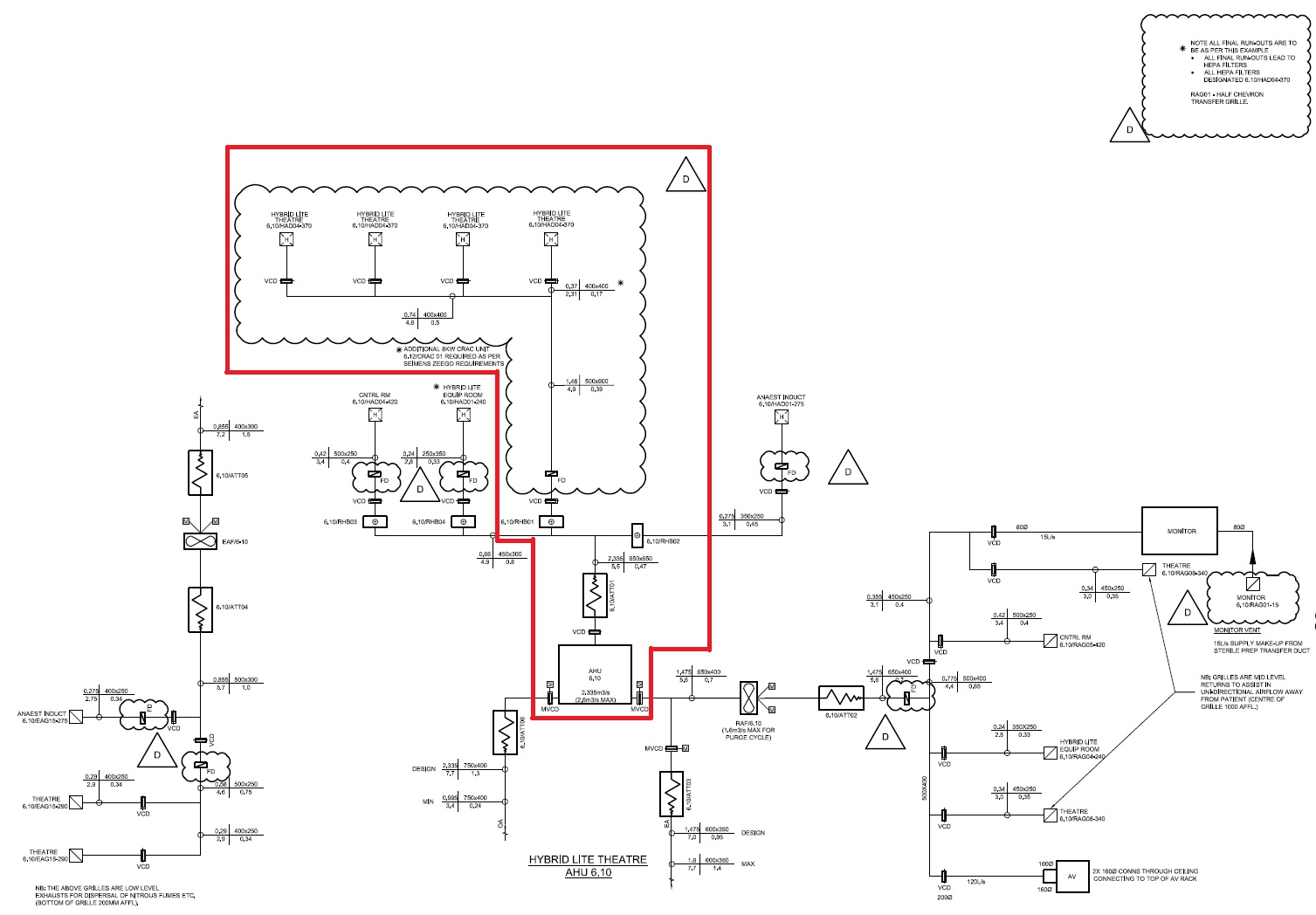
Figure 4. Schematic of AHU 6.10 showing 4 x Theatre Laminar Flow Hoods.

Figure 5. Leakage Test Sealing Plate and Hose.
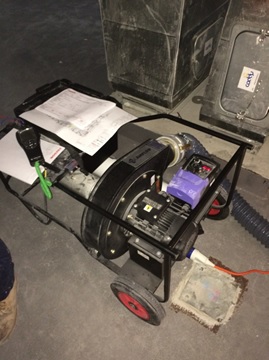
Figure 6. Leakage Test Rig.
Potential Issue
There was a potential issue raised as NDY, design consultant, stipulated in their design specification that ductwork should be tested to CIBSE standards – which refers to Heating and Ventilating Contractors’ Association (HVCA) DW/143 Ductwork Leakage Testing. Here it states that the system leakage loss for Class B medium pressure ductwork, under operating conditions, should not exceed 3% of the operating pressure.
Therefore, 3 % of 1480 l/s = 44.4 l/s.
So, 13 l/s is still well within the CIBSE/HVCA limits.
There was also a further potential issue in that the client may have wanted the test pressure to be the maximum for that class of ductwork, which is 1000 Pa operating pressure. As Fredon were adamant that the system would never operate above 750 Pa they were reluctant to test to this higher pressure.
In order to ascertain if the leakage would still be within the maximum limits due to the increased pressure a calculation could be conducted. There is no precise formula but it is generally accepted that leakage will increase in proportion to pressure to the power of 0.65 (HVCA 2000). This is due to leakage from ductwork occurring at the joints and seams and is therefore proportional to the total surface area of the ductwork in the system.
Therefore:
(1000/750)^0.65 = 1.2056.
1.2056 x 13 l/s = 15.76 l/s (for 1000 Pa). So, 15.76 l/s of 1480 l/s = 1.06% – still well within the 3% limit.
As it turned out the client did not request the 1000 Pa test pressure and so the calculation was not needed but at least it enabled me to investigate the issue.
Remaining Leakage Testing
Once all HEPA filters have been tested, from the plantroom through the slab to the hoods, and passed the ceilings can be closed and then the remaining ductwork from the plantroom slab back to the AHUs can be tested. This approach ensure concurrent activity for other trade contractors and by splitting up the ductwork Fredon can more easily identify and locate if an area of ductwork fails testing.
In Other News
I completed the annual City 2 Surf Marathon at the weekend, my first standalone marathon, in 3hrs 30mins; pretty chuffed and it took till mid-week before I could properly walk, pain-free, up and down stairs!