The Lost Thome
Apologies its been so long since I lost posted, you poor people! I found this post drafted and ready, from before I went on summer leave. I must have neglected to actually put it on the site in the rush to get out of the door.
The Chiller Plant is nearing completion (structurally) and the steel sub contractor building it is starting to prepare for its next large steel erection task on site. Construction of the Chiller plant has been somewhat of a rehearsal for the construction of a large steel truss roof, architecturally designed to be the crown jewel of not just the JOC project but also an icon of the campus. Colloquially known as the ‘Bridge of the Enterprise’ because of its elliptical shape, it will be more of a challenge than the chiller plant. So far it has been high on peoples agenda because of the proximity to an adjacent site which will make de-confliction of crane picks impossible. Cue the start of night work. This is an interesting issue in itself because the adjacent project is c. 1 year behind schedule and so the impossible deconfliction issue is not of our making. In the ‘real world’ I am sure that there would be much less accommodation made for the late contractor and numerous claims for LDs and delays etc. However USACE is required to manage the programme and so the success of both projects must be considered.
We also had to throw the erection plan back to the PC this week. I was part of the team reviewing it and gave general input about compliance to the USACE health and safety manual (EM-385) as well as being the ‘Structural Lead’ for the JOC, whose real Structural Lead was in Hospital with his wife who had broken her fingers playing American Football. The plan seemed OK on the face of it; containing all elements required by EM-385 (the USACE H&S document). These include details of site location, material deliveries, staging and storage, co-ordination with other construction, crane type and capacity, lifting methods, pick path, site preparation descriptions, stability of the erection, certifications …etc. The main bit of concern to me was the actual description of the steel erection activities. Fairly key then.
The subbie had done a brilliant job of communicating the first stages of the job on a simple on pager with different colours corresponding to different stages of the phase. It highlighted what the safe ‘walk away’ point was, was easy to read and clear (PSB)
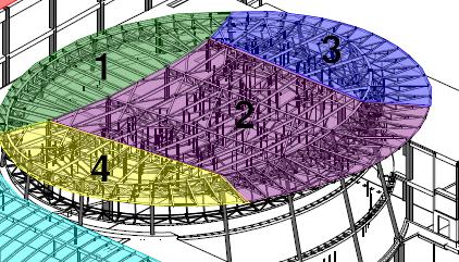
Colour Coded – showing sequences
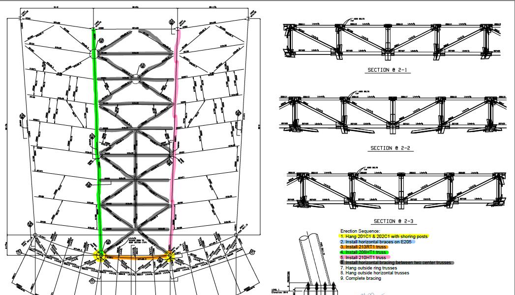
One of the sequences in detail
Unfortunately –
that’s where it stopped. I looked to the narrative for help, but it kept referencing other pages of the document, which was not paginated. It left me filling in the next stages based on assumptions and wooly assertions based on my knowledge of the project and a narrative that said ‘repeat steps 3 – 7’. To my mind totally inadequate. The erection plan itself should be a simple document that you could give to pretty much anybody who should then be able to look through and clearly identify at what stage the construction is at, what’s coming next and at what stage it is safe to terminate construction such that what’s already been built won’t fall down. If the subbie had simply done away with the narrative and continued with ten one-pagers I think the plan would have been much better.
So what’s the point of this bit of the post? 2 things: In the army we are gently encouraged to communicate on paper in set formats. This helps, and it’s a skill/requirement we perhaps take for granted. We can add a lot of value to a site / task / project through non-technical skills like these. But secondly the most complex of tasks can be communicated through the use of some simple, well thought out sketches. In this case, it would have been a lot better to have done so.

Brad – I very much concur with your assessment of the erection plan not being sufficient. Recently I have seen a couple of extremes in plans production. One was a tower crane erection plan which detailed an hour by hour method of the task. The erection involves a 250t mobile crane to erect the tower crane, a public road closure, consideration of the Ministry of Sound (our next door neighbour) and Southwark council for working outside of allowed hours (over full weekend). Albeit a pretty simple task, the detailed, visual plan won immediate favour with the council and I am sure will help get the out of hours permission we need. On a different scale was a task brief for the construction of a 3.5m deep lift pit produced by us. It is a pretty dangerous task because of the excavation depth, close proximity to other labour gangs and constrained nature of the site but has not really received much attention to date. The task sheet lacked understanding of how the task was to be completed. Although I thought I would never say this, a simple set of sketches for the construction sequence actually helped produce a sensible and safe plan, now to be put to the test!
I agree with you in that pre-defined templates can help guide a method statement in terms of sensible sections, and that sketches are a useful tool to communicate risks and mitigation measures. Not sure I agree with the non-technical skills bit, because for me to build something needs engineering understanding. For the problem you present, what headings would you suggest for the erection plan? I imagine it would involve a significant temporary works piece and so would be useful to understand how you bring that into a generic format?
Hi Damo – its good that you’ve been able to see both ends of the spectrum. As it turns out there was confusion between the PC, Subbie and Fabricator as to what the plan was so the erection plan had no chance! I think you might have got the wrong end of the proverbial, or I have miscommunicated; I meant that the non-technical skill of putting thoughts (in this case instructions) onto paper in a concise, structured manner is one which pays dividends. I think that we, in the army, are quite good at it given that we are encouraged to use JSP101 and work is red penned as a matter of course, usually by 2 or more people. In any case, something as simple as referencing page numbers in a non-paginated document, for example, would not pass scrutiny, nor should it. That is what I was trying to convey about non-technical skills being useful. ( I certainly wasn’t suggesting that a technical subject should be tackled by someone with a lack of engineering understanding!)
As for the generic format, most of the titles that are required are in the original post (site location, material deliveries, staging and storage, co-ordination with other construction, crane type and capacity, lifting methods, pick path, site preparation descriptions, stability of the erection, certifications… ) Perhaps a useful way to communicate all these different elements would have been a simple main document with lots of annexes (I’m sure Guz will agree!)
Hope you are well
A picture paints a thousand words and the physical act of drawing out how you are going to build something will highlight and force consideration of the key risks.
Brad,
I concur that keeping things as simple as possible and using drawings and sketches where practicable to aid in getting the point across massively helps.
On a slightly different tangent, but still linked to using old school methods, I am in the process of writing a blog where printing off A0 sized drawings and highlighting in different colours to show progress and understanding had proved invaluable; blog to follow soon.
Hey Fran, Definately a fan. I resorted to printing out a 1:1 scale model to represent a 1T base plate that wouldn’t fit as per the design drawings. We overlayed it on top of the rebar and with a bit of jiggery-pokery were able to come up with a solution; its being installed this morning. If it looks stupid but it works, it ain’t stupid!