Archive
Oz PCH – Helicopter Noise Attenuation.
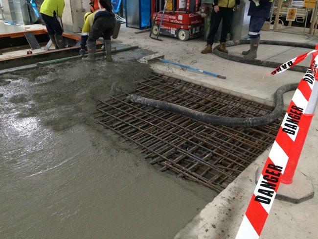
This pic is to entice the civils to read my blog…more on this at the end.
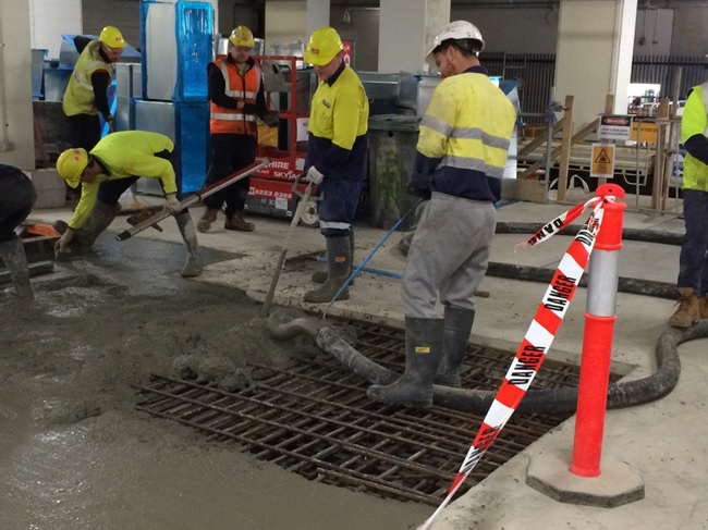
Fig 1. Concrete Pour in the Basement.
Introduction
This blog aims to discuss the potential issue of helicopter noise being carried throughout the building using the ductwork as a noise passage/channel. It also covers the attenuation used for the back-up diesel generators.
Problem
The helicopter pad was procured as a packaged unit but there seems to be a scope gap for ownership with its commissioning. That aside, the acoustic consultant for JHG stated a helicopter using the HLS (red line in fig 2) passes directly over AHUs housed in two non-acoustic out-houses (yellow line in fig 2) and produces noise levels of around 105 dB(A) as a point source. The (A) refers to the A-weighted sound pressure level which approximates the human ear’s sensitivity to sounds of different frequencies. Without this filtering, calculated and measured sound levels would include sounds that the human ear cannot hear, such as dog whistles (high frequency) and sounds made by large buildings with changes in temperature and wind (low frequency).
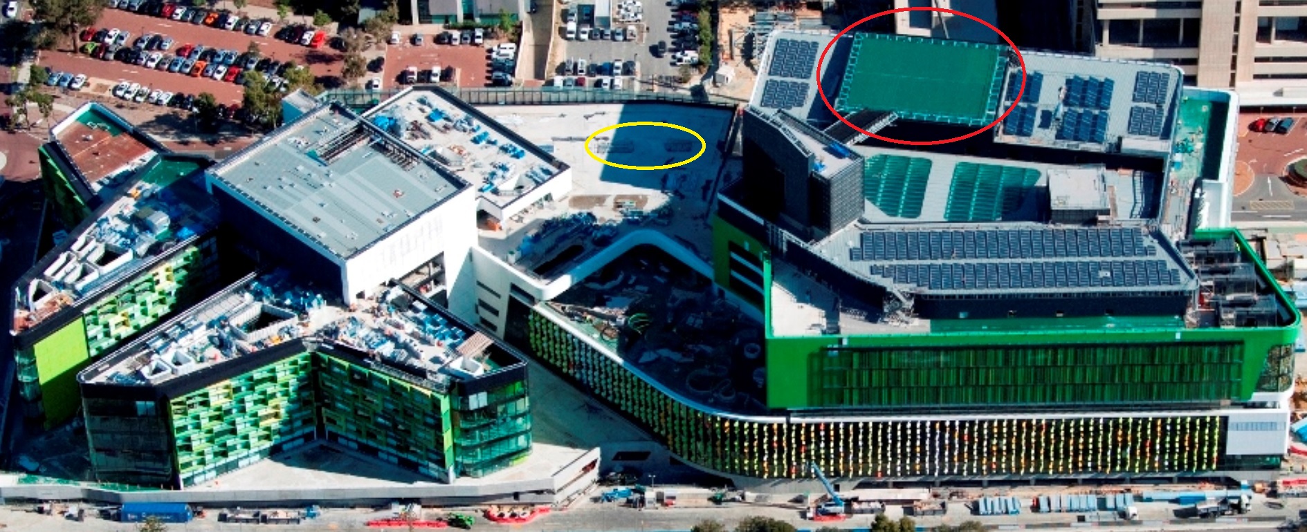
Fig 2. Aerial View – HLS (red line) AHU Out-houses (yellow line).
For comparison table 1 indicates where 105 dB(A) sits amongst other familiar sounds.
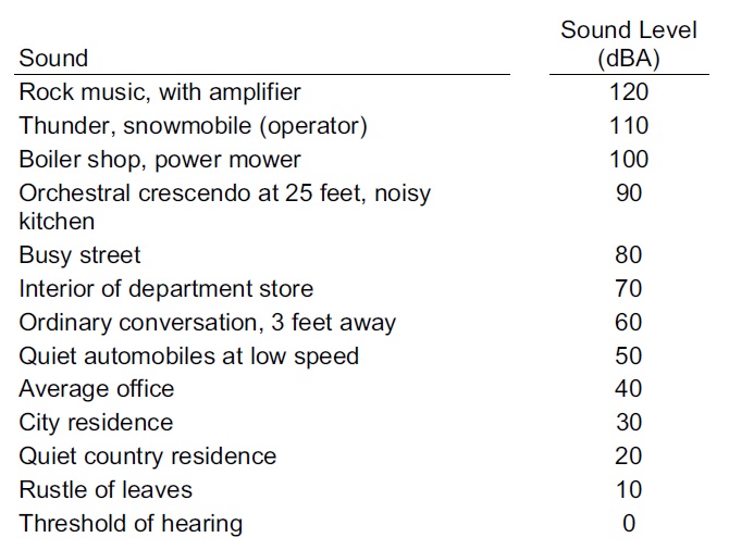
Table 1. Common Sounds on the A-Weighted Decibel Scale.
These particular AHUs, supplying conditioned air to the Theatre Department, have been placed outside on top of the plantroom as they wouldn’t fit inside due to layout design changes. This places them in close proximity to the rooftop HLS and are only covered, for weather protection reasons, by a non-acoustic out-house structure. Fredon, who are the plantroom mechanical fit-out subcontractors, have stated that there may be an issue with sound levels in the Theatres and that they have to conduct an assessment of the noise levels produced by a visiting helicopter to determine how much sound will travel down the air-conditioning ductwork and if they comply with the performance standard at the outlet grills.
So What?
Fredon were aware they had to conduct their own acoustic performance tests, highlighted at tender, as they knew a HLS was a design package; the situation now becoming more problematic with the re-location of the AHUs outside of the plantroom. Fredon should have factored-in the acoustic performance testing when the re-design took place instead of leaving it till now, once the ductwork installation is complete.
Solution and Possible Implications
They now need to conduct the acoustic performance test and if they don’t comply they will have to fit attenuators into the ductwork in order to reduce noise travel, commercially this will be at Fredon’s expense but could potentially hold-up commissioning and may incur delay claims from JHG. The impact could be reduced if they can fit attenuators in the plantroom directly below the AHUs on top and this would cause the least pain in terms of cost and time delays but it will depend on how much attenuation is required and how congested the plantroom is already; the alternative being to fit them further downstream in ceiling voids, that are already closed up, but this is something we and Fredon would want to avoid if at all possible.
Fredon are waiting for confirmation of the noise criteria from the design consultants NDY before continuing with the test. NDY are waiting for the client to sign-off a design departure for the criteria laid out in table 2 (red box).
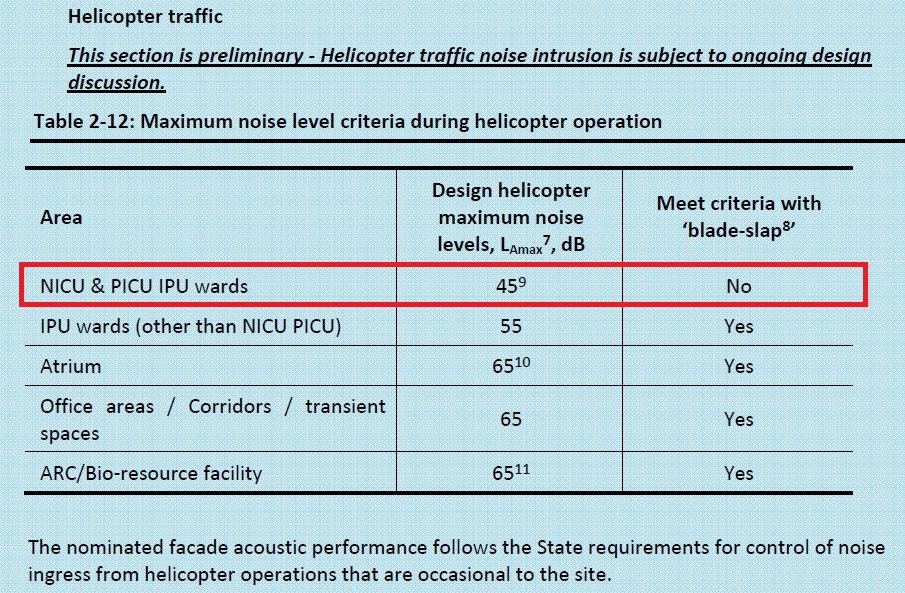
Table 2. Max Noise Level Criteria during Helicopter Operation.
NB:
7 Typical values generated by helicopter movements along defined flight paths.
8 ‘Blade Slap’ is the sharp cracking sound from helicopters, typically occurring with turns, shallow descents and flare approaching a hover.
Performance criteria are provided in Table 1 on the basis of data and modelling obtained with blade slap characteristics included.
9 Assessed in terms of the continuous equivalent LAeq level. To comply with 45dB LAeq(15 mins), the LAmax (slow) is to be less than 55 dB(A) or it can exceed LAmax (slow) 55 dB(A) for 6 minutes per hour. Further LAmax should not exceed 65 dB(A) at any time.
How Attenuators Work (Simplistically)
In simplistic terms, when fitting an attenuator in line with ductwork it requires a larger space than just the original ductwork. Fig 3 shows this including the tapered sections either side of the attenuator.
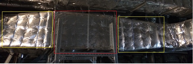
Fig 3. Attenuator. Red box showing the attenuation section with the two yellow boxes showing the tapered sections.
Theoretically and in practice an attenuator works by the noise being absorbed by the acoustic filler (wool mixture) in the solid sections with gaps between to continue to allow air flow. Due to the sections taking up space (around 40%) of the duct volume, the air velocity increases. This increased velocity creates its own noise termed ‘regenerated noise’. As long as the net noise level has reduced it is considered worth doing but engineers can get caught in the trap of the law of diminishing returns due to the increased pressure losses caused by the reduction in volume. This is caused by a pressure change/differential between the point before and after the attenuator. This results in second and third order effects of requiring a higher fan speed to overcome the pressure losses and then requiring a bigger fan motor which uses more electricity. A way to resolve this is by maintaining the pressure over the attenuator which can be achieved by ensuring the attenuator is the same volume as the ductwork leading up to it. Due to the space taken up by the acoustic filler sections inside the attenuator, means that the overall dimensions of the attenuation section has to increase, as shown in fig 3. Sometimes this causes issues if there is limited space in a ceiling void.
A Different Example – Diesel Generator Noise Attenuation
I had a look around one of the 3 x 1.25 MVA back-up diesel generators to investigate its noise attenuation design.
The generators, manufactured by Cummins, are housed in individual acoustic and weather protected containers.
Inside the container, at both ends, are the attenuation sections as shown in fig 4. These are vertical sections (red line) with a permeable membrane filled with acoustic noise damping wool. At this end outside fresh air is being drawn in (blue arrows) by the generator radiator fan but the noise is escaping (yellow lines) through the gaps between the acoustic sections.
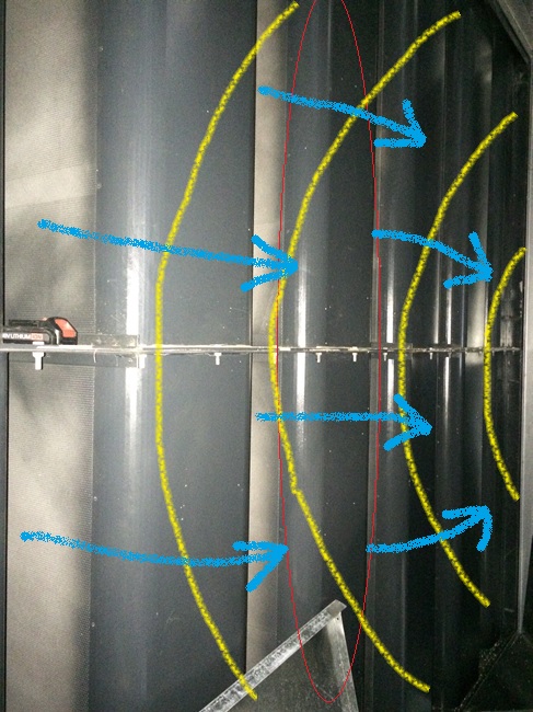
Fig 4. Generator Attenuator Section – Radiator Fan End.
Fig 5 shows the incoming outside air (blue arrows) and the noise path (yellow lines) taken as it bounces between the two acoustic sections losing noise as it passes through the acoustic material and finally out the louvres at the end.
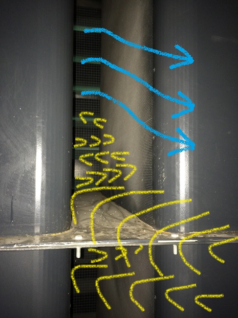
Fig 5. Generator Attenuator Section Working – Radiator Fan End.
The capping louvers at the container end have acoustic foam attached to the underside of each horizontal louver and so also acts to reduce noise coming out (yellow lines in fig 6) but allows fresh air to be drawn in (blue arrows).
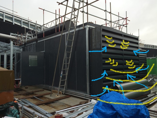
Fig 6. Generator Louvre End Capping.
We are currently waiting for the generators to be run-up and tested with the installed fuel supply system and for all three to be tested for load sharing as part of system commissioning. Until that time we cannot fully test the acoustic noise levels produced.
Useful References
BSRIA – A Guide to HVAC Building Services Calculations (2007) (second edition) p.125 – 133, describes the acoustic calculations required in design, in particular ductwork noise transmittance.
CIBSE Guide B – Heating, Ventilating, Air Conditioning and Refrigeration (2005) – Section 5 Noise and Vibration Control for HVAC p. 5-1 to 5-22.
In Other News
For the civils, the below pics are from the final basement concrete pour filling the ground slab where one of the tower cranes once stood. Fill your boots to ask questions but I most likely won’t know the answers…I just took the pictures!
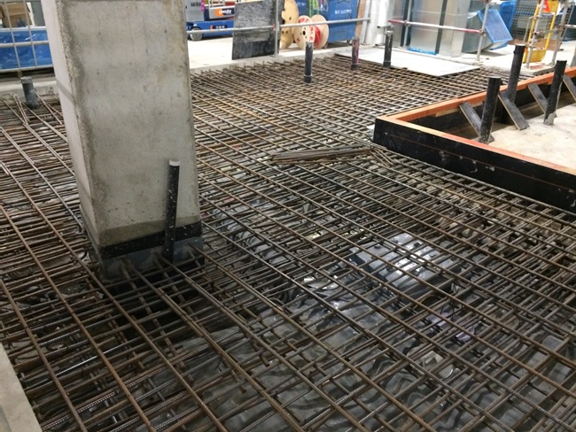
Rebar, Form Work and Tower Crane Bearing Pile
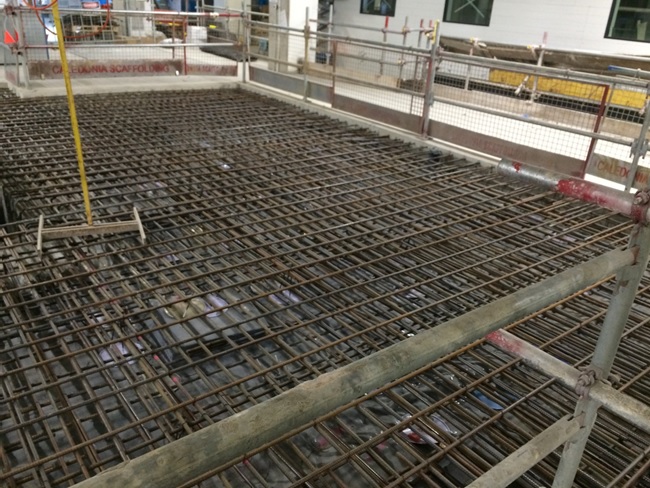
Rebar and Tower Crane Bearing Pile
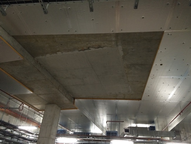
Previous above Slab Aperture for Tower Crane
Concrete Pour

Finished Pour Levelled
And finally…speechless!