Site Two Fifty One – Drainage testing and Assessment of plunging reinforcement in piles
Site Two Fifty One – Drainage testing and Assessment of plunging reinforcement in piles
Drainage testing
As I mentioned before the underslab drainage needed testing before the concrete slab was cast. The method for this was actually very simple. There are 2 common options: air and water tests. We have done air tests. The method is to bung the openings in a run (such as gullies, rodding eye, down pipes, etc) pressurise one end with a pump to 100mm on a U tube Manometer. Over a 5 minute period the drop should be no more than 25mm. If this is the case move on to the next run, if not, test shorter sections until the leakage point is found.
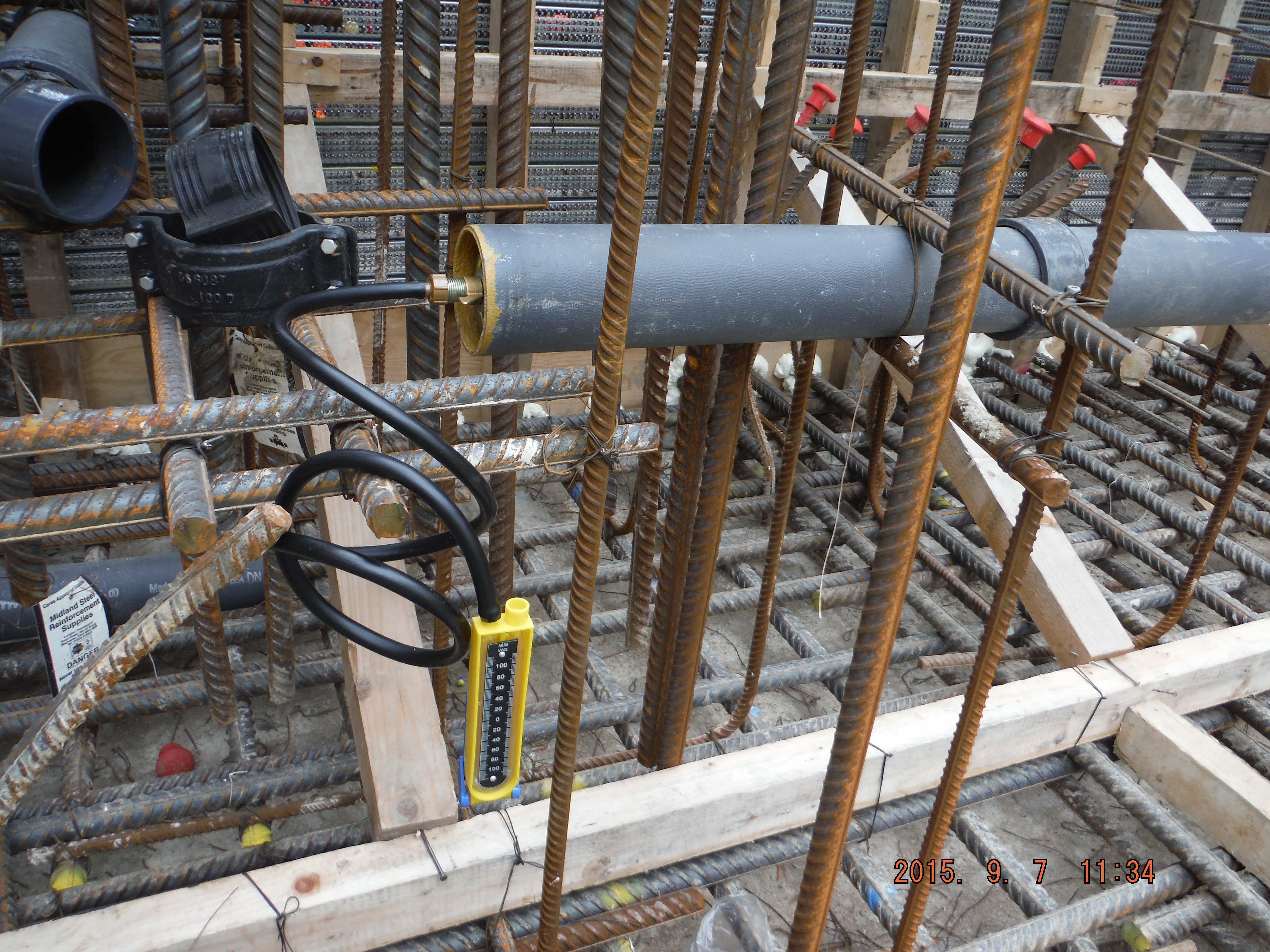
Manometer used to confirm pipes do not leak.
Tension
How to get tension anchorage. We have installed our first tower crane base this week. The 80m3 pour is impressive, not least because of the 0mm tolerance on the crane base but more because of the W bars used to provide tension reinforcement within the pile cap.
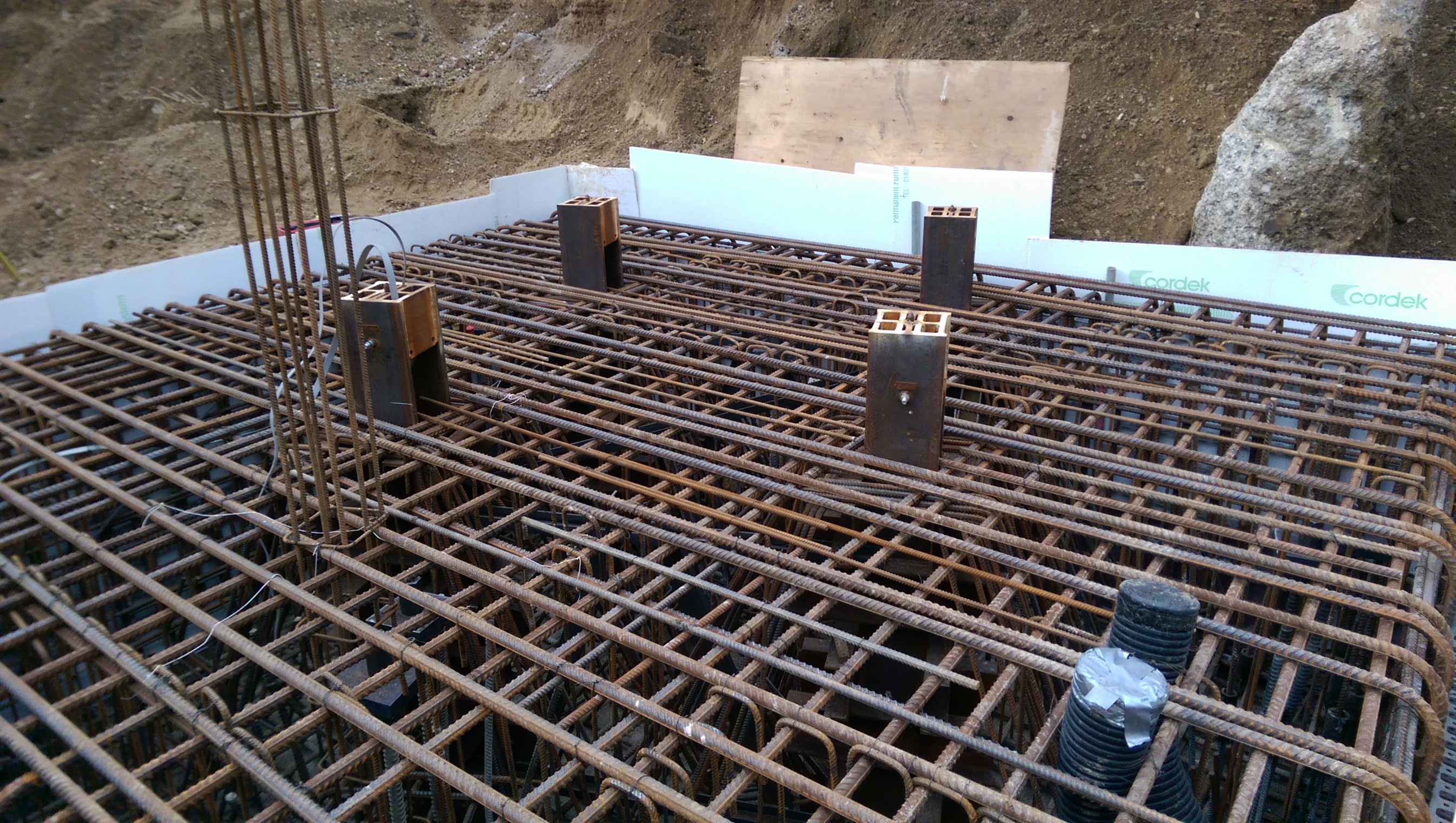
If you open this image up and look at the 4 tower crane legs you can see the “W” reinforcement.
The other interesting point is that dywidag bars the length of the piles (about 26m) have been installed to avoid the whole pile cap rotating. However the anchorage length required is greater than the height of the pile cap. To solve this, large (676cm2) plates and nuts have been used to give greater anchorage. Has anyone else seen this method used?
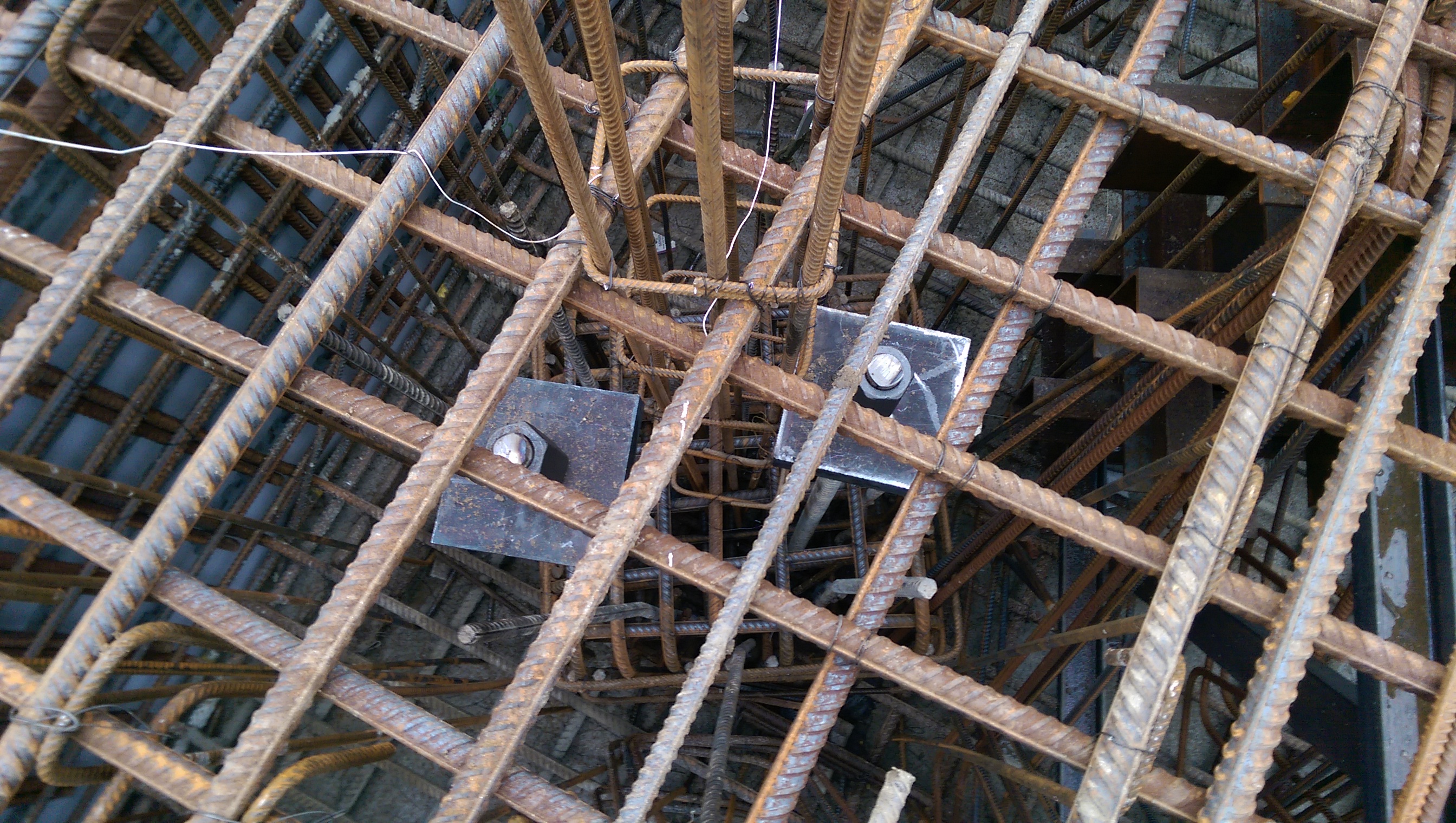
Square plates used to provide additional anchorage.
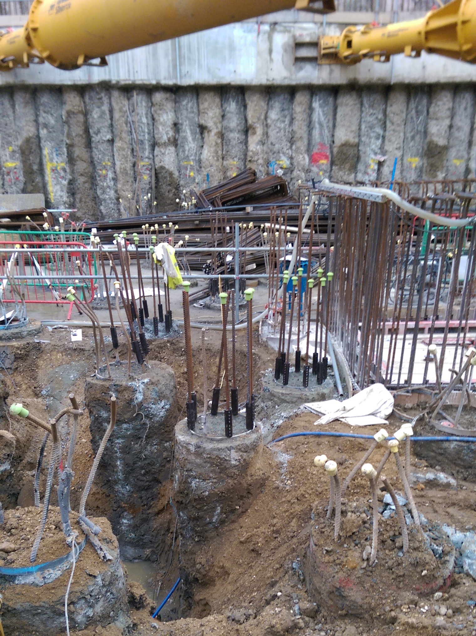
Piling methods
The piling method at Two Fifty One was to install piles at ground level, plunge the pile reinforcement and then excavate ground to formation level (approximately 5m lower), breaking the piles are we go.
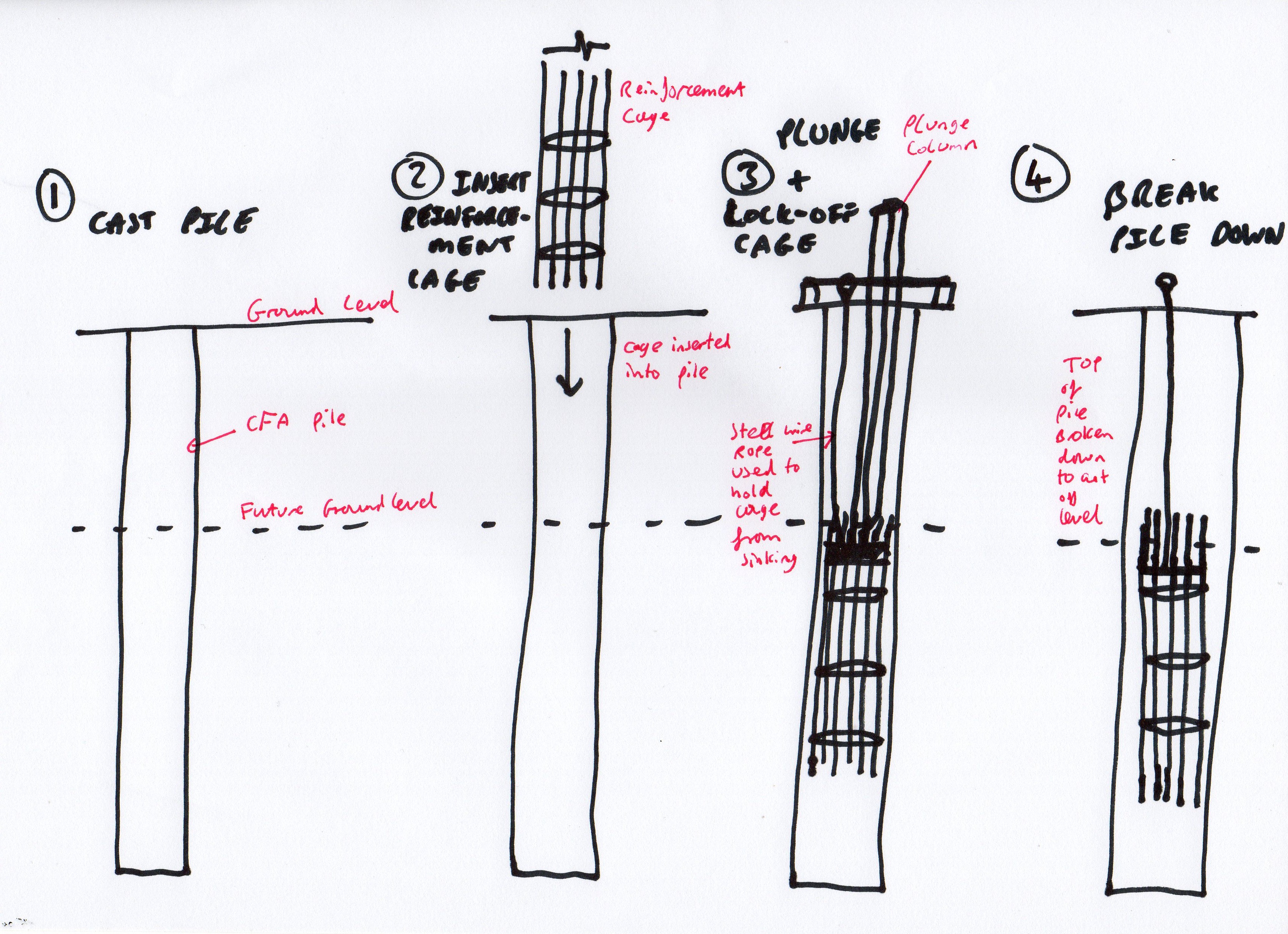
2-Year old’s impression of plunging pile reinforcement cages
This has a significant disadvantage. Let’s assume 300 piles, 5m waste, 0.75m diameter, £140 per m3 of concrete equals a little under £100k in waste concrete, plus time to break piles, plus muck away time.
However the advantage is that the piles can actually be installed. If the site was deeper the props would be in the way of the piling rig and getting the rig out of the site would have been pretty tricky. Bearing in mind the piling package was about £4M, this represents a 2.5% fraction of the cost.
Further issues. Submerging pile reinforcement cages to an exact cut-off level means it was not done very well. Mostly are within tolerance for anchorage requirements but some are too low.
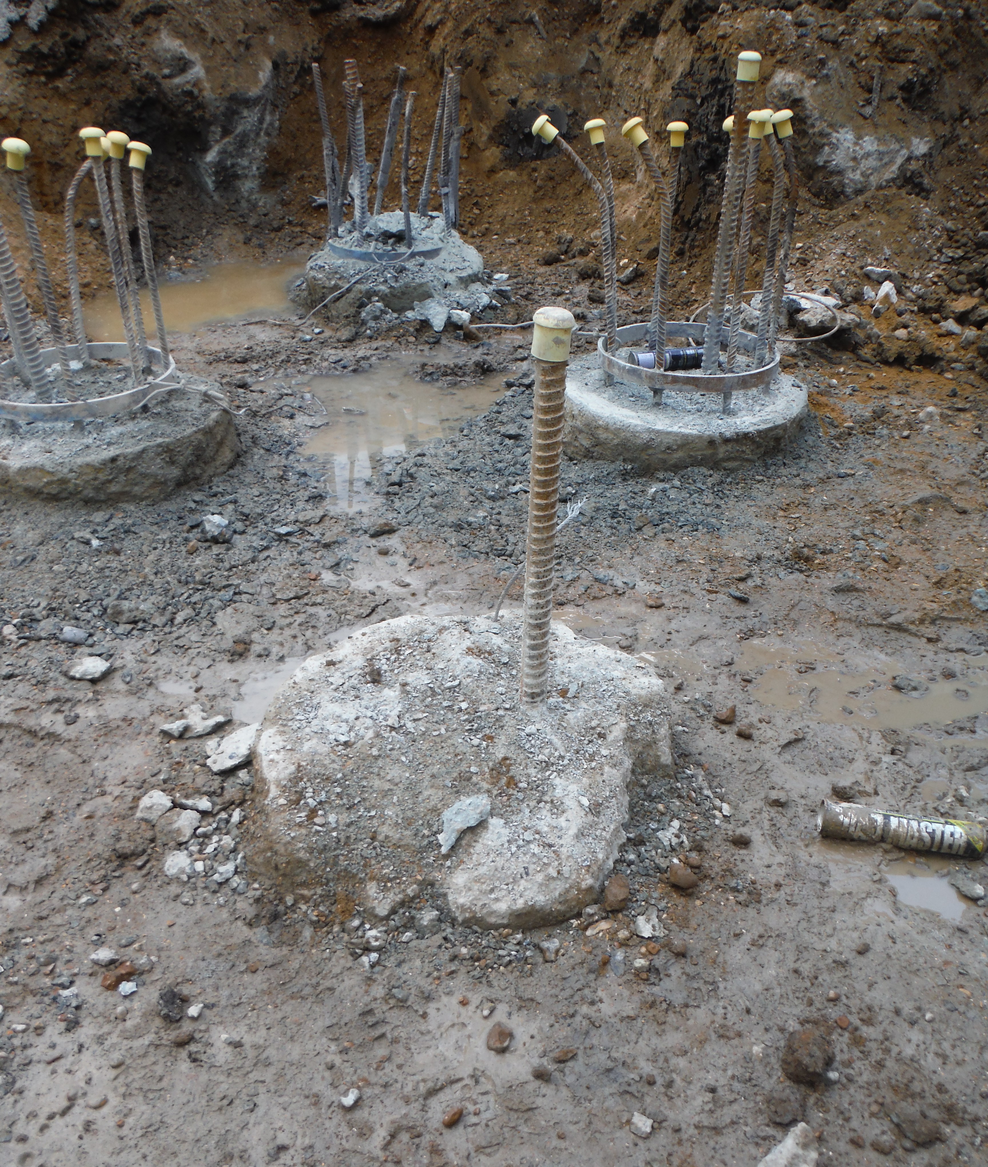
Spot the difference – something is not right about this pile…
Moreover, in order to dig deeper pits we have had to cut some reinforcement down (to facilitate excavator arm length reaching to dig level). Therefore to extend the reinforcement back to the correct length couplers have been used. Bar diameter dictates coupler size. The common MPT couplers seem to be what everyone has heard of, they are British Board of Agreement approved, but unfortunately not Certification Authority for Reinforcing Steels (CARES) approved. Laing O’Rourke only allow CARES suppliers – due to adhering to certain quality standards and also as a wider corporate image piece. Therefore once this hurdle was overcome, the couplers were installed. As a final point the locking bolts should shear off to demonstrate correct installation.
Couplers used to extend pile reinforcement.

Damo,
In your drainage air test what’s the starting air pressure?
Apart from seeing the manometer level drop do you have any other QC check on the pipe joins during the test?
Not the same application but we had a stainless steel RO pipework leak post pressure testing. The issue was the crimped coupler was crimped correctly (leaving the crimping mark on the outside of the pipe) but the joining pipe wasn’t seated all the way in and didn’t butt up against the collar seal. This meant it held long enough to pass the static water pressure test but later began to leak.
Clearly your drainage pipes will be encased in concrete once poured but do you use any type of outer sealant at the couplers?
If a pipe did leak what kind of damage to the surrounding concrete would that cause?
Hopefully not an issue on your site but an old trick with testing is to fit bungs to all ends and then reach up and fit one inside the test end so that you test nothing at all! If pressure is up when the inspector arrives and the operative is ‘just putting the last couple of pumps in’ to get to 100mm there is a magical nil head loss. Two alarm bells are 1 not seeing it pressurised from zero with an opportunity to look inside the pipe and2 a zero or very minimal pressure drop which is too good to be true…
I have advised JM to make use of the illustration of pile reinforcement in his forthcoming instruction. The use of couplers is pretty common now. The need is to k a) know that the bolts have been torqued off, and b) note that they still protrude sufficiently to indicate that they have been tightened against a bar i.e. that the bar is fully inserted unlike Fran’s crimped pipework…
I notice that you are breaking down and not croping. Has this been discussed?
Fran – thanks for the comments. Not sure on the pressure but it is created with a small hand pump (I am sure you have something similar fitted to your bike), so I suspect low. Where we have some rising pieces we have used a silicone seal between the screw thread. You are right in that the pipes are cast in concrete. Between pours (joints) rocker pipes are used which is effectively to allow some movement to prevent cracking. The pipes are also hung using reinforcement from the rest of the reinforcement cage which provides rigidity during the concrete pour, with the aim being to avoid damage during the pour. However, should the pipes crack in the future I would think the cover to the nearest steel must be at least 50mm which effectively should be sufficient for a 60 year plus design life. In terms of protecting the structure, every drainage protrusion has waterproofing hydrophilic strip around it so the likelihood of water rising upwards is reduced.
Richard – thanks for your comments too. No issues with the bungs, these are being done correctly because we (site engineers/myself) are doing the quality control and additionally building control conduct inspections and would soon lose faith if we were cheating!
Pile cropping is a good question. The photo shows the large yellow props about 3.5m above the piles which effectively mean we cannot fit an excavator which could hold the cropper on below them. We actually hired a Cropper in at about £1000 per week until we realised the smallest excavator it would fit on was too tall for the props. We are close to the props with small 5t machines so the idea of using the Cropper is a good one but defeated with site realities.
Pile breaking using a hydraulic breaker is working fine but demands decent operator level to 1. Avoid snagging the hydraulic hoses against the rebar and 2. To avoid totally mangling the reinforcement. The noise is loud (above 85dB), which means everyone has to wear ear defence but the additional concrete removed from the centre of the pile (which a cropper may not get to without totally destroying reinforcement) means there is less breaking of the piles by hand required. Cost wise, I think the weekly cost of an excavator is less than the weekly cost of a pile cropper – they can also do much more!
100mm head of water in a manometer = 1 decimeter = 1 litre over a 100mm square = 1 kg i.e. 100kg per square metre i.e. 1000N/m^2 i.e. a 1kPa presure unless my maffs is wrong.
That’s 0.01 bar. To put into perspective my road bicycle tires are inflated to around 100 PSI = 6.9 bar so, 0.01 bar is a pretty low pressure. Unless Richard’s maths is wrong…
Of course if you’re using a portable mercury manometer that would be nearer to 13.3kPa or about 2 PSI