Archive
GRP Pipe Design
Design
The remainder of the GRP pipe line was installed by York Civil, using GRP with flexible coupling free issued by John Holland. The design showed that the pipeline would transition from a flexible pipe (i.e. the use of couplers and concrete thrust blocks) to a rigid pipe (i.e. fully welded) at the interface between GO scope of works. Originally GO were to supply all of their own GRP for the reminder of the underground and the above ground piping that leads to the pumps. However our procurement spotted a potential opportunity and decided to use the surplus GRP we had onsite to free issue to GO instead. This all happened during the tender stage, about three months ago.
Flexible GRP Pipe Installation.
Above Ground Rigid Pipe
Issue 1
After arriving on site GO began some other packages of work and provided spool drawings for the GRP they were supplying for approval. During the design of this GRP the manufactures passed the design to a consultant for ratification. The consultant identified significant issues with the longitudinal strength of the pipe, which had been designed using the specification supplied by our designers (KBR). After this several discussions ensued on site between myself and GO, it became apparent that we had become messengers between the two technical experts (one in KBR and the other in the consultants) who had differing opinions. Eventually I was able to arrange for them to get in the same room and thrash the problem out. The final outcome was that the pipe needed to be upgrade at a cost of $45,000 to deal with the additional longitudinal strength. These longitudinal forces were due to the operation of the pumps and thermal expansion. KBR were able to argue the fact that there was enough information on the drawings for subcontractor to know this and even though GO were on a supply and install contract they had a duty to do some design. Luckily in the same meeting KBR were able to muddy the waters to such an extent over who was responsible for these changes that GO accepted the cost, rather than try and challenge it.
Issue 2
About a week after the above issue was resolved I received a separate email from KBR asking that I check the GRP we were free issuing to GO as there may also be issues with that. After speaking to the GRP supplier it became clear that the pipe would not be suitable for the current design. The design was then changed to switch the section of pipeline back to a flexible. With John Holland receiving a bill for the redesign and a $20,000 variation from GO, with further changes to the design expected this will rise. My role on site has been to manage this process and try to ensure design changes have minimal impact on the work already completed. The cause of this issue could easily be passed back to the procurement team for not checking the pipe would be suitable, however I think it goes deeper than that. The designers were aware of the plan to use the GRP but didn’t comment until GO raised the issue above. In addition the suppliers of the pipe had previously agreed it would be suitable without actually understanding the full design. Unfortunately it looks like cost of all these variations is likely to come to John Holland. Although I have already been tasked with trying to pin this on the designers.
Issue 3
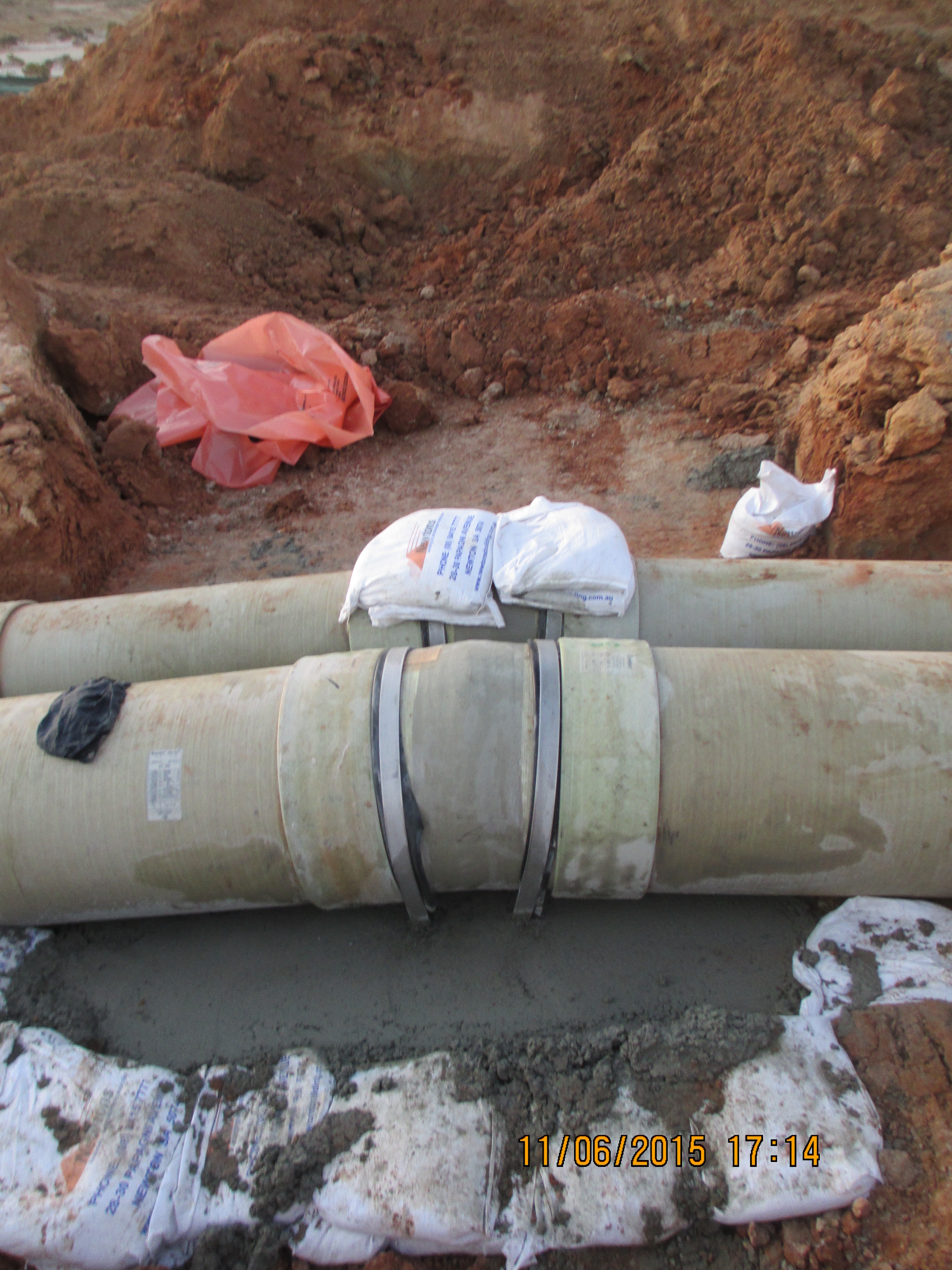
The more worrying issue was the fact that the same free issued GRP was used at the other end of the pipeline where it discharges into the lagoon. The pipe was wrapped to make it rigid, as shown on the drawing and using the wrapping methodology provided by the pipe supplier. Once installed the pipe was hydrostatically tested to 625kPa, a value given by the designers in answer to an RFI just a week earlier. Two days after conducting the test we received a further email from KBR requesting that we not test the pipe as it would fail under the pressure. Luckily the test went fine but the potential for injury was there and as such this has been raised as an incident within the John Holland system. Operationally the designers see no issues with the pipe as it currently is. The pipe is positioned 5km away from the pumps and is open ended so the pressure is deemed to be negligible.

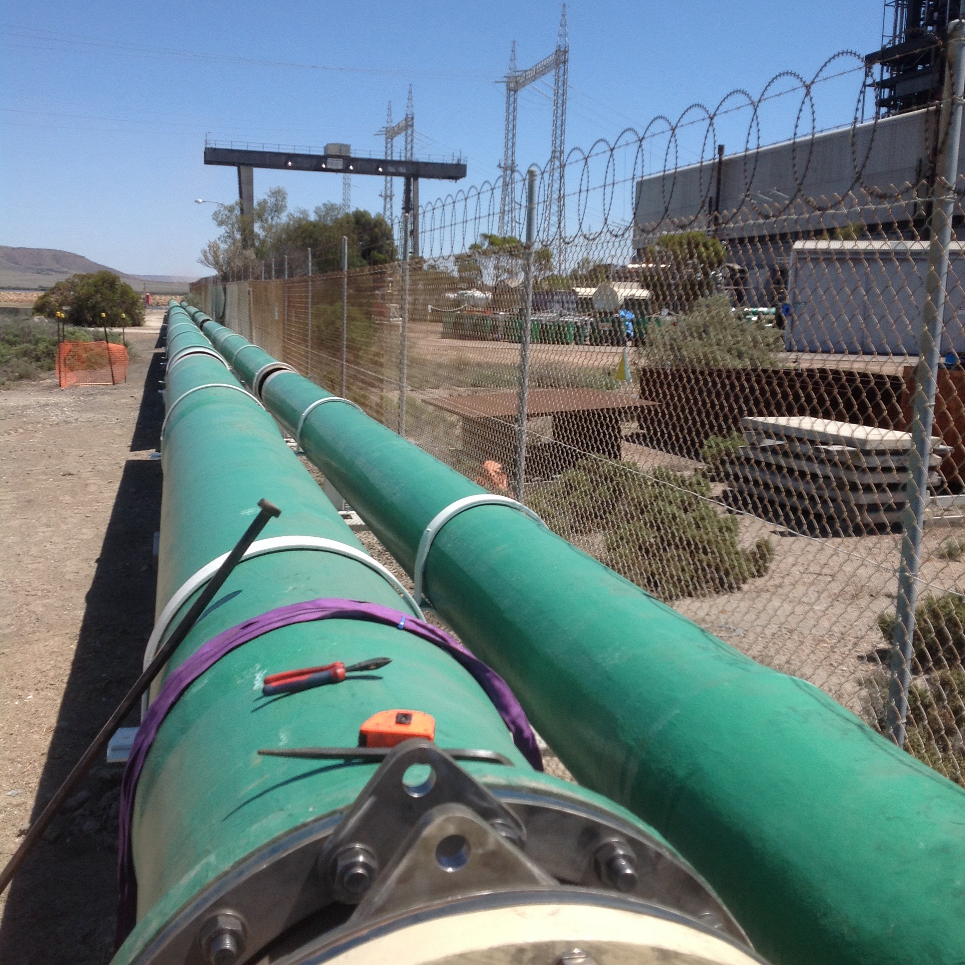
Seawater Inlet Pipe
Conclusions
The design of GRP for pipelines is a specialist area in its own right. In the case of the site at Sundrop Farm it was clear that the designers at KBR were not fully aware of what they were doing in relation to the GRP design. The design and associated documents had a number of flaws which had they been scrutinised by a specialist would have been picked up much earlier, which in turn would have reduced the financial impact of the changes we are now having to manage on site.
With regards to procuring items the supplier needs to know as much information about the environment, system and operating conditions their component will operate in. Had the GRP suppliers understood the full system and operating conditions of this design they would have been able to provide more suitable product capable of operating as designed and reducing the impact of future changes. Instead they were responding to isolated RFI’s from the procurement team, thus providing answers which were not relevant to the situation.
From a site point of view it is difficult to see how we could have responded differently. We were provided with IFC drawings from the designers and pipe procured by our procurement team. The designs go through a review process both by the designers and John Holland. Had it not been for the subcontractor conducting a review of the GRP and us responding to the information they provided the installation would have continued as per the design. The impact of this is hard to quantify, the plant could have operated as designed for years or the GRP could have failed as soon as the plant was switched on.
In other news
I took a long weekend off earlier this month and took the opportunity to drive up to Uluru or Ayers Rock. The drive takes about 12 hours through the outback and is broken up with nothing apart from a missile testing range, the odd service station and Coober Pedy. To break up the journey we stopped at all of these and spent the night at Coober Pedy. The town’s main claim to fame was the discovery of opals in 1915. Troops returning from the First World War began to settle in the area from this date. Because of the harsh climatic conditions the settlers began to tunnel into the rock and build homes (called dug outs) underground.

Wilfred Pointing to His Christmas Present
Today the town has a population of almost 1700 and most of the towns building remain underground. The hotel we stayed in the temperature remained between 22 and 25 degrees all year round without the need for air conditioning, despite outside temperatures exceeding 40 degrees for much of the year. Natural ventilation is provided by a number of shafts that extend from each of room to the surface above. Each room had an umbrella positioned upside down under the shaft in the corner to catch dust landing on the floor. The wiring throughout the hotel was done by drilling horizontally, then using a vacuum to suck a piece of tissue with a piece of cotton attached and then pulling the cables through.
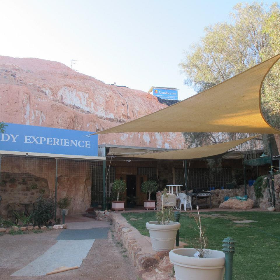
The Comfort Hotel Coober Pedy

Hospital Pass
Part of the role of USACE, as the client’s representative, is to conduct design reviews for design-bid-build contracts (read traditional contracts). These are done at 35, 65 and 95% with comments provided back to the project manager and design team, be it in house or a consultant, through an online system (Dr Checks). The designs are reviewed by us at construction division as well as the design division and are passed out to the clients and facilities managers, probably amongst others.
A couple of weeks ago, due to staff being on leave, I was given one of these to look at the pumps, seemingly alone. Having no idea what to do I browsed the drawings to work out what the issues might be. The project is a new 750,000 U.S. gallon water tower for domestic water and as a fire supply so my pavlovian response was Bernoullis!
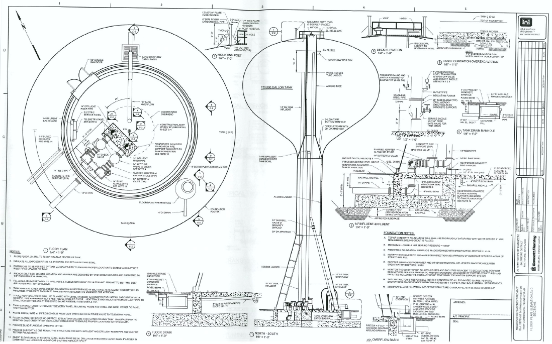

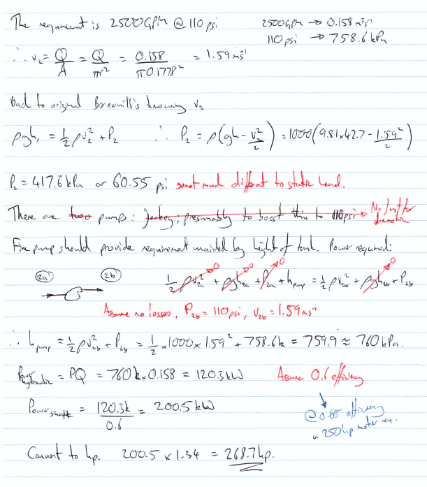
After checking the answer it seemed about right although there were no accompanying design calculations to the contract and drawings so I chalked up my first comment. The rest of the checking passed with less excitement. There were a few clauses that had been missed from the contract, some ill thought out processes and demolition elements missing from the drawings. It seems a common theme though that construction division give the most comments, usually about build ability and, as discussed in the past, what is actually existing at the site.
So what have I learnt:
Hopefully I’ve done Bernoulli’s right; simplify the problem and sketches work.
Designers, it appears, live in a magic construction dreamland and it is always the same build ability issues that are picked up. By using traditional contracts USACE does assume a lot off risk and pays handsomely for the privilege if elements aren’t caught by the construction team prior to tendering. Having recently moved into dreamland, albeit part time at present, the fine detail is easy to forget.
And as ever, time spent on recce…
Oz PCH – Electromagnetic Compatibility Concerns.
Introduction
Within Fredon’s (mechanical installation subcontractor) scope of works, one element is the mech-elec installation works associated with Variable Speed Drives (VSDs) site-wide. After a quality review, conducted by NDY (design consultants), of the standard of installation of completed works, a number of defects were found that were felt didn’t comply in accordance with the mechanical quality specification; of note was the VSD controller cable installation. These were communicated to JHG via a Consultant’s Advice Notice (CAN), which is routine practice.
Fredon did nothing to rectify the defects relating to the VSD cable and so JHG issued an Event Notification. This consisted of a Non-Compliance Report (NCR), raised on JHG’s internal quality management system. This has significant commercial implications for the subcontractor if not resolved in a timely manner.
Issue
The NCR stated that Fredon had not complied with the mechanical specification as the current installation did not include Electromagnetic Compatibility (EMC) glands amongst other issues. The NCR also stated that any installation works completed to-date must be removed and replaced with a fully compliant installation as per the project specification.
Fredon responded as required and provided explanation, aided by technical analysis from their electrical works subcontractor, Electromaster, for their reasoning behind their actions.
They confirmed that whilst they had installed an alternative to the specification, in all cases they meet the fundamental design intent, and in some cases have improved on it.
After a number of meetings NDY stated that whilst it was noted that some aspects of the installation may not comply with the literal wording of the specification, if Fredon were to demonstrate that the installation achieved the technical intent and complied with all associated relevant Standards, then it could be possible to consider the alternative, particularly that the manufacturer’s recommendations had been met.
Technical Background
Fredon and Electromaster put together a technical response on the issues raised in the NCR, in particular, for the EMC gland issue and stated that what they have installed also complies with Australian Standard AS 61800.3:2005 Adjustable speed electrical power drive systems – EMC requirements and specific test methods.
Why is electromagnetic shielding required?
In simple terms, all electrical equipment that has current running through it produces an electromagnetic field (EMF). This field requires shielding in order so that a build-up from multiple fields don’t interfere with other sensitive electrical equipment, especially the likes of those used for recording patient’s vital stats; in a hospital this accounts for a very large portion of electrical equipment and so electromagnetic shielding is vitally important. In addition, on certain equipment like VSDs where an inverter chops up the sinusoidal waveform, inverts it and splices it back together (through switching transistors on and off at a fast rate), this creates Radio Frequency (RF) energy which can be radiated and then coupled onto other equipment’s control and supply cables through either capacitive or inductive means. It can also be conducted to other equipment through a common impedance path such as an earth connection. So, it is even more important to shield cables that come out of VSDs.
How do we shield against it?
In this case we are talking about the motor power cable that runs from the VSD to a motor isolator switch and then to the motor itself. The mains electrical power cable to the VSD, although still carrying current, is not required to be shielded as it will be at 50 Hz and thus the same as other equipment and so doesn’t pose significant interference.
To shield cables a wire braided screen is used to surround the inner core conductor. This shielding impedes both the escape of any signal from the conductor and also prevents signals from being added to the core conductor – thus completely isolating the cable (see fig 1).
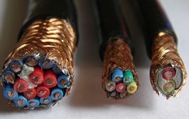
Figure 1. Typical Cable Wire Braided Shielding.
Issue Continued…
Electromaster included the manufacturer’s data sheet for the particular VSD supplied by Schneider which is used site wide; the ATV212W. They highlighted the relevant parts that confirm their installation complies with the standards. So, if NDY are content with this as mentioned then problem solved right? Not quite…
On closer inspection of Fredon and Electromaster’s technical response they highlighted the wrong VSD model and marked-up the installation guide for the ATV212H not the as-installed ATV212W.
The technical prove information was on page 52 of the installation guide, at the bottom of which it describes the ATV212W model and on the following page it clearly describes the correct cable arrangement and use of the EMC plate. Figure 2 shows the ATV212W and specifically states that the cable gland must be ordered separately as it’s not supplied with the VSD.
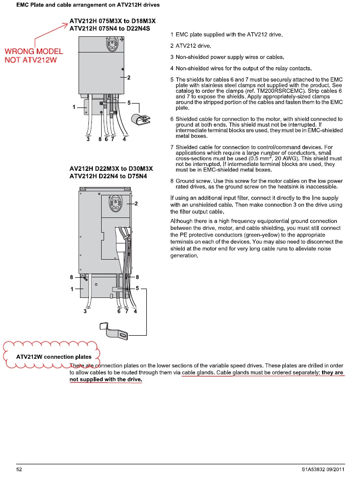
Figure 2. Manufacturer’s Installation Guide p.52.
Figure 3 shows the next page and highlights the need for a metal EMC gland and explains the mounting and connection required to correctly shield the cable and drive.
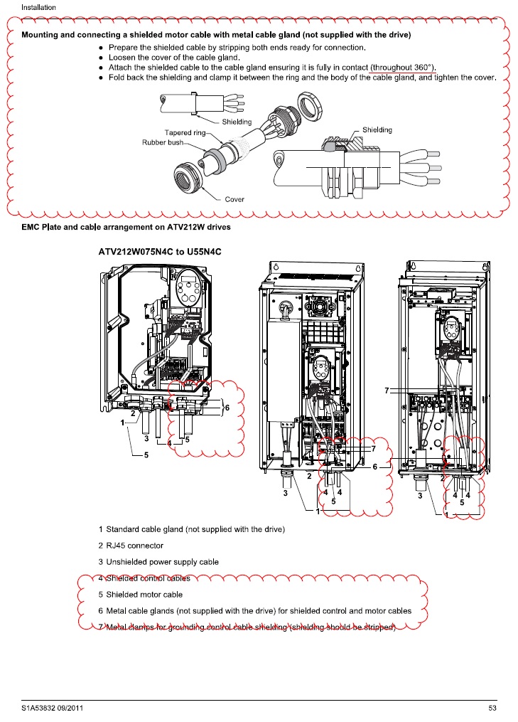
Figure 3. Manufacturer’s Installation Guide p.53.
Why was it installed incorrectly?
My view is that Electromaster have installed the VSD cables based on a combination of factors in order to save both installation time, which equals a labour cost saving, and capital costs. These are:
- Carrying out installations as per what they have previously done on other projects;
- Using standard plastic glands as these are significantly cheaper than metal EMC glands;
- Saving on labour time (approx. half) and thus reducing cost, by installing plastic glands over EMC glands, and;
- Possibly not having even read the design specification.
What is missing from their technical explanation of what they have installed is the actual termination of the motor cable into the VSD. An on-site inspection proved that they had indeed connected to the metal back plate in the VSD housing which is separately earthed, but the connection to the earth bolt was achieved by pulling the wire braided shielding round to one side and twisting it together to form what is referred to as a ‘pig-tail’ (bunched-up strands) and attached to the earth bolt (see fig 4).
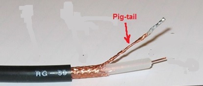
Figure 4. Cable Shielding Pig-tail – Bad Practice.
Figures 5 and 6 show the actual VSD installed by Schneider but wired by Electromaster. It can be seen in figure 6 the use of a standard plastic gland opposed to a metal EMC gland and also the shielding twisted into a pig-tail (heat shrinked in a green sheath) and connected to the ECM plate (earth). If the installation was left as it is then the pig-tail termination of the screening would mean that RF leakage could potentially escape through all the plastic glands seen in the bottom of the drive.
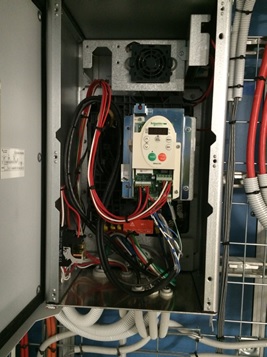
Figure 5. Schneider’s Installed VSD.
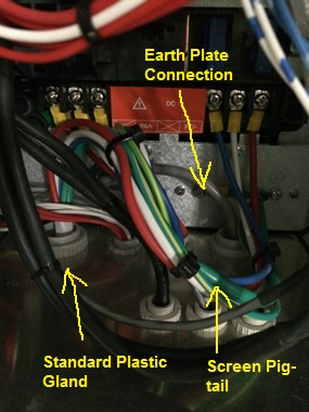
Figure 6. Electromaster’s Wiring of VSD Motor Cable.
The issue with what Electromaster has done is they haven’t completely screened the cable through 360 º, like the examples in figures 7 and 8 show.
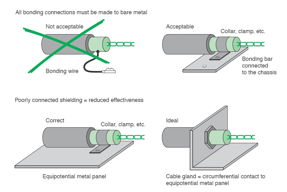
Figure 7. Schneider Electric Earth Connection of Shielding.
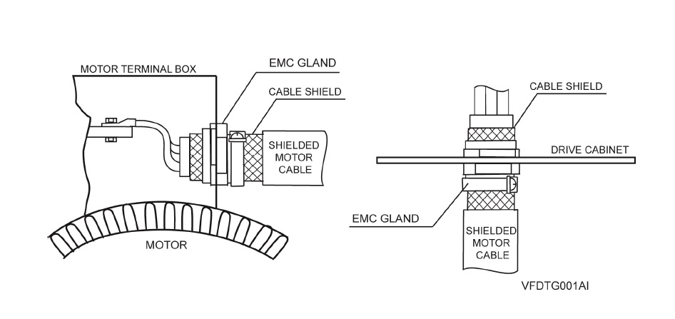
Figure 8. Power Electronics Earth Connection of Shielding.
The reason the lack of 360 º screening is such an issue is that when dealing with high-frequency electromagnetic radiation from an Alternating Current (AC) source it becomes distributed within the conductor where the current density is largest, near the surface of the conductor, and is known as the ‘skin effect’. The electric current flows mainly at the skin of the conductor which causes the effective resistance of the conductor to increase at higher frequencies. Therefore, RF leakage from any unshielded portion of cable can be quite high.
A quick Google search also reveals that pig-tail terminations for cable shielding is a big ‘no-no’. Even if the pig-tailed termination is inside a metal housed VSD (mini faraday cage) then technically the RF can’t escape as long as a metal gland is used. However, Electromaster used plastic glands and so this presents a clear path for any RF leakage.
The Design Specification Intent
The method behind using a metal EMC gland with a metal plate/VSD housing is that the VSD housing acts like a mini faraday cage with a separate earth cable running to ground. Where the cable enters the VSD it is secured in place by the EMC gland with the cable shielding pulled back on itself and the gland clamped around it making a 360º connection to both the shielding and the VSD housing.
The design specification explicitly says that:
Terminate screened power cables at each end in EMC glands to ensure circumferential connection of the screen to earth. Earth the screens of thermistor sensor and motor lockout cables at the converter cabinet utilising metal cable clamps for each cable fastened to an earth bar installed within the cabinet for the purpose or with EMC glands secured to an earthed gland plate externally to the cabinet, as specified by the manufacturer.
Motor isolators shall be 4-pole, key lockable mounted in a die cast alloy enclosure. The isolators shall switch the motor power and control circuits simultaneously. Cable entries shall be fitted with EMC cable glands and earth bushes suitable for the cable types connected. The earth bushes for each circuit shall be connected together with 6 mm2 cable to maintain continuity of screening of the power and control cables.
Resolution and Possible Fixes
One possible solution could have been to swap the plastic glands for metal ones as this could theoretically be adequate. However, Electromaster and Fredon would need to back-up this installation with technical proof of this which may be difficult as all reports on ‘best EMC installation practice for VSD’ state that the use of pig-tails is prohibited.
“A screened cable gland suitably designed and sized for the screened cable type used should be fitted at the motor end. Do not wind the screen into a “pigtail” and terminate under the earth terminal within the motor terminal box. Terminate the earth conductor(s) to the motor earth terminal(s) located inside the motor terminal box. When installing the SD700 directly on the wall (no additional enclosure) a screened cable gland suitably designed and sized for the screened cable type used should be fitted at the SD700 gland plate. Do not wind the screen into a “pigtail” and terminate under the earth terminal within the SD700 terminal box. Terminate the earth conductor(s) to theSD700 earth terminal(s) located inside the terminal box” (Power Electronics 2013).
Therefore, they need to comply with the design specification which is to use specific EMC glands.
So What?
There are approximately 400 VSDs site-wide with motor cables terminated incorrectly. These therefore must be re-worked as JHG have alluded to in their NCR. This has been confirmed by NDY and so Electromaster, via Fredon, must now conduct the re-work.
Costs
Based on the RS catalogue and list price, which clearly a subcontractor will get at trade but fine for comparison reasons.
Capital Costs
The capital costs of switching the glands alone would be in the region of $20k (£10k).
$25 per EMC gland x 800 (2 glands per VSD) = $20k
$1 per plastic gland x 800 (2 glands per VSD) = $800
A difference of $19,200.
Labour Costs
2 hrs per VSD at $65 – $80 per hour = $130 – $160 per VSD x 400 VSDs = $52k – $64k (£26k – £32k).
Total Costs
$72k – $84k (£36k – £42k).
Conclusion
From this example I have learnt a number of points:
- Subcontractors will, unless very diligent, usually default to conducting works how they have always done so on past projects.
- Due to point 1, subcontractor’s work must always be quality checked.
- Subcontractors will try and convince you that what they have done is in accordance with the specification. In providing technical evidence to back-up their installation, if an alternate method had been used, they will may well be proving only half the truth and purposefully omit defective practices.
- Due to point 3, subcontractor’s evidential explanations should always be scrutinised for accuracy.
- In an office block the leakage seen could probably be tolerated but the key issue in this project is that the building is a hospital and if there’s ever a place you don’t want to cause RF interference it’s in a hospital.
In Other News
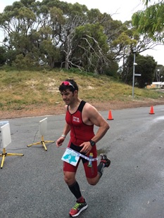
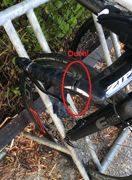
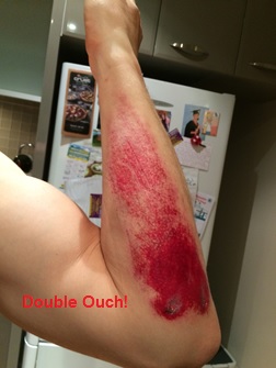
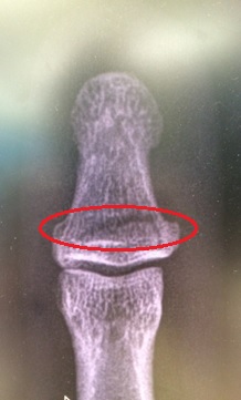
My Ironman (IM) trg has taken a bit of a hit. In a build-up half IM race I decided to trow myself off my bike but not forgetting to do my best superman impression before hitting the deck pretty hard. My initial annoyance was the damage to my bike; carbon fibre is costly! Although pretty battered, bruised and scratched (mainly to my pride), in good old Army fashion, I soldiered on finishing the remaining 20km of the bike leg and the 21km run. Post-race clean-up and a trip to A&E the next day confirmed I had actually broken my thumb; I did feel a fair amount of pain whilst trying to change gear – now I know why.
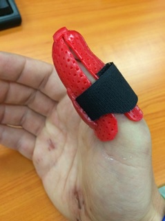
What impressed me most during my treatment was the thermoplastic thumb splint (available in a choice of colours) complete with water friendly Velcro securing strap, although I’ve already got some design mods in mind for version two. It means I can still compete in my next half IM trg race in 2 weeks’ time before the thumb is estimated to be fully healed 6 weeks from now.
Below are some pics…

Changing Seasons
An interesting Chemical Anchor letter in the NCE, link below:
What is interesting about this is the warning which the author gives and the prevalence of these anchor systems on my site. In one case design starter bars were ‘RFI’d out’ of the design in preference for a drilled and epoxied system to be installed at a later time. The rationale being that leaving the starter bars out of the floor room my subsequent work, and was less of a safety issue.
Epoxied rebar to replace CMU starter bars
I had HILTI delivered training which supports the letter; there can be a huge loss of design strength in these systems if they are not installed properly and, by HILTI reckoning only 20% of anchors are properly installed. HOWEVER, these systems can be very effective. So what? If these are specified on your site, or indeed if you end up specifying them as a part of your design phase then just make sure that the tradesmen installing the systems have the correct qualifications and equipment otherwise, as the letter highlights, especially in safety critical applications you may ‘have dramas.’
Changing Seasons affecting Work
The cold weather is encroaching slowly but surely (a bit like my progress towards the finish line of a recent ten miler). This has highlighted a slight lapse in the PC’s QC process in-so-far as there is a cold weather plan for the placement of CMU at my central utility plant, but it is not being stuck to. On a recent cold snap the block had become too cold and the grout samples were not being taken by the specialised testing sub contractor at a representative time. Nor was there a QC rep on site to remediate the issue. As QA acting on behalf of the client I was required to step in; the simple fix being to stick the blocks in the sun for a while to heat gradually and use warm water in the cement mix to maintain the correct temperature (per the plan). I engaged with the QC manager to ensure that as the cold weather becomes more frequent there will be a QC rep on site at time of the key risk, in this case first thing in the morning when the very first blocks are being laid.
False Reporting
I conducted the latest pencil walk last week in conjunction with some of the other area representatives (M&E, architectural). There have been some discrepancies in the PC reporting, including the reporting of percentage completion of a scheduled activity which doesn’t tally with the expected remaining duration. It seems that it is easier to project the cost of an activity rather than its expected duration. At present activity percent complete is reported and agreed, and the remaining duration and accrued cost of the activity is calculated. For payment this is fine, because the payment estimates are fairly accurate but for remaining durations it is not working. This is leading to a false representation of the project completion, which is what the client, hence USACE is interested in. In some cases (my CMU for example) the original duration was estimated at 15 days, based on a 5 day calendar. It has been going on for almost 2 months now. It is around 65% complete, which means that the computer thinks it has around 5 days left to complete before the successor activity can proceed… In actual fact the successor activity can’t proceed for, in my opinion, another 15 days. This will eat into the activity float. Not a problem for my CMU, which has oodles of it, however if an activity with less, or no float has this issues then the critical path might be affected. The PC now has to walk through and agree actual remaining durations with USACE on future pencil walks to ensure the accuracy of reporting. This will help more accurately reflect the contract completion date. Below is an example of the issue – the overhead HVAC has an original duration of 40 days, is 25% complete yet has an anticipated actual remaining duration of 60 days.
Example from pencil walk
Note for Phase 1s
As you’ll know from visiting my site yesterday I have just one week left on site. Damo and Olly a little more, Dan and Daz a little more again. So if you want examples of things we’ve seen to put what you’re learning into real life context, photos of stuff we’re doing, or even just to ask about how we find our attachment locations, now is the time to ask. I am very happy to provide photos and answers and I’m sure the other lads are too. But get in fast as time is short!
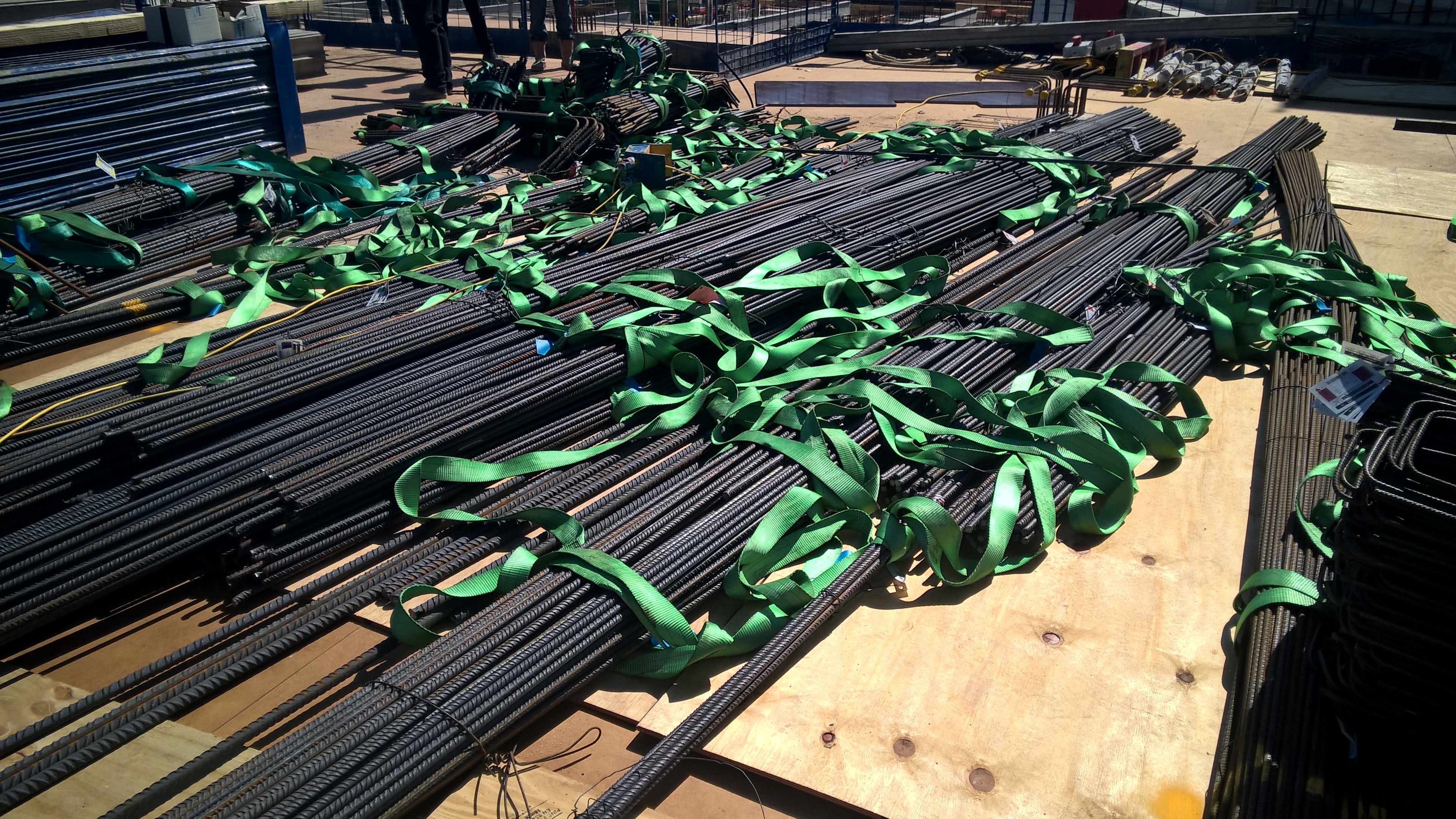
Here is a picture of the steel as it gets delivered as a starter (requested by Richard):
Two Fifty One – Concrete continuity
Two Fifty One – Concrete continuity
RC Detailing.
By way of background, Two Fifty One has two levels of in-situ basement followed by 40 storeys of precast concrete to form the tower superstructure. The lateral stability is provided by shear walls which form a perimeter around the lift and stair shafts.
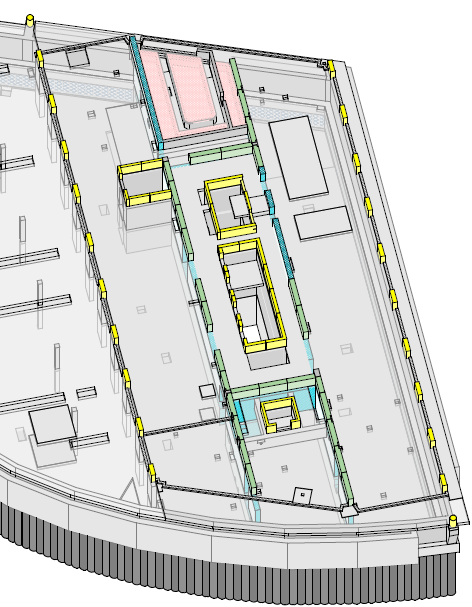
Substructure – The green walls represent the shear walls in the tower. Inner yellow walls demote lift pit and stairwell.
The slab to shear wall connections in the tower basement floors have been designed using kwikastrip. These are pre-bent bars that sit within a case and then are bent on site at a later date.

Kwikastrip pull-out bars
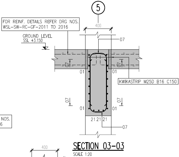
Kwikastrip used to form wall to slab connection joint.
The more typical method would be to run slab steel through the walls as shown in the figure from the IStructE Standard Method of Detailing Structural Concrete.

The reason is to enable the walls to be poured in higher strength concrete than the slabs. This is because the walls carry the loads down the building to the raft foundation to the piles below. From a buildability perspective it means the walls need to be cast to the structural slab level (ssl) rather than to the slab soffit. Other than the fact the falsework had initially been designed to soffit level this not a problem.
One of the key considerations of using pull out/continuity reinforcement bars is the rebending of the reinforcement.
Bending reinforcement on site presents the risk of overstressing the steel by bending it to too tight a radius thereby weakening it.
The bar diameter of kwikastrip is limited to 16mm and a bar bending tool should be used to rebend the reinforcement. The IStructE Standard Method of Detailing Structural Concrete states that “where it can be shown that the bars are sufficiently ductile (kwikastrip uses Class B steel so is acceptable) bars not exceeding 12mm size may be rebent provided care is taken not to reduce the mandrel size (radius of bend) below four times the bar size”. The same is also be true for 16mm steel at seven times the bar diameter.
This requirement needs close quality control to ensure bars are rebent correctly. The walls use both 12mm and 16mm steel kwikastrip making it even more important not to confuse the bar diameter with bar bending tool (or the strips themselves). Halfen (kwikastrip supplier) state: “the straightening tool is a steel tube with a specially shaped end and an internal diameter only slightly greater than the diameter of the bar to be straightened” hence strict quality control is needed to firstly use the tool (rather than any old scaffold tube) and secondly use the correct tool.
Other considerations include:
Increased time to fix the items in (fiddly).
Procurement ordering time – the items need to be ordered specifically, not called off from reinforcement schedules which requires lead time and storage.
Increased cost (circa 8k for one level of slab) compared to extending the reinforcement bars a short distance. Cost of standard stock steel per tonne is less than equivalent of weight of kwikastrip.
The structural requirement to maintain concrete continuity has overridden the practical installation disadvantages and that is how it will be built.
Other points
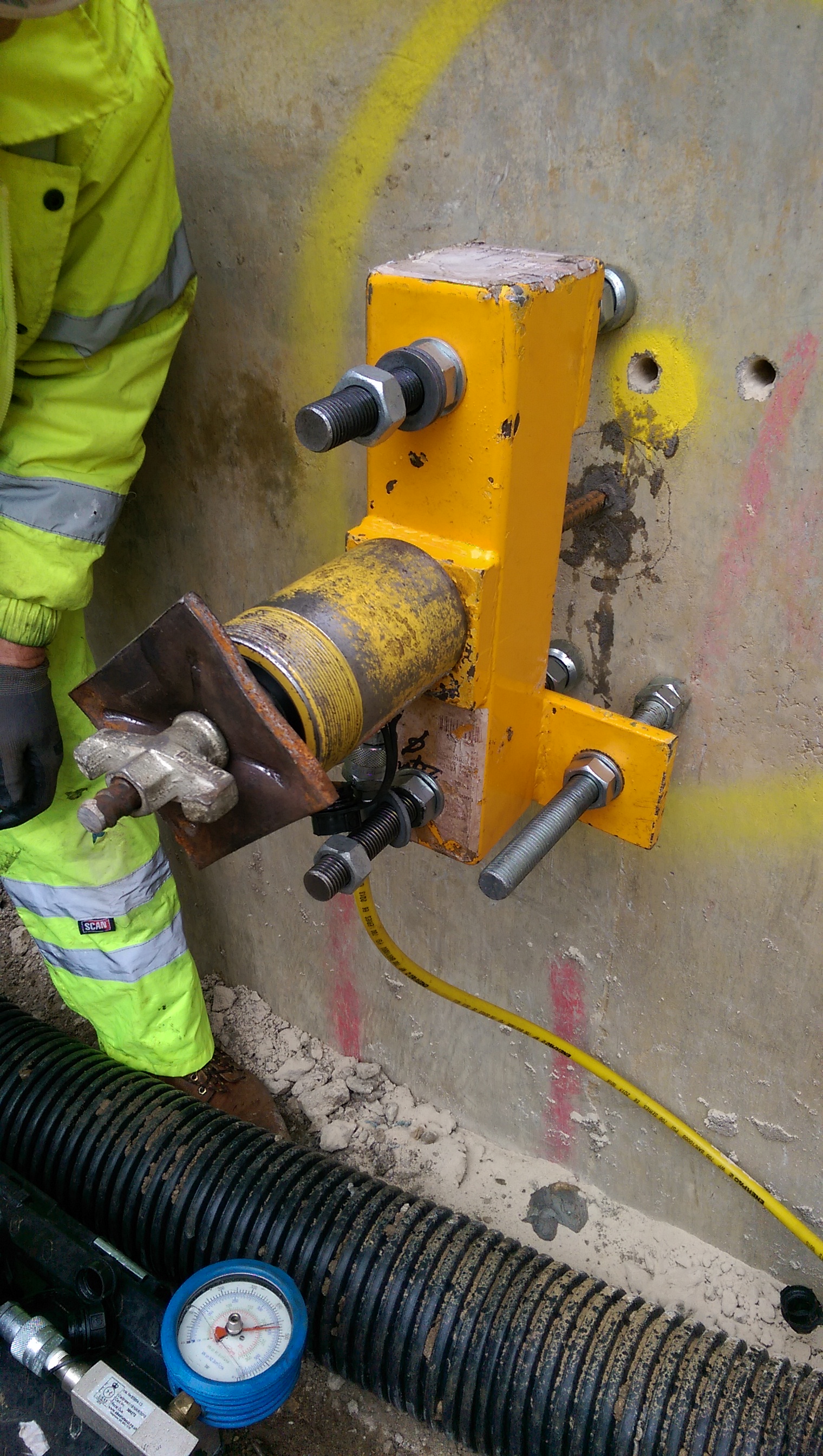
Pull out tests. We want to use an existing retaining wall to resin in dywidag bars to connect a one sided shutter to form a new retaining wall. We will be using Peri shutters with pre-set tie bar positions. The pull out tests showed no movement at 150kN, other than a bit of feet penetration into some old plaster on the wall. At 150kN there was a crack sound as the resin slightly debonded from the concrete and at 200kN there was evidence of some a cone failure (see circular crack around bar). The aim was to confirm a 90kN force would not be exceeded which the tests proved was the case. Interestingly the critical factor in pouring the walls will now be the pressure on the formwork soldiers and walers, rather than tie force. Therefore the rate of rise will be controlled especially because we have retarders which increase the pressure exerted on the formwork.
Propping scheme. The view below shows the site with the props spanning over the basement. In order to remove the props the basement level 2 slab must be cast halfway between them. This was creating a bit of a pour sequence issue as clearly the props are not angled in a way which suits the foundation layout!
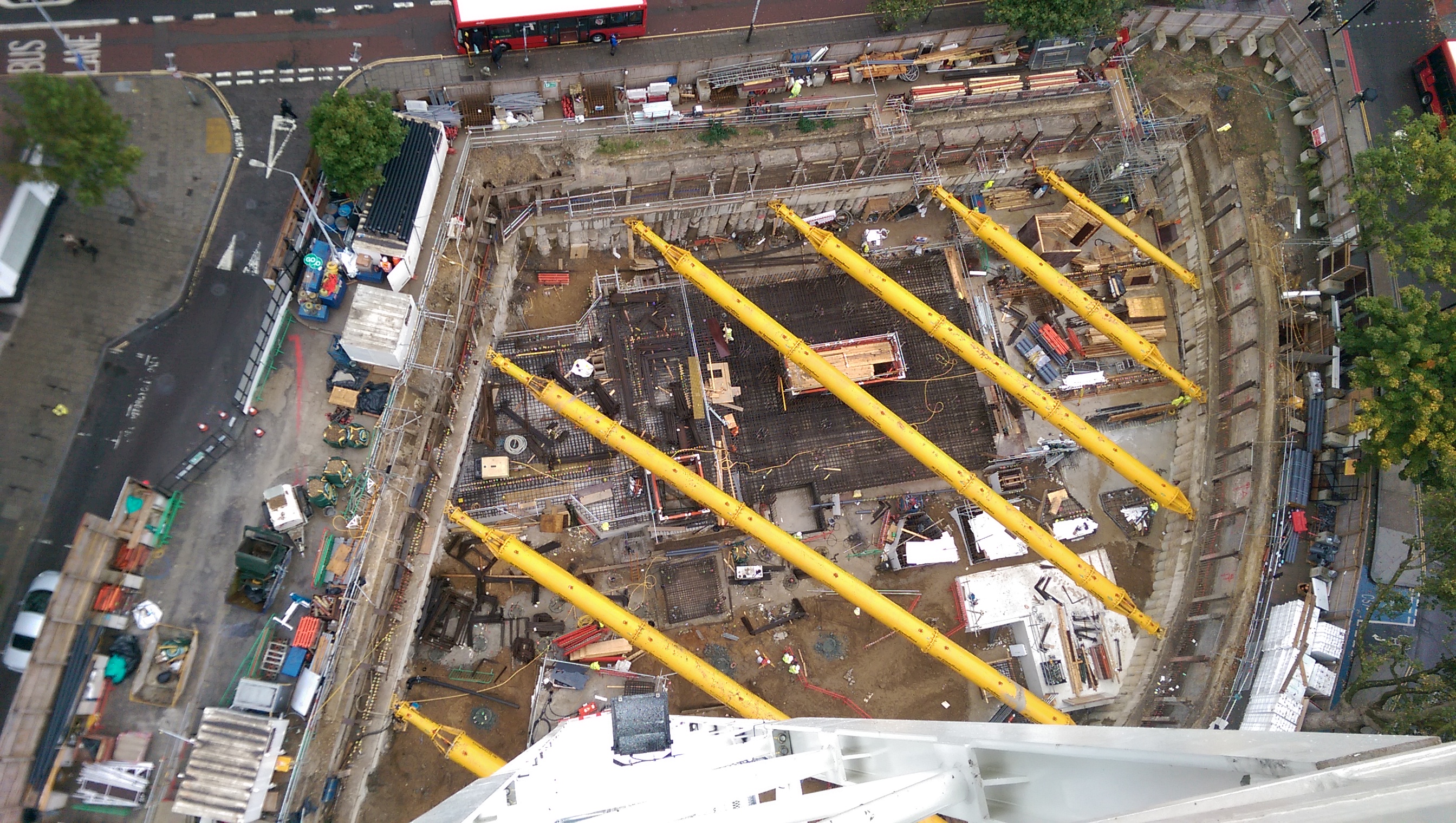
Two Fifty One from our first of 4 tower cranes.
H&S – executing your plans
One of Guz’s recent blogs identified the difference between civilian and military idiots being that our idiots do as they’re told. This blog aims to echo that point and manage the expectations of those in phase one who are no doubt already chomping at the bit to be released into the wild. In the hope of giving something worth taking home, I urge you not to consider the health and safety box ‘ticked’ just because you have written a risk assessment and method statement.
We hold a pre-start meeting every day to brief the workforce on forthcoming activities and highlight any areas of concern (almost always H&S). This week we identified that as the shafts get deeper, the risk of carbon monoxide poisoning from plant operating at the excavated level increases. To reduce this risk, we have installed extractor fans to suck exhaust fumes out of the shaft. Should that fail, we have gas meters at the bottom of the shaft. Flashing lights on the meters indicate danger levels have been reached and work must cease until safe levels have been restored.
These meters have no audible means of alert, and are only useful if you can actually see them. The workforce was hanging them down the shaft off a piece of rope tied to the handrails at the top of the shaft. The problem is that the meter cannot be seen when the excavator is facing the other way. To mitigate the risk of the operators not recognising danger levels, we instructed the workforce (in the pre-start meeting) to place the meters in the cabins of the plant. A couple of hours later and they had already forgotten (figure 1). Note the meter hanging from the handrail. Civilian idiots don’t listen.
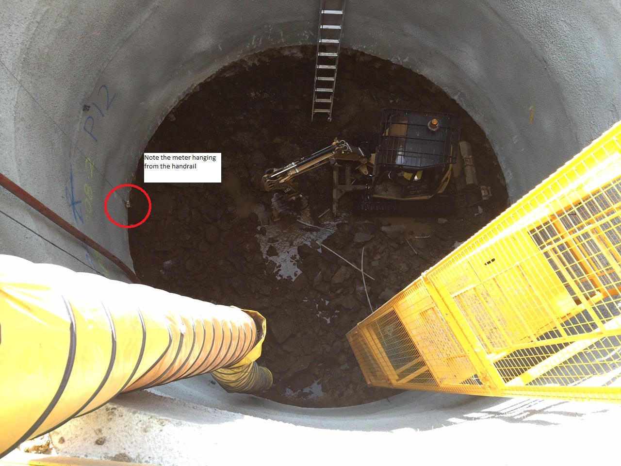
Figure 1. The red circle indicates the gas meter hanging from the shaft handrail
In addition to this, we had a working at heights issue. I produced the AMS (Activity Method Statement) for shaft excavation. This included shaft access and the introduction of a bespoke shaft access system which we had fabricated specifically for this project. The theory behind this system is that it offers both safe access to (and from) the excavated level, and a safe haven for the workforce when muck is being craned out. The PM was keen to eliminate the need for the workers to evacuate the shaft every time the kibble (skip) was craned in/out of the shaft in an effort to increase productivity (the crane costs $1600 per day).
You will identify the mesh cage surrounding the structural elements of the tower which also eliminates the need for a fall arrest or restraint system. Descent/ascent ladders are placed on alternating sides for each segment installed i.e. climb on the left, walk across to the right, climb on the right, and so on (figure 2).
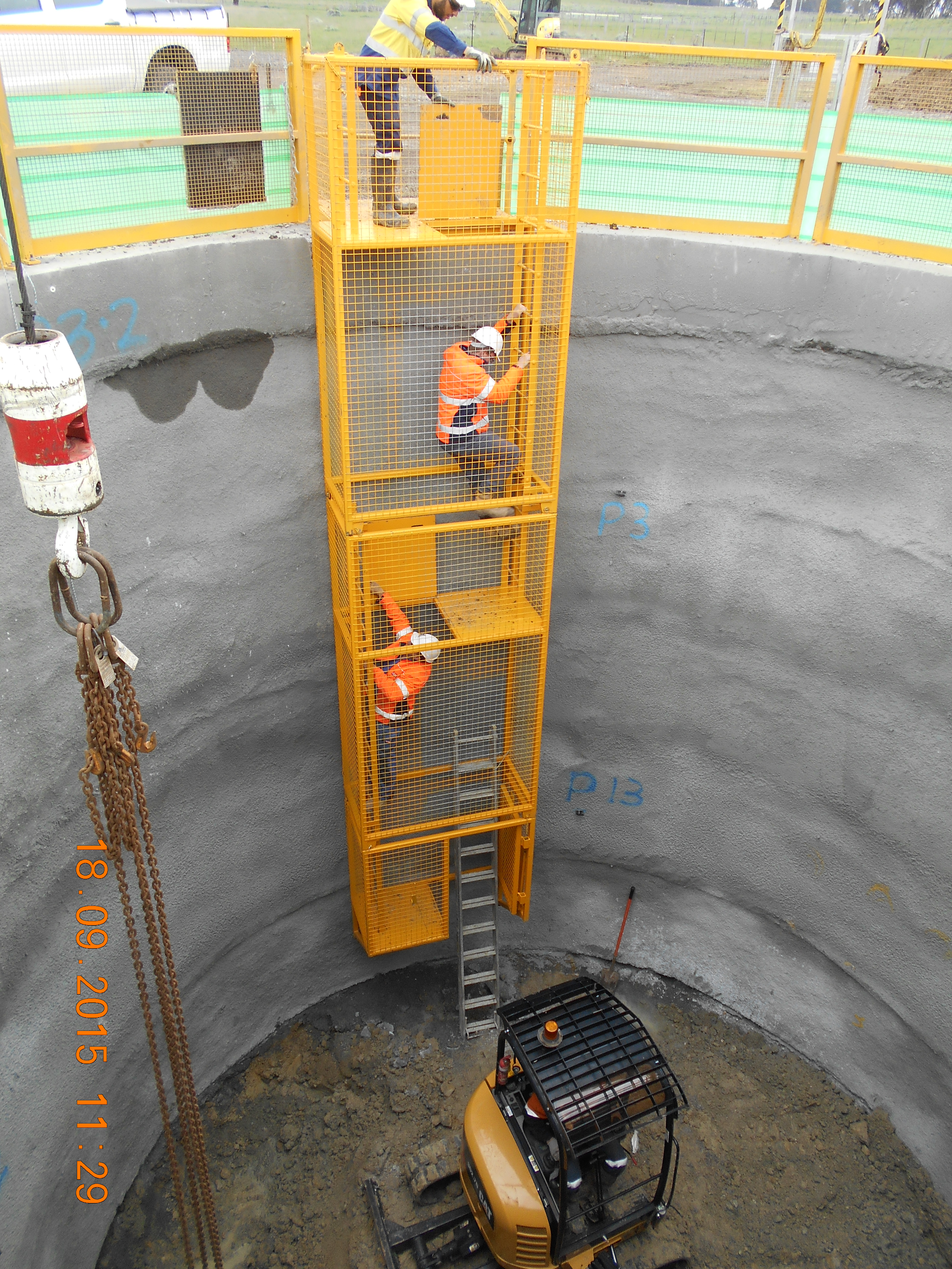
Figure 2. Correct layout of the access tower. Note the alternating ladders.
I inspected a shaft today to calculate the volume of concrete required for the base slab which signifies the end of billing works to my shaft excavation cost code. The tower had been installed such that there was no alternation between segment platforms i.e. falling off the ladder would see a re-enaction of the opening scene to cliffhanger. – the tower was effectively nothing more than a 6m ladder (figure 3).
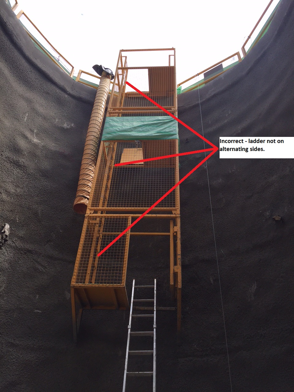
Figure 3. Incorrect layout of the segments (not alternating). It’s a 6m drop from top to bottom with no fall arrest system.
In conclusion, civilian idiots don’t listen. The workforce failed to implement two critical (and simple) measures designed to reduce and mitigate the risk of harm to them. To those who have not dealt with ‘simple’ workers (probably your average Australian) yet, brace yourselves. Delivering toolbox talks and pre-start meetings ticks the boxes at management level, but failing to follow up through regular inspections nullifies your efforts.
On a lighter note, I caught a redback spider yesterday. My JHG one-up knows to expect her in his stationery drawer if he gives me any more shit jobs (figure 4)

.Figure 4. Meet Mrs Amaroo – keeping shit jobs away
Adding water to concrete on site!
I have mention this in an earlier blog however, Richard asked me to highlight this again as he’s currently delivering the concrete package.
The practice of adding water to a concrete mix in order to brings it’s slumps back inside tolerance is poor at best. It alters the water/cement ratios and affects the whole mix, however, we are allowed to add water on site!
The concrete specified for our bridge is a C40/50, 20mm limestone mix. The limestone aids with the strength but also assists with ensuring that no chlorides are in the concrete which would cause long term PT tendon corrosion issues.
The problem is that limestone draws moisture out of the mix at a hell of a rate and during the trials we had real issues in maintaining a workable mix. Plasticisers and retarders have been added but altering a mix is not as simple as adding more….
As a result, the supplier monitors the mix, travel time and ambient temp and provides a certificate that details how much water we can add to each load. Every load that arrives is different and ranged from 0 to 72 litres (the most I’ve seen to date). Very rarely do we have to add this, normally the slumps are within tolerance but when loads get held up or arrive marginally out of spec, it has allowed us to keep batches alive.
Today’s pour should have had a 180mm +/-20mm slump but one load was measured at 130mm. The ticket specified up to 33l could be added. I added 10l to a 6m wagon which brought the slump up to 190mm, a little water makes a big difference.
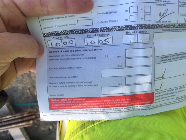
Concrete ticket – max additional water is marked on every ticket

Water gauge – For QA we have to monitor how much water is added.
How it should be done
To follow on from Daz’s excellent piece on tendering (if you haven’t read that, read it first), I thought I’d throw in my recent experience of procurement…
The architect, PDP, have design responsibility for the waterproofing, including the additional waterproofing measures required for the Grade 3 basement areas. PDP should provide a waterproofing intent that is then given to the geotechnical designers to analyse. Arup, the geotechnical designer, should furnish PDP with values that are used to define the performance requirement of the waterproofing measures. These figures should be applied by the architect to a catalogue of products and define a product. The supplier of that product are then responsible for the detailing of that product, the supply and installation.
None of that happened.
Instead PDP drew a waterproofing intent and went direct to the supplier approved by the client, Grace, to design the cavity drainage system. Grace (not Newton, sorry Henry) said they couldn’t do it. They could specify the product and do the detailing but they couldn’t do the pumps. Hoare Lea, the M+E designer, should have then been approached to do the pump design. Instead PDP went to a different supplier, one not approved by the client, Newton, and asked them to design it all. Which they did. At this point it is worth noting that PDP did not pay Newton for this design.
Sir Robert McAlpine (SRM) are now stuck with a design that is not approved by the client. The sub-contract for the supply and installation of the waterproofing does not include a cost for design. So that cost (and there must be one) must be included within the rates in the installation subcontract since no one does anything for free. In order to maintain the programme, the waterproofing has now been installed, so we’re far too far down the road to go back and do it properly so what can we do?
It looks like we’re going to have to either suck it up and accept that we’re effectively paying for the design twice (once to PDP and once to Newton), or we have to break down the sub-contractor’s quote and remove the element of design and contra-charge that to the architect.
This dilemma is currently sat with the package QS. Who has been saying for 3 weeks that he will do something about it, but hasn’t. This morning he handed in his notice so I somehow doubt this still sit’s in the Urgent and Important box on his list of things to do!
More to follow me thinks…
Tendering – managing risk with agreements and seeking opportunities through compliance
Yes, I have been hiding. Nothing to do with the Springboks getting beaten by the Japanese, I promise. Anyway, given my exposure to the tendering side of life early on in phase 2, I’m going to share my thoughts for the benefit of those who may not have had the “priviledge” yet, and offer a practical example of how not following the trodden path can produce results on site.
As a reminder, I arrived at JHG at a time when the project had not yet started on site (the head contract had not even been signed). A lot of my time was spent tendering. This is quite a process in JHG that, to me, often borders on spending more time trying to show due diligence than just getting the job done. You could argue that I am being typically cynical, but hear me out.
STANDARD FORM AGREEMENTS
The first decision point when choosing the agreement method is whether labour, consultants or on-site work other than delivery is involved. If none of the above apply, the standard JHG agreement is either a purchase order or supply only contract. The monetary value further defines the agreement to use.
Purchase orders are used for minor supply materials, items, plant and equipment of simple well established specification with uncomplicated delivery requirements, and “off the shelf” items up to an indicative value of $100k. On the Amaroo, these have typically been used for water pipe fittings and steel reinforcement.
Supply only contracts are used for supply only where no installation by the supplier is involved. It is used where the supplier has a design liability or design component fabrication or assembly requirement pre-delivery. Major materials such as concrete and quarry products (crushed rock in our case) which have a project value exceeding $100k and more stringent quality requirements are better suited to this agreement over a purchase order. The bespoke shaft access systems were procured using this form of agreement (figure 1).
Figure 1. Bespoke shaft access system procured off a supply only contract.
Returning to the first decision point, if labour is involved, a short form subcontract agreement or standard subcontract is used. These too are also value dependant.
The short-form subcontract agreement is used where the indicative value is less than $500k and where on-site work is involved. It is used on low risk, low criticality works which are more usually more routine and less complex. It is tailored to key Head Contract conditions and improved where possible. I have used this agreement with the traffic management company to hold lollipops while I track heavy plant over main roads between shafts. A short form agreement is much simpler, I liken it to brevity over waffle. It is quickly produced and signed and returned by the willing SC.
The Standard Subcontract is used for subcontracts over $500k, where on site work is involved, and the risk and criticality issues need to be taken into consideration. It also requires tailoring to the key Head Contract and improved where possible. We have used a standard subcontract with the ‘drill and blast’ company due to the niche capability – they are not quite ‘RE P for plenty’ (figure 2).
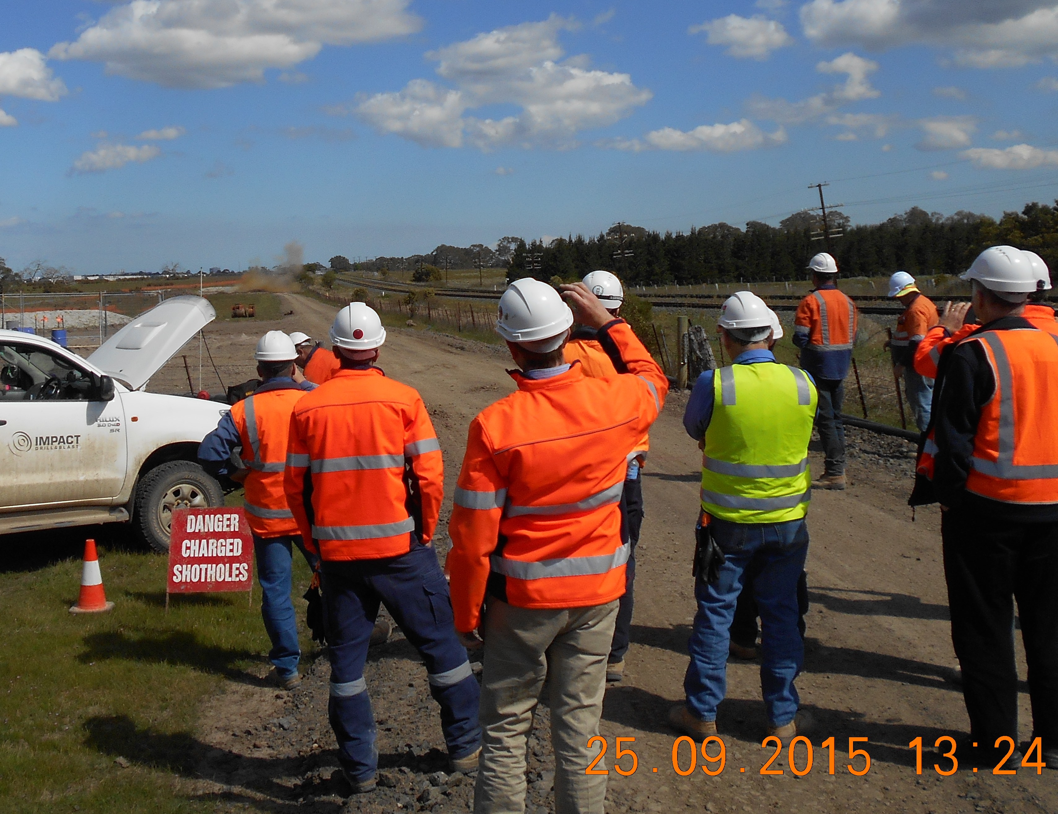
Figure 2. Impact Drill & Blast have been engaged on a JHG Standard Sub-Contract.
The benefits to JHG of a standard subcontract are that they are water tight, and heavily favour JHG. The catch is that they take hours to produce when done properly and are so heavily ‘legalese’ that the SC rarely actually reads or understands the document. They usually just sign it as work is scarce and JHG is a tier one company (a cash cow). This could be viewed as a benefit to JHG, but the amount of time spent answering SC questions afterwards when the information is in the contract they have already signed is startling. Not dissimilar to any one of us signing up to Vodafone. Another disadvantage is that if a SC has legal advice, it usually results in a game of e-mail ping-pong lasting days, if not weeks.
The agreements mentioned above are the most used on the Amaroo, although there are more e.g. plant hire and labour hire agreements.
TENDERING
When putting a package on the market, JHG invites at least 3 parties to tender. They then return their quotes for analysis along with the agreement. The key is to find the best value for money over the best price. I was caught out early on by recommending a street sweeping company with the lowest hourly rate. I had failed to squint at the fine print and note the minimum hours per call out which resulted in them being more expensive. A newbie in the area, I did not take the time to investigate the location of each of the companies to ascertain likely response times. The main effort is to ensure we clean any mud off the roads in the quickest possible time so that we do not upset the local community. My first recommendation was twice the distance as the company that turned out to offer the best value for money. We aren’t talking huge sums, but every little counts with my Scottish Project Manager who wouldn’t even pay for the CI’s dinner out of the project entertainment cost code!
Once recommended (internally within JHG), the subcontractor (or supplier) is set up on the project commercial pack by the commercial team and business can commence. In terms of planning, One week is considered a quick turnaround, with four weeks not uncommon on the 60 something agreements the project has with other parties.
CODE COMPLIANCE
In addition to tender analysis, potential subcontractors must be building code compliant. This is a system used to weed out the sham contractors. A questionnaire is sent to all potential SCs which they fill out and return along with a signed copy of the SC (or their seldomly amended version for our review).
The issue lies in the ability of the potential SC to correctly complete the BCOC questionnaire. It effectively eliminates the opportunity for small companies to win parcels of work as they don’t have the legal expertise to offer guidance on completing the form. It is not an overly complicated process, but it is time consuming and not exactly written in Layman’s terms.
So why does JHG do it? The simple reason is that if they did not, they would not be eligible to tender for government projects (BIG cash cows). You could be forgiven for thinking that it is a sensible step taken to show the AUS Govt that you are squeaky clean (benefit, right?). The disadvantage is that it constrains JHG when it comes to the tendering process and effectively does a full circle; we put the package on the market and land up going with who we always knew we would go with because no-one can be bothered to invest the time and money seeking legal advice to fill out the form only to be haggled to the bone once they are just about awarded the contract.
But there are exceptions to the rule. I had an issue excavating one of my shafts; we encountered an intact rock mass of very high strength basalt which our 3T (and then 5T) excavator could not break out. Blasting was not an option as said shaft is adjacent to a water sewerage treatment plant. Options are reduced to using conventional mechanical means. I chose to crane in a small drill rig to core 100mm diameter holes in the layer of high strength fresh basalt, and then use a rock splitter to create man-made discontinuities in the rock mass. This eliminates the relevance of the material strength. The issue was that the only company I could find with readily available plant was a small company without office support. In haste, the gentleman did not fill out the BCOC questionnaire correctly. A phone call confirmed he did not have the expertise or resources to fill the form out and therefore appeared to be non-code compliant and therefore not eligible to win the work.
I set up a meeting in our office where he was able to use JHG’s legal team’s advice free of charge in an effort to establish whether I could ‘make things happen’. It turned out that he was code compliant after all. We awarded him the work and he started solving our problems in the shaft.
To conclude on my cynicism in para 2, it appears that by not being a robot you can actually get things done. I agree that there is a need to keep the cowboys out, but a common sense approach goes some way to recognising those who shouldn’t and those who can’t without a bit of help.
