Archive
Health and Safety – go nuts!
In the last few weeks we’ve had a few incidents where stuff has fallen from height. The list of “stuff” includes a helmet, a 7 foot scaffold tube (which it a bloke’s arm), a screw jack, a sheet of plywood, reinforcement spacers, a length of rope, a section of edge protection barrier and a bolt. The length of rope was actually thrown off the side of the 6th floor intentionally!
It could be worse, on McAlpine sites across London so far this year even more stuff has fallen including: a scaffold board, a drill bit, a washer, a mobile phone, a metal plate, a brick, a lifting strop, 225mm concrete core, scaffold spanner, sheet of insulation, a pallet truck (how?!) … the list goes on. 95 objects in total. And that doesn’t include the bloke who fell off a scaffold!
In an attempt to curb this we got everyone together and gave them a little presentation about how bad it is when stuff falls from height. The presentation will be given to them again in their own language too, which will be a significant undertaking considering the number of languages spoken on this site.
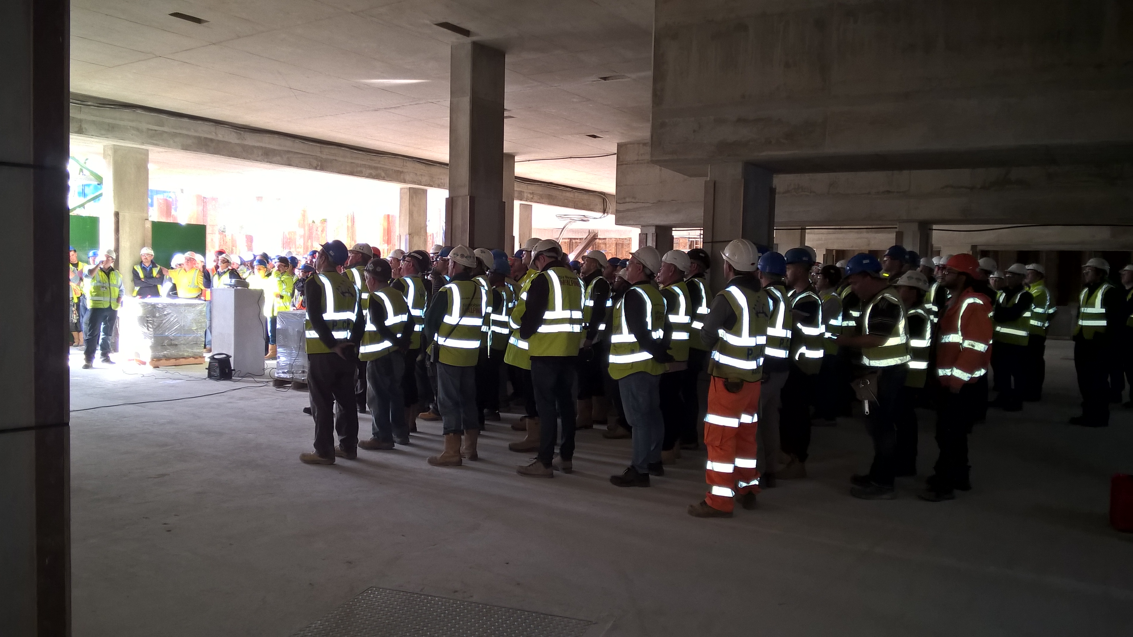
When walking away from the presentation I hear one scaffolder turn to another and say: “The thing is though mate, their not accounting for stupidity!” But he is wrong. These issues are not caused by stupidity. Well not all of them anyway. Some of it is an attitude problem. I’m sure we’ve all been to places where the value applied to life is less than it is here. Some of the people from that place have come here and now work in the construction industry and have brought that attitude with them. They’ve done it that way wherever they’ve come from and that’s what they’re used to. This is not to point a finger at migrants. Some of the old and bold from the construction industry are just as bad. Others do dangerous things because they are too lazy to do the right thing. I saw a bloke climb over a barrier because he couldn’t be bothered to walk around it. It’s not about nationality, or intellect, it’s about discipline! I’ve said this before and I’m sure I’ll say it again: at least in the Army all the idiots do as their told!
One problem that we have is that there is so much construction work in London that there is a serious shortage of competent skilled labour. We have forced our blockwork contractor to only use their own full time lads, not agency, in an attempt to ensure that the quality is maintained. Other sub-contractors have not made the same commitment and so staff turn-over is high as workers move around to whichever site is paying the most that week. This has a serious impact of things such as quality, but also safety as it takes time to indoctrinate the new workforce into the McAlpine way to doing it.
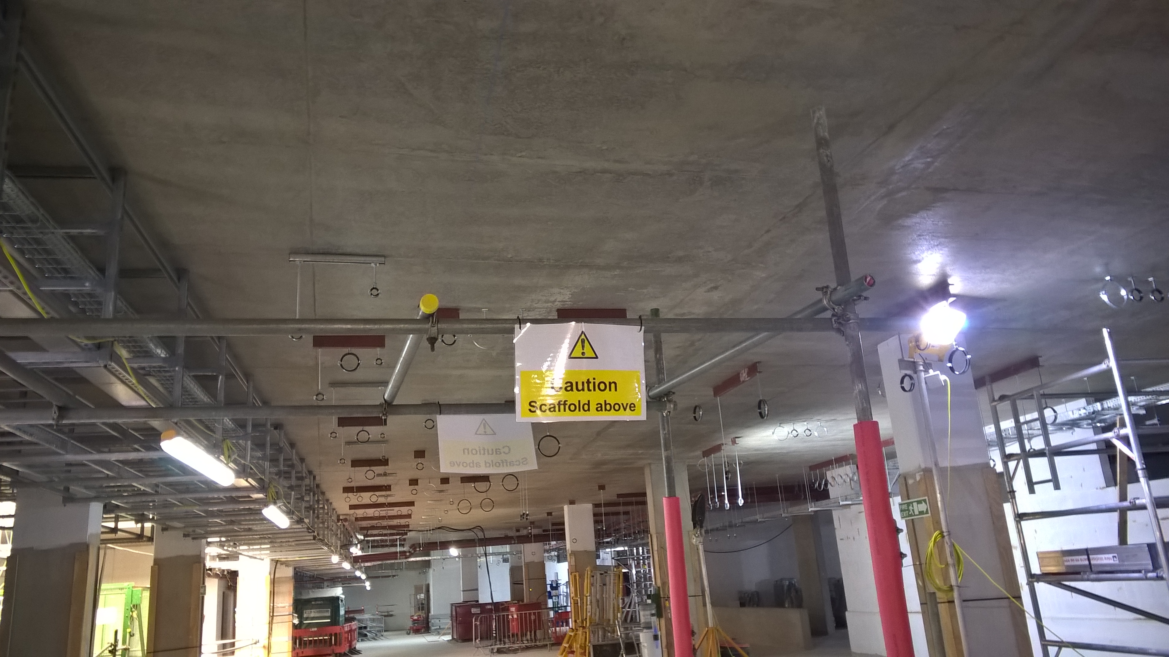
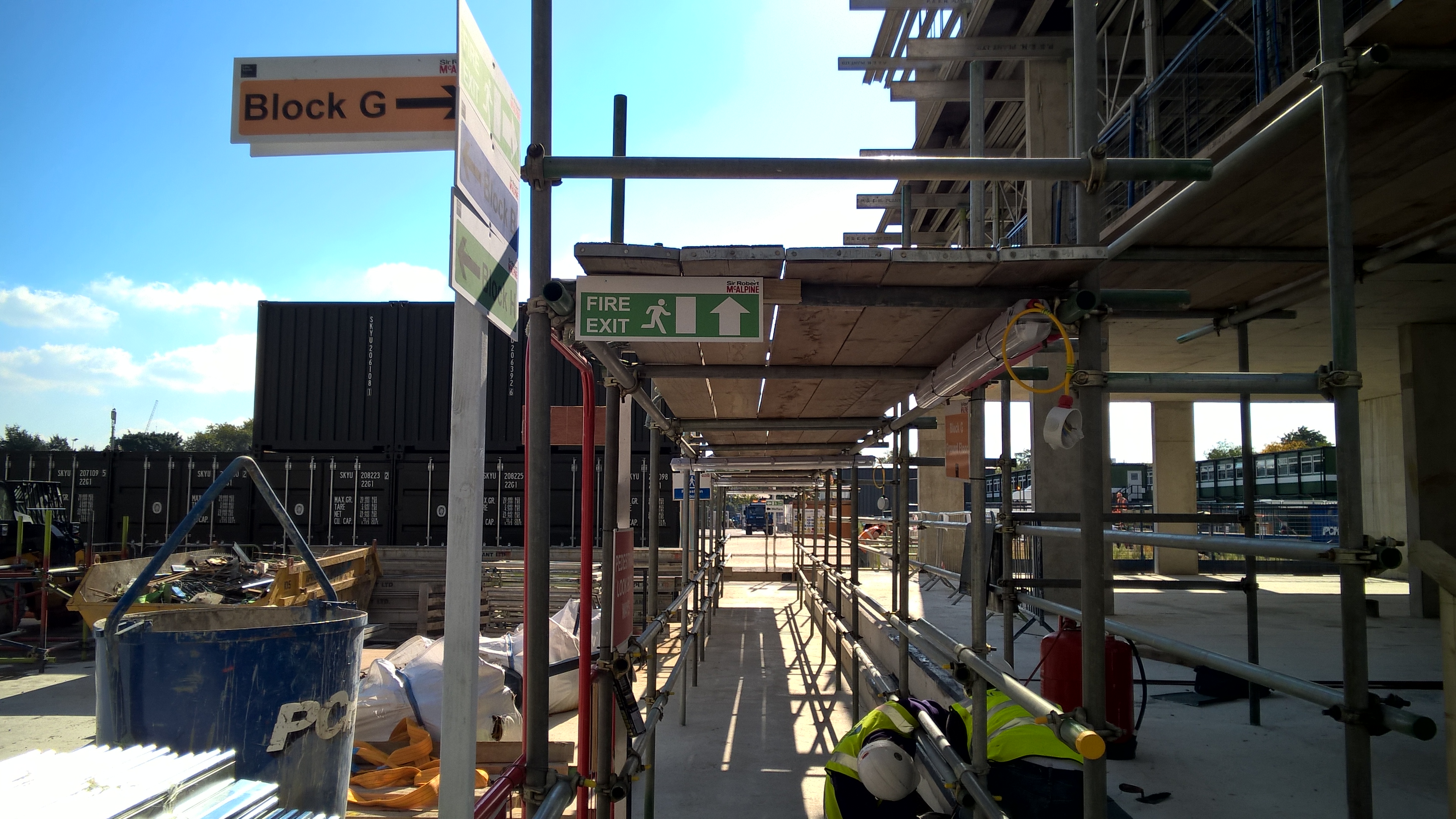
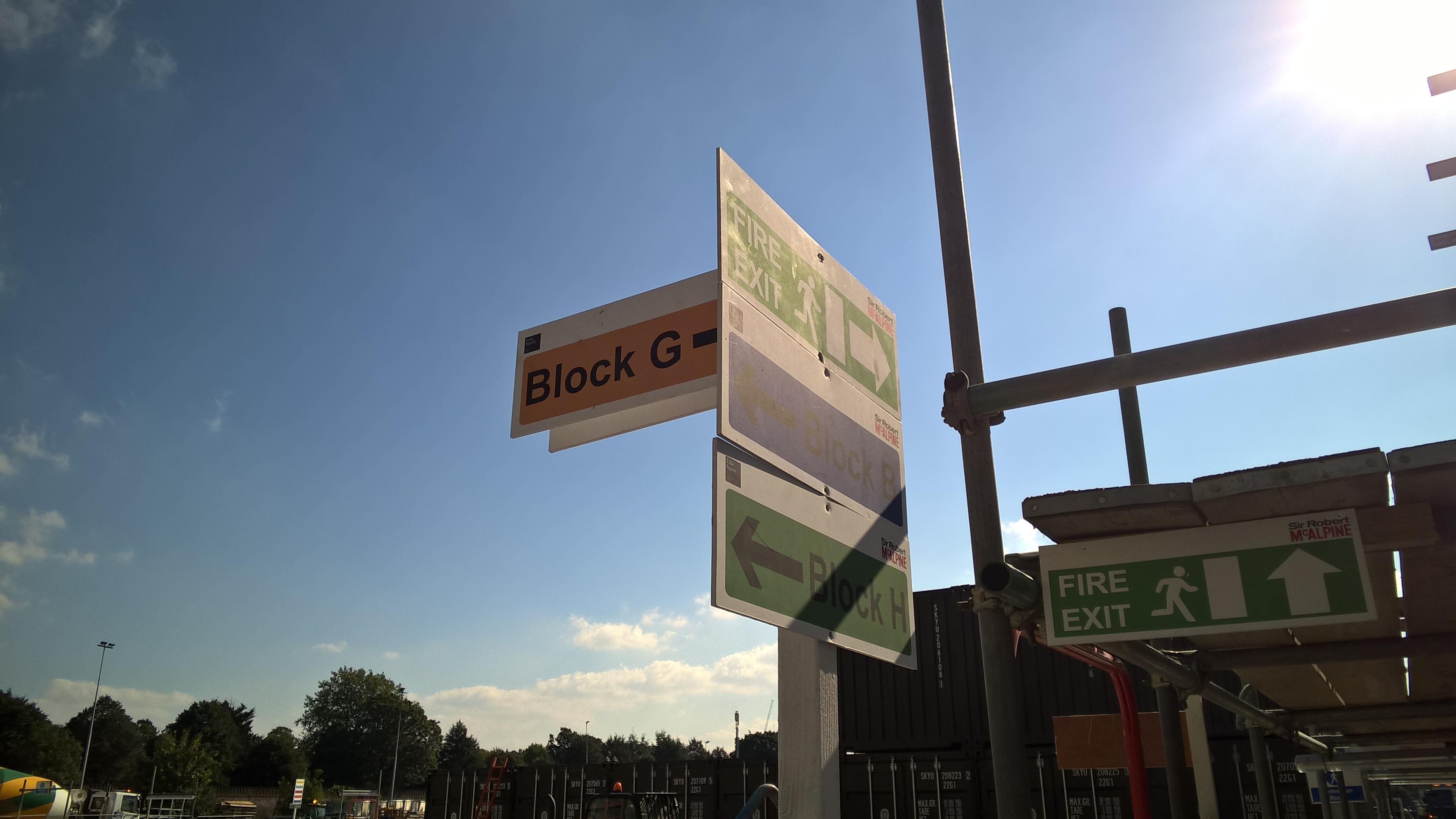
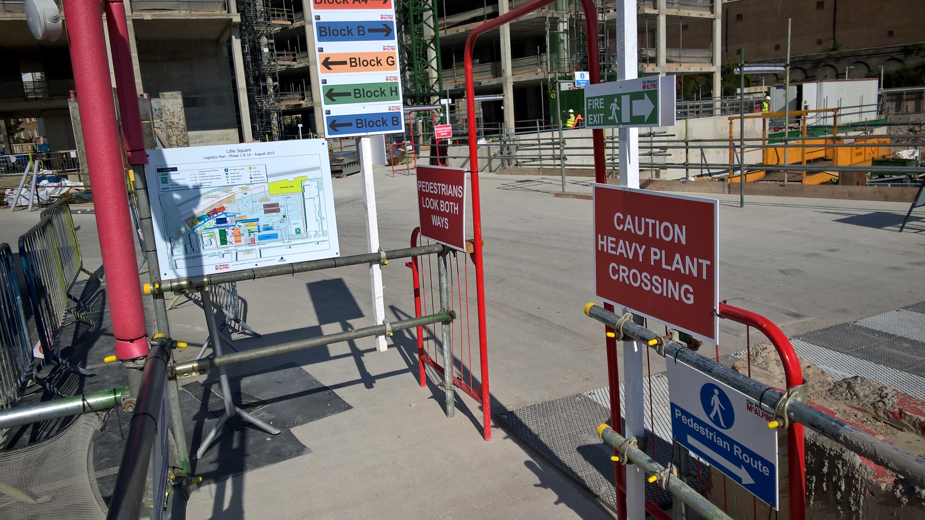
In others news: Our site now looks like a small child has got a sign making kit for his birthday and has just gone nuts!


Oz PCH – Commissioning of Chilled Water Supply from Central Energy Plant.
Introduction
This blog follows on from my previously explained, Chilled Water (CHW) pipework flushing blog. It takes the discussion further, explaining the CHW system, commissioning and project wide examples of applications including problems faced.
The CHW System
Fig 1 shows the main plant: flow and return connection to CEP CHW, the mixing decoupler, flow meters, the pump sets in an N + 1 arrangement (n = 4 pumps duty), the four flow and return legs that feed various risers and the critical to life pump sets and flow and return legs.

Fig 1. Plantroom 10 (Basement) CHW Equipment Layout.
The total flow rate for all four legs is 605.1 l/s. Fig 2 shows the N +1 pump sets with 4 x duty pumps (rated at 125 l/s each) producing 500 l/s; the 105.1 l/s delta (17%) is for system diversity.
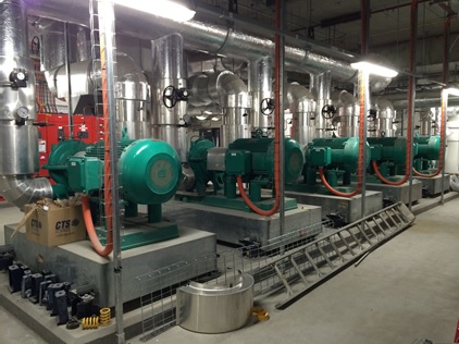
Fig 2. Plantroom 10 CHW Pump Sets.
The CEP design flow temp is 7 °C and return is 14 °C.
The following main equipment is fed by the CHW system:
Central Computer Room 2 (CCR2) – This is the main communications hub of the building and houses sensitive electronic equipment, such as the 67 x computer data racks, which requires constant cooling. At full operational load the data racks will push out 450 kW of heat load. The design incorporates in-row cooling with a ‘hot aisle’ containment system (see figs 3, 4 and 5) using distributed Computer Room Air-Conditioning (CRAC) Units (stand-alone Fan Coil and Condensing Units) integrated into a false floor. Humidity is controlled locally and there are also self-protection measures such as a pro-inert fire suppression gas deluge system with purge ventilation, anti-static flooring and an Uninterruptable Power Supply (UPS).
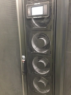
Fig 3. CCR2 Data Rack In-Row Cooling.
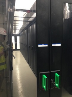
Fig 4. CCR2 Hot Aisle Data Racks.
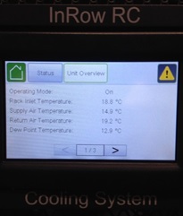
Fig 5. In-Row Cooling System Control PLC.
Field Communications Rooms (FCR) – Data from CCR2 feeds each of 37 x FCRs via a combination of copper and fibre optic connections, which also requires constant cooling provided by dedicated CRAC Units; fed by CHW from CEP. The FCRs, like CCR2, are critical to building functionality managing items such as: Building Management System (BMS), security, fire protection, nurse call, lifts, CCTV, Automated Guided Vehicles (AGVs), medical gases and the Health Integrated Network systems.
UPS Rooms – There are 3 x UPS Rooms each with 2 x CRAC Units (duty and standby).
MRI Machines – The 2 x MRI machines are hydraulically separated by plate heat exchangers with the secondary circuit pumps located in PR 6, see fig 6.
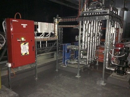
Fig 6. MRI Plate Heat Exchanger and Pump Set.
AHUs – There are approx. 82 x AHUs across 9 x Plantrooms (PR). These use the CHW to run through the coils used for air-conditioning.
Increased System Volume Issues
In normal circumstances commissioning of a piped water system would occur once all installation is complete. However, on the PCH project that was not possible due to the Client’s requirement to energise and therefore provide cooling to CCR2. The CHW feed from CEP was opened but because the initial heating load was very small, keeping the CHW flow and return permanently open would mean the return temp to CEP being around 8°C; too low. This gave a very small ∆T (7°C flow and 8°C return) and the concern was this would cause the CEP BMS to reduce the cooling required by the chillers thinking it’s not required and potentially turn them off or reduce their cooling. This would adversely affect other areas of the QEII Medical Centre, whose heating loads are at normal operating capacity.
In order to avoid this the PCH site controls the volume of CHW through; enough to provide sufficient cooling for current heating loads via the CEP Isolation Valves (IV). The design intent is to permanently keep the CEP IVs open to allow the CHW to flow from CEP around the PCH site and back again, closing the loop.
The design intent cannot be achieved until PCH sees ‘normal operating’ heating loads to avoid the return CHW being too cold; it should be around 14°C to avoid the above issue. This heating load will not be seen until all external facades are in place, the building has been completely sealed to the outside elements and all heat generating equipment has been installed like: lighting, AHU fans running etc. Only then will the AHUs be demanding sufficient CHW in order to maintain comfortable working conditions. Until this time the CEP IVs will be left in a controlled open/closed when necessary state with the decoupler loop valve left in the open position to allow what CHW has been let through to circulate round the PCH CHW system.
Periodically, when the PCH CHW temp begins to rise, the CEP flow IV is opened (operated by temp sensors that control the motorised valve) for a brief period to allow a slug of 7°C CHW through and similarly the return IV opened to allow a slug of 10 – 14°C CHW back to CEP. This procedure is fine in theory but in practice the CEP IVs are not meant to be operated at such regular intervals as they are designed to be either open or closed and not to regulate flow.
At present, because the BMS is not yet fully operational, the basement services co-ordinator has to manually set the return flow trigger temp (set at 10°C) to allow a slug of CHW through from CEP. This trigger temp is set based on the cooling load required for the equipment from across the building; which at present is very low. However, there are certain critical areas that must stay cool but have been experiencing high temps lately. These are the FCRs and UPS rooms.
The issue currently seen is caused by the following factors:
Due to a number of plantrooms having completed their commissioning they were ready to open-up to CEP via the central services risers. As they were opened the CHW system volume increased and with that the system pressure dropped. This meant that the flow rate was too low and the CHW would have gained too much heat by time it reached the FCUs (even with lagged pipes). The knock-on effect was that the FCRs and UPS rooms were struggling to keep cool as the FCUs / CRAC units were unable to provide sufficient CHW due to the reduced system pressure. An additional reason why the FCRs were getting warmer was because the building fabric is now better sealed and climate conditions are changing; getting hotter outside.
Solution
The solution is easy and in order to increase the flow rate and thus increase the system pressure the mechanical pumps need to increase their speed. Currently there is only one pump running at 40 Hz. When it is manually increased to 50 Hz (its design maximum) and if the system still requires more velocity pressure, an additional pump will be run-up to maintain this; found from the equation derived from Bernoulli’s: Pv = ½ ρ c2.
At present until the BMS is fully operational, where two pumps at a time will run simultaneously; a second pump will have to be run-up manually. This will allow commissioning works to continue; balancing of individual plantrooms and thus not hold-up subsequent integrated commissioning or the project as a whole. The fully operational BMS is around three weeks away and that is a lot of time to lose to wait for the perfect control solution. Therefore, the interim measure requires careful co-ordination of the requirement to increase pump speed matched to the increasing system volume (from opening subsequent plantrooms to CEP CHW) in order to maintain system pressure. It also requires a robust means of monitoring temp control.
Co-ordination Requirements
It was evident that from the questions I was being asked by the installation services co-ordinators, that there was no clear methodology or plan in place in which to open-up subsequent plantrooms to CEP CHW in a sufficient way that would not cause the system to ‘fall-over’. In particular, my concerns were that critical equipment reliant on a CHW supply could become damaged, costing huge sums of money to replace, such as: MRI machines, UPS and FCR equipment.
So what part did I play in co-ordinating the effort to resolve these current issues?
The thing that was most obviously about the CHW system was that there were many people involved who were working in their own little silos with little communication happening. The first thing I wanted to achieve was to establish the single point of truth and from a commissioning team perspective, understand the system and what issues we were facing. This was achieved through an initial mtg with all key players: design consultant, construction subcontractor, controls subcontractor and us the managing contractor.
The mtg was successful in a number of ways, most notably was a number of action points for the subcontractors to answer and allow us to co-ordinate accordingly thus ensuring the integrity of the system and that critical areas did not get too warm.
In practice the co-ordinated plan didn’t quite survive first contact. The plan was to open up PRs 4, 5, 6 East and 8 to CEP. The objective was to open them all but maintain the current flow rate knowing that critical equipment was stable in a ‘happy’ state. We started off by measuring the flow rate to one of the FCRs in PR 6 which was 0.375 l/s, 140% of design flow rate of 0.27 l/s. This was with 1 x pump running at 46 Hz.
We then ran up a further 2 x pumps and backed-off the first pump to match them. This was an iterative process until we got to a comfortable flow rate in PR 6. This was 86% of 0.375 l/s which equated to about 120% of design flow rate. All 3 pumps were running at 40 Hz.
We then opened-up PR 4 and went back to PR 6 to measure the % drop. We were at 81% of 0.375 l/s and content with that flow rate. All 3 pumps still at 40 Hz.
However, PRs 5 and 8 remained closed-off to CEP as I felt the condensate drains and some un-lagged pipework not being complete could cause condensation issues. Once these are complete these can be opened.
We also witnessed the CEP CHW IVs opening and shutting letting through CHW as required based on the return temp control. Therefore, we were content if the temp rises then CEP will restore it.
All pumps were still only manually controlled and would require the same above process for energising the remaining PRs to CEP.
It was found that the flow temp was slightly higer than design and should FCRs, CCR2 or MRI temp increase then we should first look at this. Currently with the mixing occurring through the decoupler we are seeing a flow temp of around 10 – 11 °C. This is more likely the reason why areas are getting too warm rather than pressure drops or reduced flow rates.
The position we want to be in is have PR 1 flushed and opened to CEP. This being the index run throughout the building means we can set the pumps to monitor the differential pressure at that point. This is so that no matter if we open-up additional PRs (increasing system volume) or if we close-off PRs (reducing system volume and thus potentially causing a pressure build-up in a closed head scenario) then the controls can adjust accordingly in dynamic fashion and remain stable.
What did I learn?
- If you are at the point where speaking to different parties gives you the feeling that the right hand isn’t talking to the left then you need to set up a mtg sit everyone down and systematically run through what’s what, where you are currently at and where you want to get to.
- Old school still works. I’m referring to the simple but very effective method of printing off A0 dwgs and physically highlighting the pipe runs using a different colour to distinguish its status: flushed and cleaned, opened to CEP CHW, proportionally balanced etc. It provides a dynamic way of statusing the progress of a system when dealing with a complex building with nine plantrooms over nine floors.
- Condensation is a real concern as proved by a number of valves not being lagged before CEP CHW connection as shown in figs 7 and 8.
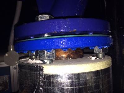
Fig 7. Condensation Formed Drops on Valves.
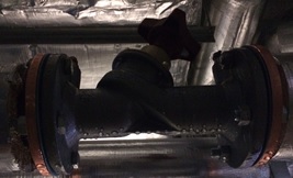
Fig 8. Condensation Formed Drops on Valves.
4. A slightly annoying learning point is that no matter how many repeated verbal and written communications are made, subcontractors still ‘do their own thing’. An example of this was where the condensate drains not being correctly installed before the AHU CHW coil IVs were opened, causing the inevitable ‘sweating’ (condensation) to drip off the coil into the condensate collection tray through the drain pipe then onto the plantroom floor. The subcontractor, Fredon, said the spill on the floor was from when the engineer replaced the clear plastic section in the drain pipe to copper, as per fig 9. But I wonder how much trouble it would have been to use a receptacle or even just tissue paper to mitigate getting the floor wet? And, how do they explain opening up to the coil with the obviously missing section of pipe that should continue to the tundish in fig 10? This leads on to valuation payment claims from the subcontractor being reduced.

Fig 9. Condensate Drain Replacement.
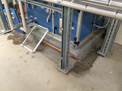
Fig 10. Spot the Obvious Issue?
5. Although I am a member of the commissioning team, I have come to realise that you can never truly get away from construction/installation issues. Sequentially, the installation must be complete prior to commissioning activity so inevitably it falls to us to drive construction completion in order to stay on track with our commissioning programme.
In Other News
The British Defence Advisor to Australia, Commodore R L Powell OBE MA MSc RN, was visiting Perth and requested the presence of those on military exchange programmes.
There were only three of us Brits meeting the 1-Star, a RN Officer working at Garden Island (a nearby Naval Base), a SBS Warrant Officer working as the UK LO to the Australian Special Forces based just up the road at Campbell Barracks, and then myself.
The visit was pretty low-key with the Attaché just asking us how we were all getting along on our respective programmes and if we had any issues in moving out here. He then spoke a bit about ongoing projects from a relationship with Australia perspective. This was all good background info and sounded quite interesting, especially the fact his post out here is a 4 year tenure – nice if you can get it, oh and have promoted to Brigadier – no biggy!
A Near Miss
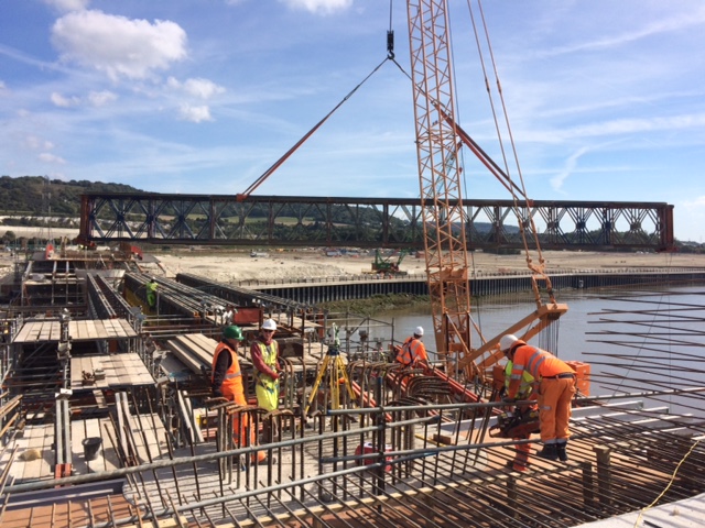
Part of our falsework system incorporates 7No, 21tn, 30m trusses. These are assemble on the ground and lifted into place.
On Tuesday one of these trusses fell over during construction and landed at the feet of one of the lads. The panel that fell weighs 380kg. This is the sixth truss built on site, no previous concerns had been raised.
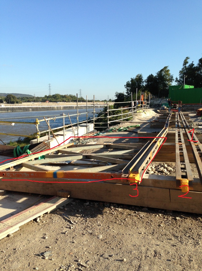
The highlighted panel was vertical. Bottom cords 1 & 2 are in the correct position, 3 has rotated with the panel. This panel had no lateral bracing.
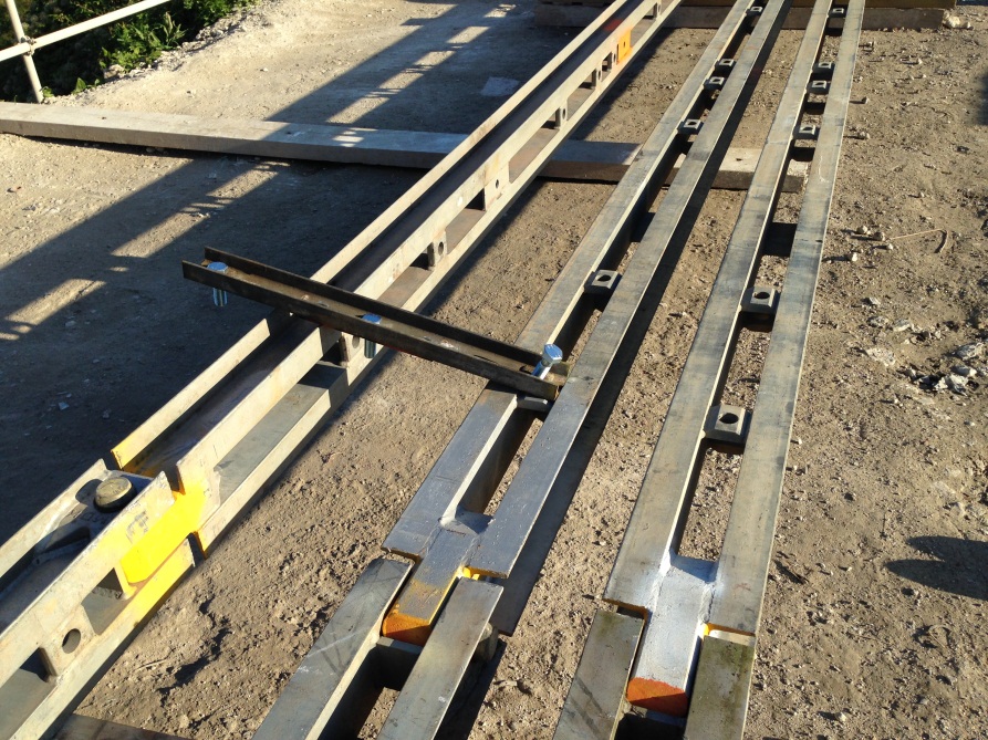
The cross bracing has pulled out of it’s alignment. NB, this was not bolted as the cords are left free to creep through construction. The construction method was instructed by the supplier.
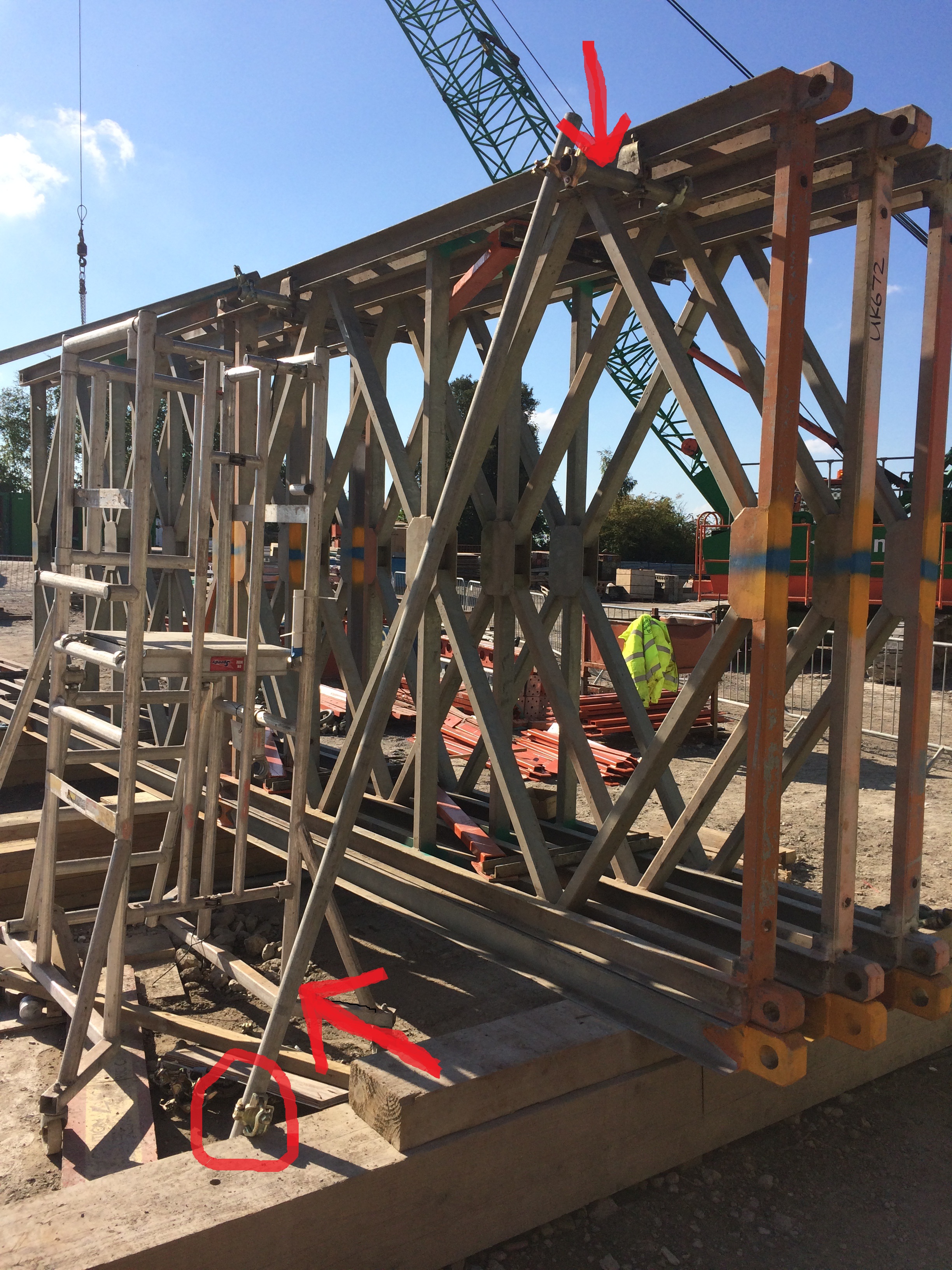
The revised construction method includes ‘tube and fit’ bracing.

The bracing is also tied back to the hand rail which has been increase to deal with greater loads.
Installation of these trusses sits on the crit path so no time was wasted in assessing, reviewing and modifying the construction. This process was thorough and the new mitigations seem to be appropriate and full proof with regards to a repeat of this situation.
A happy truss!!!
A link for the E&Ms (Fran, you should suggest this for your hospital!!!)
Stormy Weather
Quite an eclectic blog, due to the range of ‘stuff’ going on at the moment…
Safety
My Chiller plant is progressing well with CMU going up, albeit at a fairly modest rate, and MEP being hung. One of the over-arching requirements of the project engineers is to keep an eye on the safety aspects of the work. The CMU walls are braced as they are erected until they are tied in to the structure. This occurs when the top bond beam is in place and secured to the roof joists. As the walls get higher so do the braces. I hadn’t seen any braces being moved so I thought I would take the charts, which were discussed at the prep meeting, on my site walk and have a look. For some reason the braces hadn’t been moved, a fact which I highlighted through the principal contractors’ safety chain. They were fairly swift in rectifying the issue with minimal fuss. Below is a copy of the chart which is in the manufacturers product data, submitted as part of the prep meeting. I measured the brace run as 10’ but the wall had progressed to c. 28’ in height.
CMU bracing chart
Changes
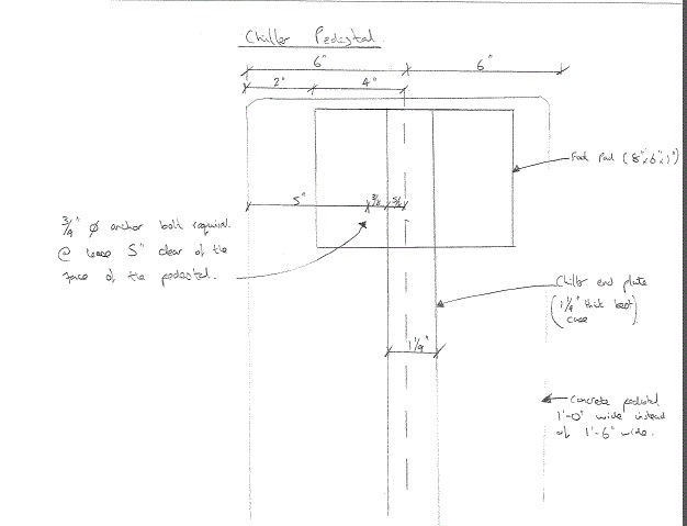
I am drafting a Basic Change Document (BCD) for some concrete pedestals onto which a large piece of mechanical equipment will sit. The contract documents call for a wall of 12” width, which is what the PC has built. The mechanical equipment features in other areas of the programme, except in those projects the support pedestals are 18” wide…
Not sure why theres so much white space…
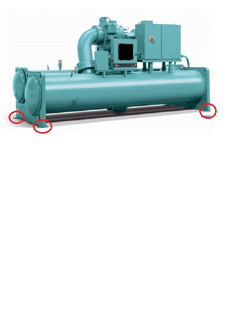
The picture above shows the mechanical equipment with the anchorage points circled. These have ¾” anchor bolts drilled through them and epoxied into the concrete pedestal to a depth of 4’. An RFI was sent to the Designer of Record (DOR) who confirmed that there had been a design bust and sent a bulletin updating the contract drawings. Since the PC didn’t want to demo the pedestals the DOR also sent out an option to anchor the equipment to the thinner pedestals. This option required the mechanical manufacturer to add extra anchorage points to their equipment, along with some restrictions on anchorage distances. I didn’t think anything of it at this point; the PC was happy that they were no longer required to demo the pedestals and could engage with the manufacturer to arrange for the fabrication of additional anchor points and USACE was happy because the change was fairly minimal. I then sketched out the dimensions (below).
Now, it is easy at this point to berate the DOR however it should, in fairness, be noted that the mechanical equipment in question had not been firmly agreed by the promoter at this point and hence some of the dimensions were ‘a bit fuzzy.’ So. Plan A it is then; demolish the pedestals.
I will write the BCD which is essentially a Request for Proposal (RFP). It will go to the PC who will send us their proposal for how much they think the change of scope will cost. Independently we will produce a Government Estimate (IGE) which will be followed by negotiations to agree a ‘fair and reasonable’ price for the work. The contract will then be adjusted to incorporate the change and reflect the increased project cost. The last BCD I wrote produced a $200k debit, so I’m hoping to still be in the black after this change. Provisionally $28k has been set aside! Seems a lot but I’m doing the IGE shortly so we’ll see.
As Builts
Another area where I’ve been addressing issues is with regard to red line drawings and as builts. The focus was bought to this area due to a drainage run which was installed at the wrong elevation. When the adjacent project ‘found’ the drainage run with their plant, somewhat unexpectedly, we asked the PC for their red lines, which took about 3 days to get a hold of. This set alarm bells ringing – it became clear that, in some areas at least, they were not properly being maintained. I was tasked to write a letter and attach an agreed Memorandum of Understanding (MoU) relating to as builts, highlighting the contractual requirements for the PC to maintain 2 sets of red line drawings, hard copy, which should be inspected weekly and submitted monthly with the pay application. (Note: A letter is a contractual ‘lever’ USACE uses because a formal letter obliges the PC to respond with positive action or a letter of explanation)
I wanted to negate too much to-ing and fro-ing between USACE and the PC, so I approached the MoU in an open manner, inviting the PC to meet up and discuss the issue; the inability of the PC to access that one red line when requested led to a lot of background information. It transpired that a verbal agreement had been made between a USACE employee (who typically was responsible for checking the red line drawings) and the PC such that the requirement for hard copy red lines was ignored and all red lines were electronically kept up to date. Since each PC site engineer has a field iPad which can access the drawings on site this seems sensible, however the arrangement was not communicated to USACE. I have incorporated this into the new MoU to do just that. It was also negotiated that USACE receives the weekly update onto our shared drives (using an external hard drive to do a data dump). This includes hyperlinks to all RFIs, mods, changes, specs etc and is a huge improvement on what USACE currently has and will make it much simpler to keep tabs on how up to date the PC is keeping their red lines. This should prevent a recurrence of the incident which kicked off issue in the first place. I have been asked to give a presentation to the rest of the project delivery team highlighting what the PC is contractually required to do with regards to red line drawings and propose the mechanism to keep tabs on their compliance with the MoU.
RFIs
We’ve ran out! Because the job is a design bid build RFIs go back to the designer of record, something I’ve noted before causes a lot of frustration to the PC because they are accustomed to design-build jobs and have a fairly good design capability in house. Anyhow, there was a set number of RFIs negotiated into the contract price with the designer, with design busts, errors and omissions being answered for free. At last count there was just shy of 1000 RFIs since the start of the project (Apr 14) and there is no money on the contract to pay the designer to answer any more. We can’t stop the RFIs because assumptions made by the contractor mean he becomes liable which is a false transfer of the risk because he is, likely, not indemnified for design faults or errors. So, USACE ‘tech assist’ which is already a busy department is now being consulted on RFIs. This is less than ideal because 1, in my opinion, you are not well suited to answer design / clarification questions if you haven’t got the background of actually designing the thing in the first place; 2 USACE is in danger of picking up some of the risk it has already paid to transfer by having somebody else design the project and 3 because it takes ages!
In other news
This…