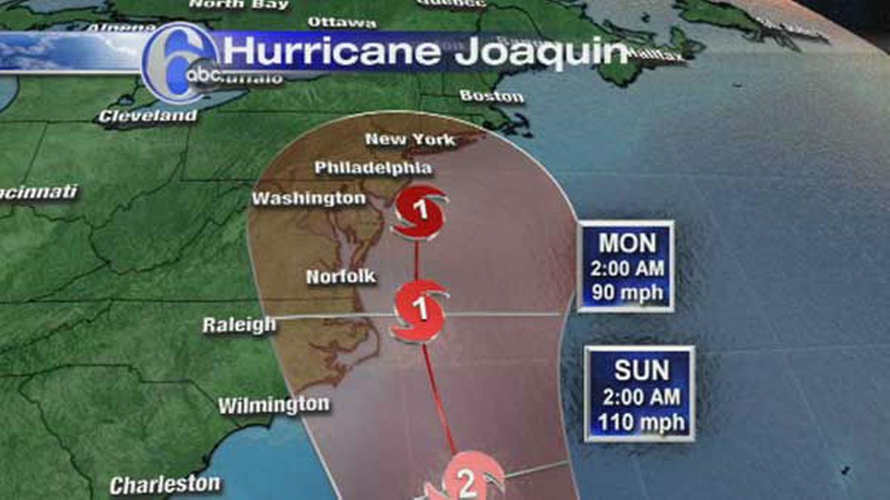
Stormy Weather
Quite an eclectic blog, due to the range of ‘stuff’ going on at the moment…
Safety
My Chiller plant is progressing well with CMU going up, albeit at a fairly modest rate, and MEP being hung. One of the over-arching requirements of the project engineers is to keep an eye on the safety aspects of the work. The CMU walls are braced as they are erected until they are tied in to the structure. This occurs when the top bond beam is in place and secured to the roof joists. As the walls get higher so do the braces. I hadn’t seen any braces being moved so I thought I would take the charts, which were discussed at the prep meeting, on my site walk and have a look. For some reason the braces hadn’t been moved, a fact which I highlighted through the principal contractors’ safety chain. They were fairly swift in rectifying the issue with minimal fuss. Below is a copy of the chart which is in the manufacturers product data, submitted as part of the prep meeting. I measured the brace run as 10’ but the wall had progressed to c. 28’ in height.
CMU bracing chart
Changes
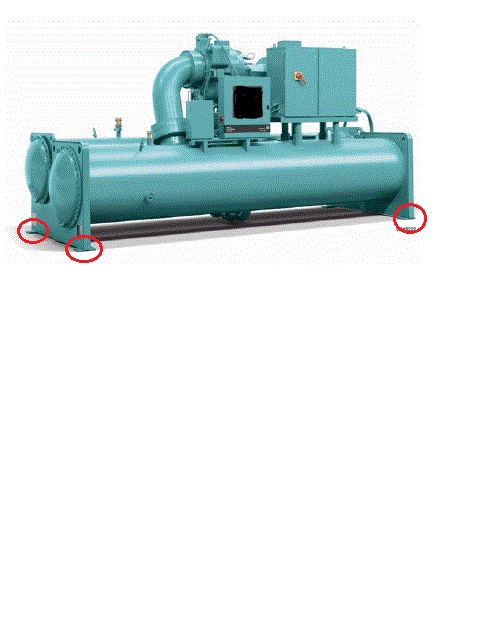
I am drafting a Basic Change Document (BCD) for some concrete pedestals onto which a large piece of mechanical equipment will sit. The contract documents call for a wall of 12” width, which is what the PC has built. The mechanical equipment features in other areas of the programme, except in those projects the support pedestals are 18” wide…
Not sure why theres so much white space…
The picture above shows the mechanical equipment with the anchorage points circled. These have ¾” anchor bolts drilled through them and epoxied into the concrete pedestal to a depth of 4’. An RFI was sent to the Designer of Record (DOR) who confirmed that there had been a design bust and sent a bulletin updating the contract drawings. Since the PC didn’t want to demo the pedestals the DOR also sent out an option to anchor the equipment to the thinner pedestals. This option required the mechanical manufacturer to add extra anchorage points to their equipment, along with some restrictions on anchorage distances. I didn’t think anything of it at this point; the PC was happy that they were no longer required to demo the pedestals and could engage with the manufacturer to arrange for the fabrication of additional anchor points and USACE was happy because the change was fairly minimal. I then sketched out the dimensions (below).
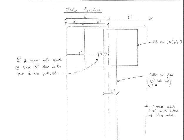
Now, it is easy at this point to berate the DOR however it should, in fairness, be noted that the mechanical equipment in question had not been firmly agreed by the promoter at this point and hence some of the dimensions were ‘a bit fuzzy.’ So. Plan A it is then; demolish the pedestals.
I will write the BCD which is essentially a Request for Proposal (RFP). It will go to the PC who will send us their proposal for how much they think the change of scope will cost. Independently we will produce a Government Estimate (IGE) which will be followed by negotiations to agree a ‘fair and reasonable’ price for the work. The contract will then be adjusted to incorporate the change and reflect the increased project cost. The last BCD I wrote produced a $200k debit, so I’m hoping to still be in the black after this change. Provisionally $28k has been set aside! Seems a lot but I’m doing the IGE shortly so we’ll see.
As Builts
Another area where I’ve been addressing issues is with regard to red line drawings and as builts. The focus was bought to this area due to a drainage run which was installed at the wrong elevation. When the adjacent project ‘found’ the drainage run with their plant, somewhat unexpectedly, we asked the PC for their red lines, which took about 3 days to get a hold of. This set alarm bells ringing – it became clear that, in some areas at least, they were not properly being maintained. I was tasked to write a letter and attach an agreed Memorandum of Understanding (MoU) relating to as builts, highlighting the contractual requirements for the PC to maintain 2 sets of red line drawings, hard copy, which should be inspected weekly and submitted monthly with the pay application. (Note: A letter is a contractual ‘lever’ USACE uses because a formal letter obliges the PC to respond with positive action or a letter of explanation)
I wanted to negate too much to-ing and fro-ing between USACE and the PC, so I approached the MoU in an open manner, inviting the PC to meet up and discuss the issue; the inability of the PC to access that one red line when requested led to a lot of background information. It transpired that a verbal agreement had been made between a USACE employee (who typically was responsible for checking the red line drawings) and the PC such that the requirement for hard copy red lines was ignored and all red lines were electronically kept up to date. Since each PC site engineer has a field iPad which can access the drawings on site this seems sensible, however the arrangement was not communicated to USACE. I have incorporated this into the new MoU to do just that. It was also negotiated that USACE receives the weekly update onto our shared drives (using an external hard drive to do a data dump). This includes hyperlinks to all RFIs, mods, changes, specs etc and is a huge improvement on what USACE currently has and will make it much simpler to keep tabs on how up to date the PC is keeping their red lines. This should prevent a recurrence of the incident which kicked off issue in the first place. I have been asked to give a presentation to the rest of the project delivery team highlighting what the PC is contractually required to do with regards to red line drawings and propose the mechanism to keep tabs on their compliance with the MoU.
RFIs
We’ve ran out! Because the job is a design bid build RFIs go back to the designer of record, something I’ve noted before causes a lot of frustration to the PC because they are accustomed to design-build jobs and have a fairly good design capability in house. Anyhow, there was a set number of RFIs negotiated into the contract price with the designer, with design busts, errors and omissions being answered for free. At last count there was just shy of 1000 RFIs since the start of the project (Apr 14) and there is no money on the contract to pay the designer to answer any more. We can’t stop the RFIs because assumptions made by the contractor mean he becomes liable which is a false transfer of the risk because he is, likely, not indemnified for design faults or errors. So, USACE ‘tech assist’ which is already a busy department is now being consulted on RFIs. This is less than ideal because 1, in my opinion, you are not well suited to answer design / clarification questions if you haven’t got the background of actually designing the thing in the first place; 2 USACE is in danger of picking up some of the risk it has already paid to transfer by having somebody else design the project and 3 because it takes ages!
In other news
This…

Brad,
Can you not push the ‘design bust’ RFIs back onto the DOR and take them off your billing? It probably wouldn’t solve the situation entirely but you would then be able to pick and choose which RFIs to send to the DOR and which to Tech Assist based on the potential risk and therefore still be able to hold the DOR to account on the important stuff?
Oh, and the views at Shennandoah should be good this weekend…
Hey Henry – Yes, design busts, omissions and inaccuracies can be pushed back at no cost. These are sifted through our RFI process and this is what is happening at present.
Where there is ambiguity or if the PC requires clarification due to something that occurs on site (ie not necessarily a design bust) then no. An example would be anchor bolts at the base of one of my chiller plant columns, The PC installed them in the wrong alignment. Rather than strip a large portion of the structure it was proposed to drill and epoxy the remaining 2 of 6 bolts into the correct configuration. This was an engineered solution which required verification. This could be done by USACE, the PC or the DOR. At the time we hadn’t ran out of RFIs so the DOR did it, thus retaining the risk for the design, however now we would either have to pay (again) for them to retain the risk or accept the risk migrating elsewhere. Its less a matter of importance, more of who is best suited to deal with the risk. At present, unfortunately, i think that the DOR is best suited to deal with design clarification however we will be required to pay for it.
So in short, you are exactly correct! It won’t make the issue go away and yes, in some cases we can still get stuff for free.
PS – we have cancelled the trip. I can be miserable and see bugger all out of my own windows as opposed to someone elses! Plus we got our money back due to extenuating circumstances. FTW!
I don’t really see why you would push anything to USACE. Surely the simple response to erroneous installation is to offer the contractor the options to remove, make good and do agsin correctly or pay the DOR to check and forward to you the revision. After that any information required is eiher on the drawings, in the spec or is an ommission?