Two Fifty One – Concrete continuity
Two Fifty One – Concrete continuity
RC Detailing.
By way of background, Two Fifty One has two levels of in-situ basement followed by 40 storeys of precast concrete to form the tower superstructure. The lateral stability is provided by shear walls which form a perimeter around the lift and stair shafts.
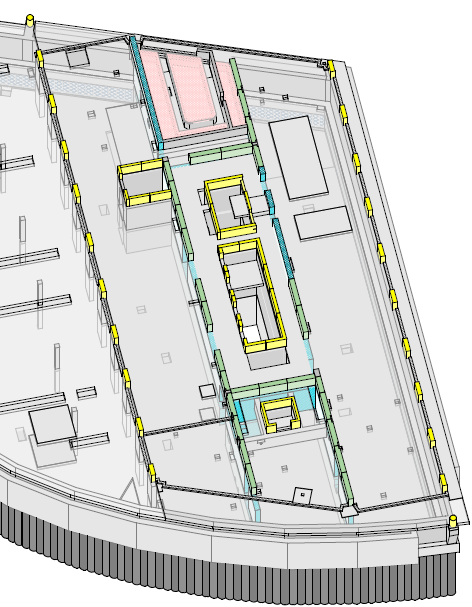
Substructure – The green walls represent the shear walls in the tower. Inner yellow walls demote lift pit and stairwell.
The slab to shear wall connections in the tower basement floors have been designed using kwikastrip. These are pre-bent bars that sit within a case and then are bent on site at a later date.

Kwikastrip pull-out bars
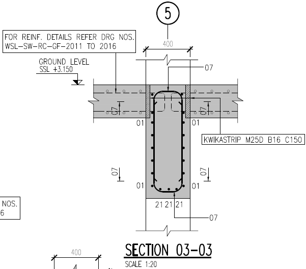
Kwikastrip used to form wall to slab connection joint.
The more typical method would be to run slab steel through the walls as shown in the figure from the IStructE Standard Method of Detailing Structural Concrete.

The reason is to enable the walls to be poured in higher strength concrete than the slabs. This is because the walls carry the loads down the building to the raft foundation to the piles below. From a buildability perspective it means the walls need to be cast to the structural slab level (ssl) rather than to the slab soffit. Other than the fact the falsework had initially been designed to soffit level this not a problem.
One of the key considerations of using pull out/continuity reinforcement bars is the rebending of the reinforcement.
Bending reinforcement on site presents the risk of overstressing the steel by bending it to too tight a radius thereby weakening it.
The bar diameter of kwikastrip is limited to 16mm and a bar bending tool should be used to rebend the reinforcement. The IStructE Standard Method of Detailing Structural Concrete states that “where it can be shown that the bars are sufficiently ductile (kwikastrip uses Class B steel so is acceptable) bars not exceeding 12mm size may be rebent provided care is taken not to reduce the mandrel size (radius of bend) below four times the bar size”. The same is also be true for 16mm steel at seven times the bar diameter.
This requirement needs close quality control to ensure bars are rebent correctly. The walls use both 12mm and 16mm steel kwikastrip making it even more important not to confuse the bar diameter with bar bending tool (or the strips themselves). Halfen (kwikastrip supplier) state: “the straightening tool is a steel tube with a specially shaped end and an internal diameter only slightly greater than the diameter of the bar to be straightened” hence strict quality control is needed to firstly use the tool (rather than any old scaffold tube) and secondly use the correct tool.
Other considerations include:
Increased time to fix the items in (fiddly).
Procurement ordering time – the items need to be ordered specifically, not called off from reinforcement schedules which requires lead time and storage.
Increased cost (circa 8k for one level of slab) compared to extending the reinforcement bars a short distance. Cost of standard stock steel per tonne is less than equivalent of weight of kwikastrip.
The structural requirement to maintain concrete continuity has overridden the practical installation disadvantages and that is how it will be built.
Other points
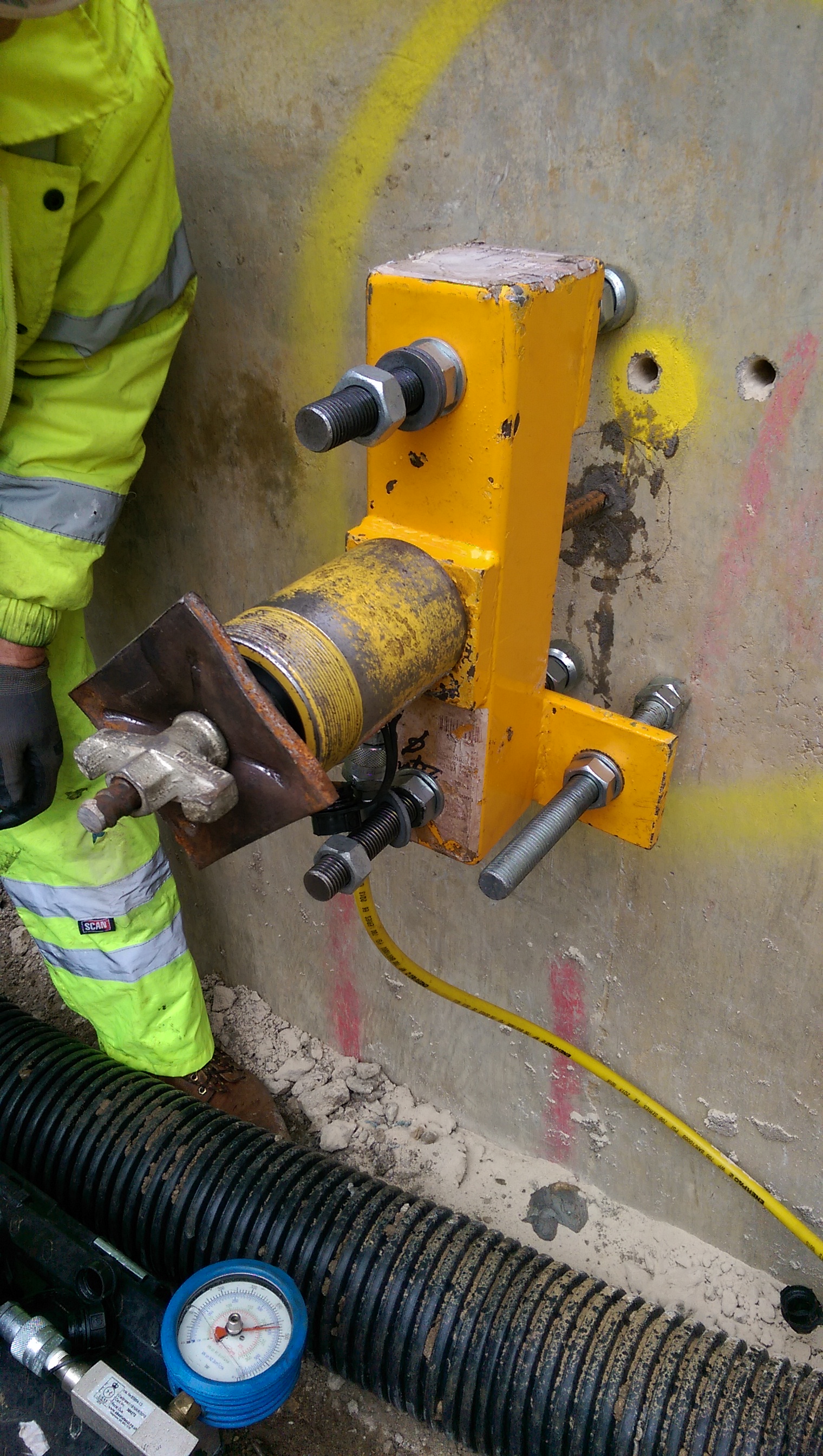
Pull out tests. We want to use an existing retaining wall to resin in dywidag bars to connect a one sided shutter to form a new retaining wall. We will be using Peri shutters with pre-set tie bar positions. The pull out tests showed no movement at 150kN, other than a bit of feet penetration into some old plaster on the wall. At 150kN there was a crack sound as the resin slightly debonded from the concrete and at 200kN there was evidence of some a cone failure (see circular crack around bar). The aim was to confirm a 90kN force would not be exceeded which the tests proved was the case. Interestingly the critical factor in pouring the walls will now be the pressure on the formwork soldiers and walers, rather than tie force. Therefore the rate of rise will be controlled especially because we have retarders which increase the pressure exerted on the formwork.
Propping scheme. The view below shows the site with the props spanning over the basement. In order to remove the props the basement level 2 slab must be cast halfway between them. This was creating a bit of a pour sequence issue as clearly the props are not angled in a way which suits the foundation layout!
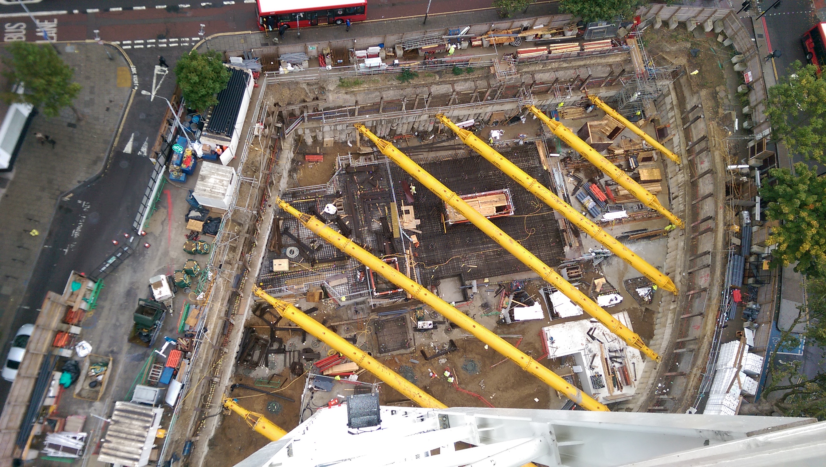
Two Fifty One from our first of 4 tower cranes.

On the Kwika strip – it does look like a fairly expensive soslitiion; I could see short bars with connectors on either end being just as bad – but probably cheaper. I’m always perplexed at these rebend warnings; firsly the minimum bend for small dia bars is about 2 diameters. secondly strainilinbg steel eventually has a strain hardening – so why the worry at all?
On the propping geometry – it’s communication between subcontractors – what looks like a symmetrical solution for one is a nightmare for the other. Looking at the geometry on does wonder why there aren’t two knee braces and props that align with the structure thereafter
John, thanks for the comments. Regarding the steel piece, I am sure you are right about the bending not being an issue but being cautious with the sometimes over zealous steel fixers is likely to result in a sensible balance between going beyond a hardening limit and a workable solution.
The propping scheme in my mind is a mistake or an oversight by us. The only slight advantage of this simple solution is that the straight (top of the photo) section is well braced. This is near to the northern line tunnel which has movement limits on it. We have seen about 8mm of deflection between props where 15mm is allowed, so perhaps greater spacing would have worked.
I think the simple solution that we have was easy to install but made removal to erect walls and columns a bit of a sequencing nightmare.
We use pull-out bars on all of our core-floor connectors due to the construction method of the cores. Due to the way slipform works we’re unable to have starter bars cast in. The wall is too thin to allow for bars to be drilled and fixed using resin. Fixing loads of individual bars with full strength couplers would take too long and they have a tendancy to be dragged up by the formwork as it moves past. So kwickastrip really is the only (although expensive) solution.
Rebent bars are a useful solution but the cautions are: They have limited bar size and a near fixed spacing which can result in area of steel challenges; the act of rebending must not leave a tight radius bend or there may be localised failure of the concrete due to stress concentraion on the inside of the bend, and; although the bars will work harden this results in loss of ductility so any designed redistribution or seismic tolerance may be impacted. Finally, of course, they are expensive. And after all that, they remain a useful tool, particularly in slip form works.