Archive
Hospital Pass
Part of the role of USACE, as the client’s representative, is to conduct design reviews for design-bid-build contracts (read traditional contracts). These are done at 35, 65 and 95% with comments provided back to the project manager and design team, be it in house or a consultant, through an online system (Dr Checks). The designs are reviewed by us at construction division as well as the design division and are passed out to the clients and facilities managers, probably amongst others.
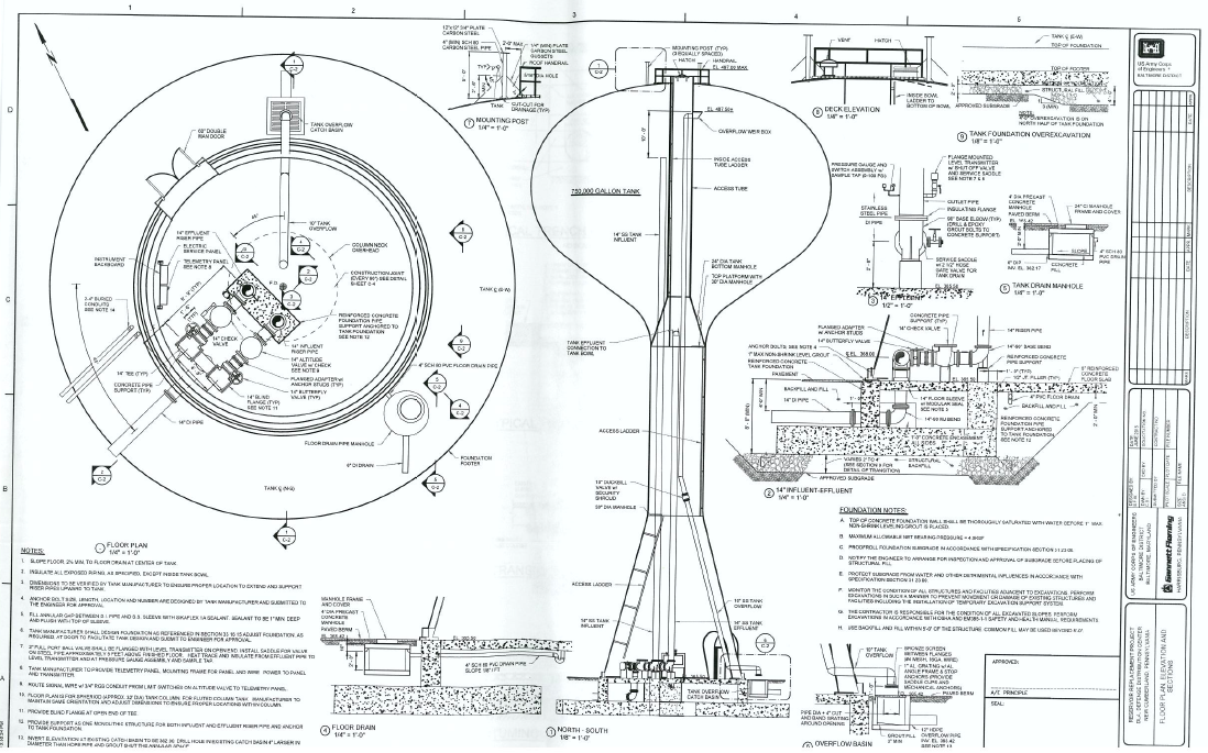
A couple of weeks ago, due to staff being on leave, I was given one of these to look at the pumps, seemingly alone. Having no idea what to do I browsed the drawings to work out what the issues might be. The project is a new 750,000 U.S. gallon water tower for domestic water and as a fire supply so my pavlovian response was Bernoullis!
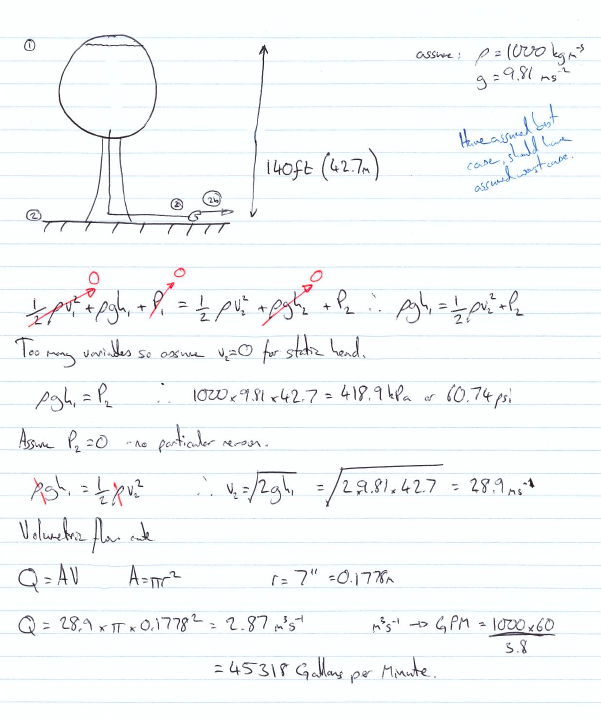
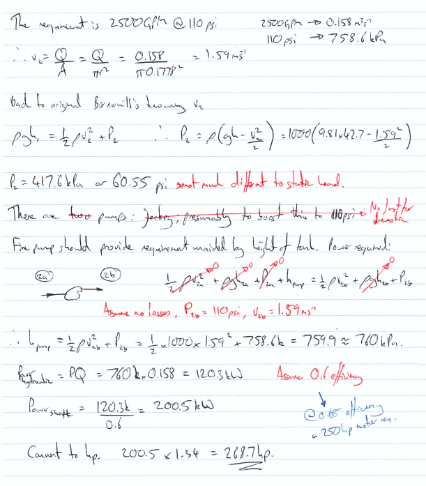
After checking the answer it seemed about right although there were no accompanying design calculations to the contract and drawings so I chalked up my first comment. The rest of the checking passed with less excitement. There were a few clauses that had been missed from the contract, some ill thought out processes and demolition elements missing from the drawings. It seems a common theme though that construction division give the most comments, usually about build ability and, as discussed in the past, what is actually existing at the site.
So what have I learnt:
Hopefully I’ve done Bernoulli’s right; simplify the problem and sketches work.
Designers, it appears, live in a magic construction dreamland and it is always the same build ability issues that are picked up. By using traditional contracts USACE does assume a lot off risk and pays handsomely for the privilege if elements aren’t caught by the construction team prior to tendering. Having recently moved into dreamland, albeit part time at present, the fine detail is easy to forget.
And as ever, time spent on recce…
Oz PCH – Electromagnetic Compatibility Concerns.
Introduction
Within Fredon’s (mechanical installation subcontractor) scope of works, one element is the mech-elec installation works associated with Variable Speed Drives (VSDs) site-wide. After a quality review, conducted by NDY (design consultants), of the standard of installation of completed works, a number of defects were found that were felt didn’t comply in accordance with the mechanical quality specification; of note was the VSD controller cable installation. These were communicated to JHG via a Consultant’s Advice Notice (CAN), which is routine practice.
Fredon did nothing to rectify the defects relating to the VSD cable and so JHG issued an Event Notification. This consisted of a Non-Compliance Report (NCR), raised on JHG’s internal quality management system. This has significant commercial implications for the subcontractor if not resolved in a timely manner.
Issue
The NCR stated that Fredon had not complied with the mechanical specification as the current installation did not include Electromagnetic Compatibility (EMC) glands amongst other issues. The NCR also stated that any installation works completed to-date must be removed and replaced with a fully compliant installation as per the project specification.
Fredon responded as required and provided explanation, aided by technical analysis from their electrical works subcontractor, Electromaster, for their reasoning behind their actions.
They confirmed that whilst they had installed an alternative to the specification, in all cases they meet the fundamental design intent, and in some cases have improved on it.
After a number of meetings NDY stated that whilst it was noted that some aspects of the installation may not comply with the literal wording of the specification, if Fredon were to demonstrate that the installation achieved the technical intent and complied with all associated relevant Standards, then it could be possible to consider the alternative, particularly that the manufacturer’s recommendations had been met.
Technical Background
Fredon and Electromaster put together a technical response on the issues raised in the NCR, in particular, for the EMC gland issue and stated that what they have installed also complies with Australian Standard AS 61800.3:2005 Adjustable speed electrical power drive systems – EMC requirements and specific test methods.
Why is electromagnetic shielding required?
In simple terms, all electrical equipment that has current running through it produces an electromagnetic field (EMF). This field requires shielding in order so that a build-up from multiple fields don’t interfere with other sensitive electrical equipment, especially the likes of those used for recording patient’s vital stats; in a hospital this accounts for a very large portion of electrical equipment and so electromagnetic shielding is vitally important. In addition, on certain equipment like VSDs where an inverter chops up the sinusoidal waveform, inverts it and splices it back together (through switching transistors on and off at a fast rate), this creates Radio Frequency (RF) energy which can be radiated and then coupled onto other equipment’s control and supply cables through either capacitive or inductive means. It can also be conducted to other equipment through a common impedance path such as an earth connection. So, it is even more important to shield cables that come out of VSDs.
How do we shield against it?
In this case we are talking about the motor power cable that runs from the VSD to a motor isolator switch and then to the motor itself. The mains electrical power cable to the VSD, although still carrying current, is not required to be shielded as it will be at 50 Hz and thus the same as other equipment and so doesn’t pose significant interference.
To shield cables a wire braided screen is used to surround the inner core conductor. This shielding impedes both the escape of any signal from the conductor and also prevents signals from being added to the core conductor – thus completely isolating the cable (see fig 1).
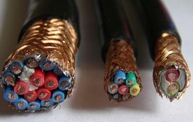
Figure 1. Typical Cable Wire Braided Shielding.
Issue Continued…
Electromaster included the manufacturer’s data sheet for the particular VSD supplied by Schneider which is used site wide; the ATV212W. They highlighted the relevant parts that confirm their installation complies with the standards. So, if NDY are content with this as mentioned then problem solved right? Not quite…
On closer inspection of Fredon and Electromaster’s technical response they highlighted the wrong VSD model and marked-up the installation guide for the ATV212H not the as-installed ATV212W.
The technical prove information was on page 52 of the installation guide, at the bottom of which it describes the ATV212W model and on the following page it clearly describes the correct cable arrangement and use of the EMC plate. Figure 2 shows the ATV212W and specifically states that the cable gland must be ordered separately as it’s not supplied with the VSD.
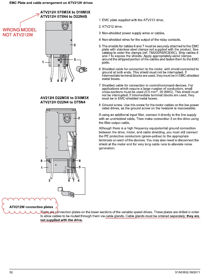
Figure 2. Manufacturer’s Installation Guide p.52.
Figure 3 shows the next page and highlights the need for a metal EMC gland and explains the mounting and connection required to correctly shield the cable and drive.
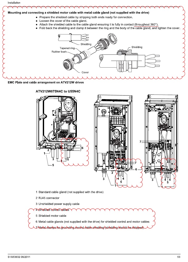
Figure 3. Manufacturer’s Installation Guide p.53.
Why was it installed incorrectly?
My view is that Electromaster have installed the VSD cables based on a combination of factors in order to save both installation time, which equals a labour cost saving, and capital costs. These are:
- Carrying out installations as per what they have previously done on other projects;
- Using standard plastic glands as these are significantly cheaper than metal EMC glands;
- Saving on labour time (approx. half) and thus reducing cost, by installing plastic glands over EMC glands, and;
- Possibly not having even read the design specification.
What is missing from their technical explanation of what they have installed is the actual termination of the motor cable into the VSD. An on-site inspection proved that they had indeed connected to the metal back plate in the VSD housing which is separately earthed, but the connection to the earth bolt was achieved by pulling the wire braided shielding round to one side and twisting it together to form what is referred to as a ‘pig-tail’ (bunched-up strands) and attached to the earth bolt (see fig 4).
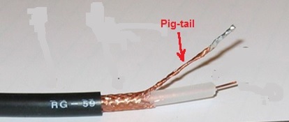
Figure 4. Cable Shielding Pig-tail – Bad Practice.
Figures 5 and 6 show the actual VSD installed by Schneider but wired by Electromaster. It can be seen in figure 6 the use of a standard plastic gland opposed to a metal EMC gland and also the shielding twisted into a pig-tail (heat shrinked in a green sheath) and connected to the ECM plate (earth). If the installation was left as it is then the pig-tail termination of the screening would mean that RF leakage could potentially escape through all the plastic glands seen in the bottom of the drive.
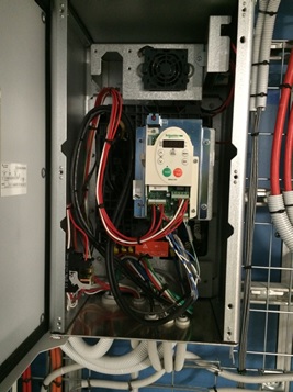
Figure 5. Schneider’s Installed VSD.
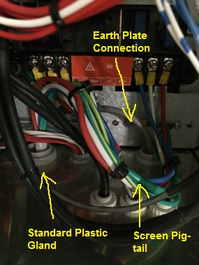
Figure 6. Electromaster’s Wiring of VSD Motor Cable.
The issue with what Electromaster has done is they haven’t completely screened the cable through 360 º, like the examples in figures 7 and 8 show.
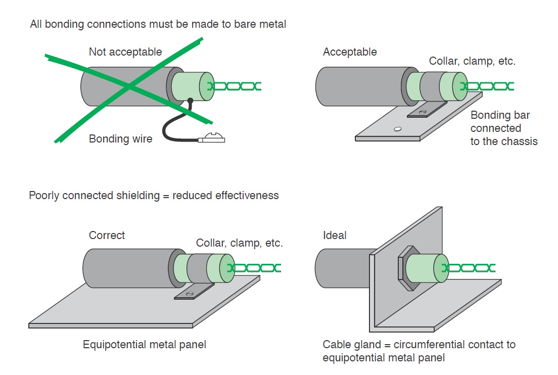
Figure 7. Schneider Electric Earth Connection of Shielding.
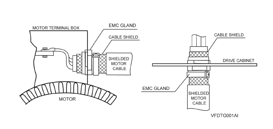
Figure 8. Power Electronics Earth Connection of Shielding.
The reason the lack of 360 º screening is such an issue is that when dealing with high-frequency electromagnetic radiation from an Alternating Current (AC) source it becomes distributed within the conductor where the current density is largest, near the surface of the conductor, and is known as the ‘skin effect’. The electric current flows mainly at the skin of the conductor which causes the effective resistance of the conductor to increase at higher frequencies. Therefore, RF leakage from any unshielded portion of cable can be quite high.
A quick Google search also reveals that pig-tail terminations for cable shielding is a big ‘no-no’. Even if the pig-tailed termination is inside a metal housed VSD (mini faraday cage) then technically the RF can’t escape as long as a metal gland is used. However, Electromaster used plastic glands and so this presents a clear path for any RF leakage.
The Design Specification Intent
The method behind using a metal EMC gland with a metal plate/VSD housing is that the VSD housing acts like a mini faraday cage with a separate earth cable running to ground. Where the cable enters the VSD it is secured in place by the EMC gland with the cable shielding pulled back on itself and the gland clamped around it making a 360º connection to both the shielding and the VSD housing.
The design specification explicitly says that:
Terminate screened power cables at each end in EMC glands to ensure circumferential connection of the screen to earth. Earth the screens of thermistor sensor and motor lockout cables at the converter cabinet utilising metal cable clamps for each cable fastened to an earth bar installed within the cabinet for the purpose or with EMC glands secured to an earthed gland plate externally to the cabinet, as specified by the manufacturer.
Motor isolators shall be 4-pole, key lockable mounted in a die cast alloy enclosure. The isolators shall switch the motor power and control circuits simultaneously. Cable entries shall be fitted with EMC cable glands and earth bushes suitable for the cable types connected. The earth bushes for each circuit shall be connected together with 6 mm2 cable to maintain continuity of screening of the power and control cables.
Resolution and Possible Fixes
One possible solution could have been to swap the plastic glands for metal ones as this could theoretically be adequate. However, Electromaster and Fredon would need to back-up this installation with technical proof of this which may be difficult as all reports on ‘best EMC installation practice for VSD’ state that the use of pig-tails is prohibited.
“A screened cable gland suitably designed and sized for the screened cable type used should be fitted at the motor end. Do not wind the screen into a “pigtail” and terminate under the earth terminal within the motor terminal box. Terminate the earth conductor(s) to the motor earth terminal(s) located inside the motor terminal box. When installing the SD700 directly on the wall (no additional enclosure) a screened cable gland suitably designed and sized for the screened cable type used should be fitted at the SD700 gland plate. Do not wind the screen into a “pigtail” and terminate under the earth terminal within the SD700 terminal box. Terminate the earth conductor(s) to theSD700 earth terminal(s) located inside the terminal box” (Power Electronics 2013).
Therefore, they need to comply with the design specification which is to use specific EMC glands.
So What?
There are approximately 400 VSDs site-wide with motor cables terminated incorrectly. These therefore must be re-worked as JHG have alluded to in their NCR. This has been confirmed by NDY and so Electromaster, via Fredon, must now conduct the re-work.
Costs
Based on the RS catalogue and list price, which clearly a subcontractor will get at trade but fine for comparison reasons.
Capital Costs
The capital costs of switching the glands alone would be in the region of $20k (£10k).
$25 per EMC gland x 800 (2 glands per VSD) = $20k
$1 per plastic gland x 800 (2 glands per VSD) = $800
A difference of $19,200.
Labour Costs
2 hrs per VSD at $65 – $80 per hour = $130 – $160 per VSD x 400 VSDs = $52k – $64k (£26k – £32k).
Total Costs
$72k – $84k (£36k – £42k).
Conclusion
From this example I have learnt a number of points:
- Subcontractors will, unless very diligent, usually default to conducting works how they have always done so on past projects.
- Due to point 1, subcontractor’s work must always be quality checked.
- Subcontractors will try and convince you that what they have done is in accordance with the specification. In providing technical evidence to back-up their installation, if an alternate method had been used, they will may well be proving only half the truth and purposefully omit defective practices.
- Due to point 3, subcontractor’s evidential explanations should always be scrutinised for accuracy.
- In an office block the leakage seen could probably be tolerated but the key issue in this project is that the building is a hospital and if there’s ever a place you don’t want to cause RF interference it’s in a hospital.
In Other News
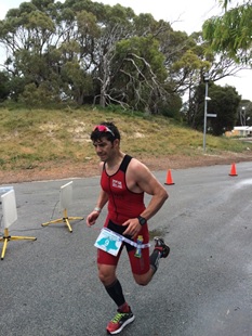
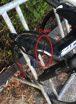
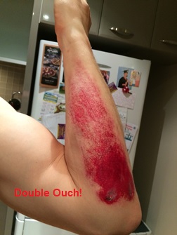
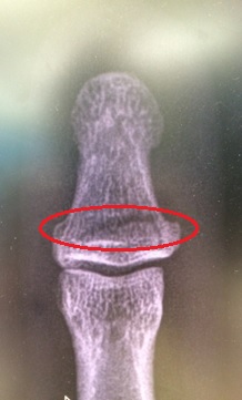
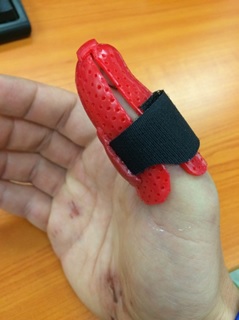
My Ironman (IM) trg has taken a bit of a hit. In a build-up half IM race I decided to trow myself off my bike but not forgetting to do my best superman impression before hitting the deck pretty hard. My initial annoyance was the damage to my bike; carbon fibre is costly! Although pretty battered, bruised and scratched (mainly to my pride), in good old Army fashion, I soldiered on finishing the remaining 20km of the bike leg and the 21km run. Post-race clean-up and a trip to A&E the next day confirmed I had actually broken my thumb; I did feel a fair amount of pain whilst trying to change gear – now I know why.
What impressed me most during my treatment was the thermoplastic thumb splint (available in a choice of colours) complete with water friendly Velcro securing strap, although I’ve already got some design mods in mind for version two. It means I can still compete in my next half IM trg race in 2 weeks’ time before the thumb is estimated to be fully healed 6 weeks from now.
Below are some pics…