Archive
Friday Night in Harrisburg
All new buildings are required to complete an Air Barrier Test (ABT) and the Defense Logistics Agency (DLA) HQ is no exception. The leakage rate is important because it indicates how much conditioned air is being lost to the outside environment. It costs money and energy to condition the air inside the building and so it is wasteful to allow it to leak out. More specifically, as the client USACE specifies an allowable leakage rate and if the building fails then the issue must be resolved. Given that the leakage rate is determined by the construction method of the building and this building is very much in the stage of finishes being applied there would be no quick fixes if it fails; so it’s important.
The test was completed on a Friday evening a couple of weeks ago with a provision for a test early on Saturday if required in order to avoid interfering with other trades as the building had to be sealed for the test. Dusk is generally considered the best conditions for testing as the dT between the building and outside is the greatest to be able to detect leak causes using thermal imagery. Sadly, as you will see below this doesn’t necessarily make for the best photographic conditions.
The test consisted of sealing up all ‘intentional’ openings, sealing a number of fans into one of the doorways and pressurising the building. The test was completed twice, first subjecting the building to a negative pressure and second subjecting it to a positive pressure. After a short while to allow the building to reach steady state it (where the pressure is not rising/falling) it could be assumed that the air leaking through the building’s skin was equal to the air the fans were blowing into, or out of, the building. The later was measured through a range of differential pressures to give the leakage rate. Whilst the an operator recorded these measurements for the first test, depressurising the building, the air tester and I walked around the building with the thermal imaging camera, and the less technical back of the hand, to identify any significant leaks. Any cold spots in the building skin or cool air blowing into the building were subject to investigation. For the second, pressurisation test, we walked around the outside to do similar but given the scale of the building this was less effective.
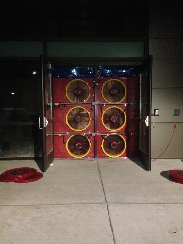
Fan bank 1. A second bank of 3 was put in a nearby doorway to provide sufficient flow rate to achieve steady state.

The system needs to read the same pressure at both fan banks. As the right hand bank has twice the number of fans of the left one it has twice the flow rate.
The standard.
The USACE standard is 0.25 CFM/75 sq ft enclosure, meaning cubic feet per minute per square foot of envelope at 75 Pa differential pressure. This, peculiarly for the USA is a single standard whereas in the UK we have a variety of rates to choose from depending on building usage. The units of measure in the UK are m3/hr50/m2, which is m3 per hour, per m2 of building floor area at 50Pa differential pressure. 2 m3/hr50/m2 is the UK standard for a low energy air conditioned office which is about 0.14 CFM/75 sq ft.
In an office building most of the floor area falls into this however, broadly speaking, unconditioned spaces are exempted; meaning that they have to be sealed off from the main building. Large complex buildings such as skyscrapers or buildings with significant restrictions to airflow, such as a single door separating two halves may be split into zones. The DLA HQ can be treated as one zone as there are large open plan areas and multiple stairwells and lift shafts. The building envelope is usually calculated by the Designer of Record (DOR) but in this case was calculated by the contractor, after a year of asking the DOR. The building is 309,240 sq ft, therefore:
0.25 x 309,240 = 77,310CFM is allowable for this building.
The leakage rate is tested at a differential pressure (between outside and inside) of 75Pa, which compares to 50Pa in the UK.
The practicalities of the test.
The sealing of ‘Intentional’ openings refers to closing all of the doors within the doorframes as well as any HVAC vents, kitchen flues and the waste vents. To ensure optimal pressure equlaisation within the building a few measures had to be taken:
- For every 500 sq ft of suspended ceiling at least 4 sq ft of ceiling tiles must be removed to promote pressure equalisation.
- All internal doors had to be wedged open; fortunately many aren’t fitted yet.
- The doors to the lift shaft had to be wedged open to ensure equalisation to the rooftop mechanical room.
The biggest issue was doors blowing open on the tests destabilising the pressure. The prime contractor had let all of their guys go, for the day, to ensure good running of the test having people, with some form of comms, ready to chase down open doors would have made the whole process a lot simpler. Having plenty of guys on standby would be something I imagine the RE would have got right!
Six of the nine fans used drew a maximum of 3kW. Each of the 230V circuits (the building has 110 and 230V circuits) had a 15A breaker meaning that it could only support one of these fans, or two of the smaller 1.5kW fans. This resulted in about 30 minutes of getting out electrical drawings, resetting breakers and moving extension leads around. The master electrician could have planned this prior to the test.
Results.
In the end the building passed with ease however there were still some interesting elements. The biggest loss areas are:
- Doors. Being freely moving there is always going to be a level of leakage through these. If the building had failed by a small amount then upgrading the seals would have been a way of marginally improving performance.
- Although none of the windows open, as they are penetrations into the buildings skin they act as a potential break and pathway. One window had a good breeze blowing through it that could have been sealed with a bit of mastic if required.
- Sockets and fittings, both internal and external. Again a penetration into the building’s internal skin where air can finally leak through.
- Architectural Interfaces. This would have been the main problem at the DLA HQ. Where differing building methods meet the interface can cause an issue if it is not properly sealed. An example is the auditorium on the DLA HQ which is essentially another building tacked onto the side of the main building. It was built using prefabricated panels, whereas the main building was cast in place. This had been identified as a risk in construction and was mitigated by the liberal application of spray foam.

A doorway. This is taken on the depressurisation test therefore the dark section is showing cold air blowing through the door seal.

The normal picture comparison was black. This shows an architectural interface between a precast structure and a clockwork construction with facade. As this is taken from the outside the bright yellow is showing warm air escaping.
The results came in last week showing that the building had leakages of 0.143 and 0.132 CFM/ft2 for pressurisation and depressurisation respectively. So it passed with ease in the USA, but might have only scraped through the UK equivalent test because of its complex architectural features.
Oz NDY – From One Hospital to Another.
Introduction
I’ve now been in the design office for 2 whole weeks, working in the Interiors/Tenancy Section in the Existing Buildings Department. In summary, we design all mech, elec and hydraulic services for existing building refurbishments, usually office/business fitouts. Overall office work leading up to Christmas has been a little frantic, mainly involving clearing deadlines and getting tenders out for new business for the start of the New Year. I have undertaken a few interim tasks as stated below with my first real project role coming in the form of an animal hospital fitout – kind of apt coming from the PCH project.
Interim Tasks
The following three tasks were given to me as more of a filler and introduction to the types of projects I’ll be getting involved in.
- Fee Proposal Review. A review of NDY’s fee proposal for the replacement of a generator exhaust. The mechanical contractor originally approached by the client were only a small company and felt the proposal was too detailed and consisted of too much management terminology for the simple requirement. There was nothing wrong with the proposal and we deemed it fit for purpose so advised the client to explain this to the contractor. If they still didn’t agree then we advised them to re-tender to a more suitable one; who could see past the management procedures and policies, that I feel they were deeming too complex.
- Giving Technical Advice via a Consultant’s Advice Note (CAN). The CAN was for the reprogramming of the BMS in a recent office fitout we had completed where two separate floors were adjoined by a central stair. The CAN gave a technical explanation for the need to consider both floors as one in terms of smoke management in a fire event when creating the fire and smoke cause and effect matrix.
- Restricted Return Air Path. This consisted of a study of the AHU return air path in a new office fitout where, due to the type of return air system used, being via extract grilles straight in to the ceiling void acting as a large plenum, it was found that obstruction from sections of full-height partition walls were restricting return airflow. We came up with a solution to install a number of transfer grilles through particular sections of the full-height walls. The trade off being potentially increased noise levels for better recirculation.
Short-term Projects
I have just started my first main project, my role being the Project Leader (PL) for the fitout of a new animal hospital. The current space if no more than an empty warehouse serviced by 3 No. Evaporative air-conditioning system linked through flexible ducting (which they seem to love over here). There is also an existing toilet and lighting throughout.
The PL roles sees me being the client facing project manager reporting to a Project Director (PD) who is also doubling-up as the mech technical lead. My boss (also mech biased) has been helping out and accompanied me to my first client meeting and site inspection; he will be on extended leave post Christmas till the end of Jan so has basically helped me get the project rolling.
In terms of detail at this stage our client, Perth Citi Fitout, are the Managing Contractor who have already put together construction force of various subcontractors based on the scope of works from their client, Vetwest. They have Nagel, architects, who have designed the fitout so we have a pretty good idea of what they want. The services are pretty straightforward with the bulk of design work being the mech air-conditioning system.
At present the MC has budgeted for a complete strip-out and new installed system so that’s exactly what we are going to design. We did see if the existing evap units might be useable but decided pretty quickly to replace them. This was mainly based on the poor effectiveness of evaporative cooling in high humidity conditions. Granted that the Perth climate conditions produce mostly dry heat but there are occasional humid spells in the winter months, which realistically would only offer a small delta T due to evaporation becoming more difficult proportional to the water content present in the air.
The MC issued us a concept mech layout but from our meeting and discussions over the number of HEPA filtration units required we went away and conducted our own research. The two main points were, the requirement for a grease trap for the wastewater drainage system and HEPA filtered units to be installed in all locations where animals would be.
Both of these are being investigated and I am awaiting specialist confirmation. My initial thoughts being thus:
Grease Trap. After stakeholder engagement it was identified that the areas where animals (primarily dogs) will be kept for long periods of time, the kennels and cages are fitted with special chemicals that soak up urine and water content in faeces. These are regularly cleaned out and disposed of in specific excrement waste bags so it is my view that normal wastewater drainage will be suitable. Of course the Water Corps may have a different view and I also need to check the Building Code of Australia (BCA) Guidelines.
Multiple HEPA Filters. Again after stakeholder engagement it was found that Vetwest are wishing to apply to the Australian Veterinary Association (AVA) to seek accreditation of their hospital accreditation scheme. The Vetwest proj mgr stated that under the AVA’s standard they required all air-conditioned spaces where animals are present to be HEPA filtered. It was evident in the mtg that they didn’t actually know how this worked as they were talking about mixing normal supply air and HEPA filtered air in the same space – which obviously negates the very clean air provided by the HEPA filters. What we did know was that just like in a human hospital the surgery room needs to be supplied by HEPA filtered air but I don’t think other areas do. To confirm I researched the AVA standards and found nothing relating to HEPA filtration at all so posed the question to one of their standards testers – I’m awaiting a reply.
NDY’s Concept Design
With these answers outstanding I cracked on and came up with a concept mech (air-conditioning) layout. I split the space into four zones and plan on using 4 No. Packaged DX Units (yet to be specified). These DX units will be mounted on the roof (where there’s plenty of space) and consist of ridged ducting for the main run with flexible ducting to each supply air grille. Figure 1 shows the draft concept design. This along with a Consultant’s Advice Note (CAN) explaining our justifications for the system type will be finished off and sent to the MC for comment before Christmas.
Post Leave Continuation
On my return from leave and after consultation with the MC over our concept design I will then begin the detailed design. This will initially consist of using a software package called Trace which gives you heat load calculation so I can then size my packaged units. I’ve had a quick play with it already and it’s very similar to Hevacomp but with more experience I’ll try and draw out some more detailed comparisons. Then I’ll have to size all the ductwork to achieve the correct flow rates etc that will lead to cost planning. At the moment the MC has quoted AUD $55k for 3 No. units and our 4 No. Packaged DX Units is looking around the AUD $70k mark. I will then move on to the hydraulic system, mainly consisting of a reticulated Oxygen supply and Suction system.
Project Reflection
Being part of the Interiors/Tenancy Section means that I will hopefully have a number of short-term design projects to PL on. This will provide me with a good basis for reflection and help steer subsequent projects in order to build on my professional development and focus on any outstanding UK-SPEC requirements.
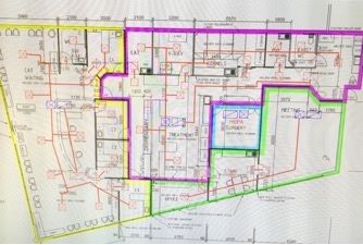
Figure 1. NDY Concept Mech Layout
This just leaves me to say I won’t be blogging for about 4 weeks as I’m now on Christmas leave…have a Merry Christmas and a Happy New Year!
Why?
This blog aims to give those heading out on phase 2 another reason to keep annoying people by asking ‘why’.
Civil students might remember John Moran talking about the Specification for the concrete on a bridge being built in Australia in 2014 (I think it was Pete Mackintosh?). His joke was that the only thing that would see the bridge was a dingo, and that the aesthetics were irrelevant. I am also with JHG, and may have spotted a dingo of my own.
My thesis is centred on the use of GRP over concrete jacking pipes in medium diameter (1720mm OD) drainage schemes. Amidst the mad panic of downloading and attempting to speed read every document imaginable off the IHS, I stumbled across the Technical Design Guide from the CPSA (Concrete Pipeline Systems Association).
Interestingly, it states that for design purposes, Water UK recommends a Ks (roughness) value of 0.6mm for storm water, and 1.5mm for foul sewers – irrespective of pipe material. The Client’s specification on my project (and the Client is a local water authority) states the internal surface roughness of the sewer pipe must have a Colebrook White Roughness Coefficient of 0.01mm or less. I would understand (sort of) if it was a storm water drainage scheme, but we are constructing a foul sewer. Fortunately, the GRP pipes we are using do comply with the 0.01mm Ks, but why should they?
The sewer system we are building is in a greenfield site – the land will be progressively developed and expects a population growth of 260,000 over the next 25 years. The CPSA notes that when there is a small flow, it is unwise to select too large a pipe ‘to allow for possible development’ as it may lead to settling out of solids, long retention periods, blockages and build-up of septicity. Obviously the 110,000 homes and their 260,000 residents are not going to magically appear when the sewer is completed next year – the demands placed on the sewer will increase gradually. Perhaps the ‘over-specified’ roughness coefficient is the result of clever design for the entire life cycle of the sewer, with greater emphasis placed on the hydraulic performance of the pipes in its early years to ensure that the risk of blockages etc. is mitigated without the need to install a greater number of smaller diameter pipe networks at an increased cost.
My opinion is that the Client is focussed on delivering sustainable solutions through design. Maybe it was not a dingo after all.
Have a good Christmas break.
Forth Road Bridge
Hello all,
You may or may not have heard about the problems associated with the Forth Road Bridge near Edinburgh. I have been passed some info that I though may interest some of you out there….
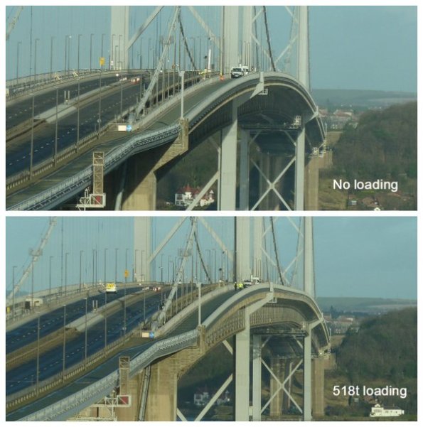
The images below are from a load test done a couple of weeks ago. Achieved using lots of full gritter lorries with drivers on danger money wearing armbands! Some interesting facts:
- The bridge spans just over a kilometre between the piers. It was the 4thlongest suspension bridge in the world when opened in 1964.
- The piers are 156m tall (about half the height of the Eiffel tower, and about the same as Lomond or NEV from seabed to flare tip)
- The bridge contains 40,000Te of steel
- The maximum tension in the main cables is about 25,000 tonnes at the mid span
- The main cable tensile stress is incredibly high at 1050MPa (N/mm2), which is about the same as a 17 stone man suspended from a 1mm2guitar string (nice image there – sorry)
- Each tower supports 8000Te imparted from the main cables.
The part that failed was an inverted steel ‘goalpost’ that is attached to the bottom of one of the deck hanger cables. It almost certainly suffered fatigue damage, ie too much stress cycling caused by heavy lorries. When it was opened in 1964 it was designed for 25,000 vehicles/day, and the maximum lorry weight was 24Te. Today it sees 70,000 vehicles/day and the maximum lorry weight is 44Te. If the steel component had completely parted, the consequences are debatable. In the worst case it could have caused a section of the road deck between the hangers to tip, possibly causing the combination of 4 or 5 heavy lorries (that would cause such a failure) to crash.

Bedding In – Ph3
I’m in my second week working CH2M (previously known as Halcrow) working for the Ports and Maritime Division and suprisinly…I’m enjoying it!!!
I don’t intend to go into any detail in this blog but rather set the scene and prompt questions should anyone have any.
I have joined the Queen Elizabeth Class (QEC) project which is designing the dock that will birth the new aircraft carriers in Portsmouth. DIO are the client and VolkerStevin are the contractor.
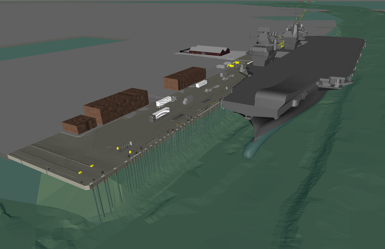
The dock is an existing 19th century sea wall with a 1930s and 1970s series of jetty attached to it. The water depth alongside the jetty is sufficient for the new boats however, the jetty capacity is well below the new requirement.
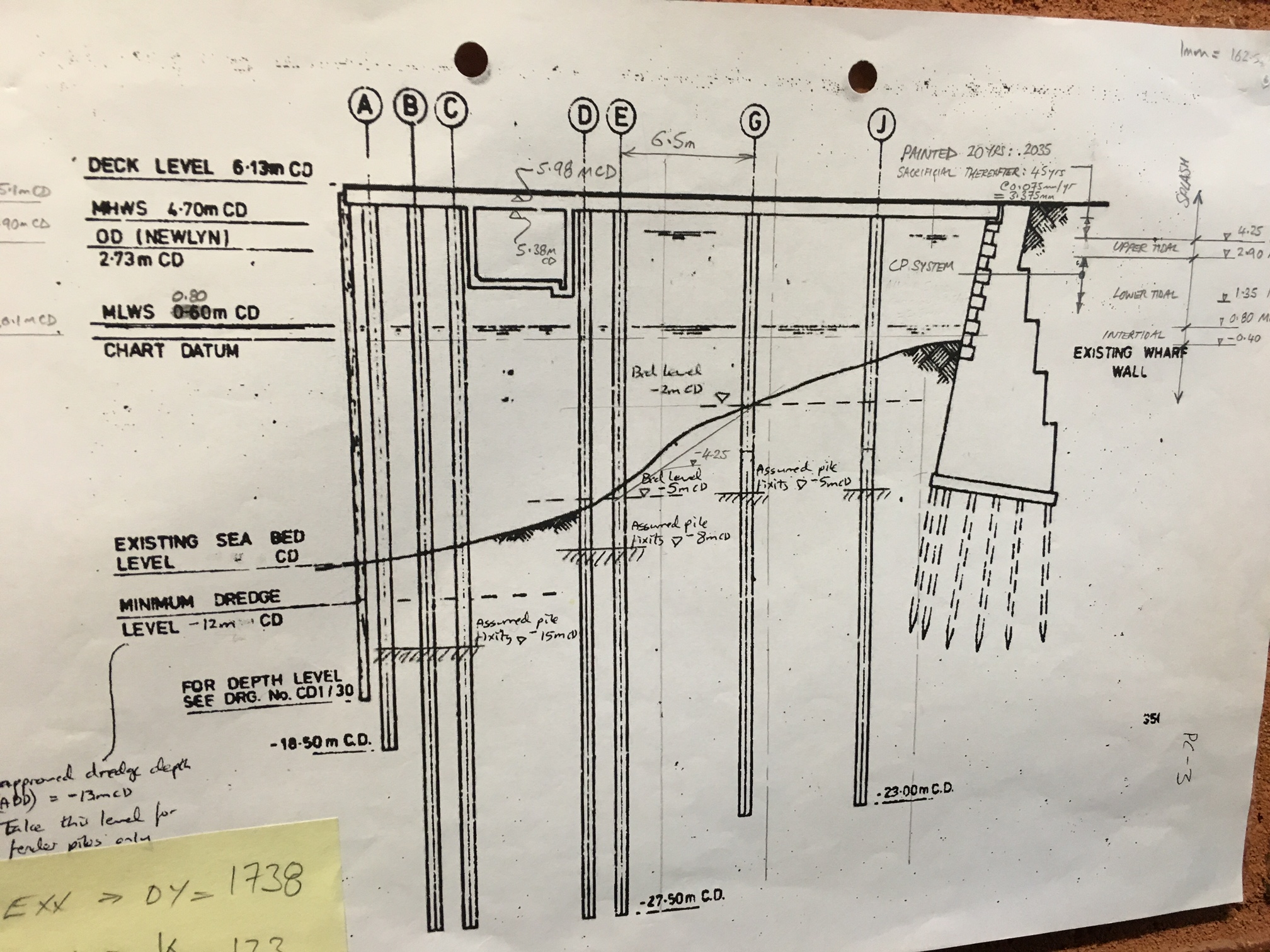
The key loading on the jetty platform will be :
Vertical – bogie point loads from the mobile cranes. The jetty will also house a new M&E shed that will house all of the ‘wizards boxes’ used to generate the electrical feed required for recharge (these are pretty big and heavy). Finally, the jetty will be expected to support lorries and container stacks all over the place.
Lateral – the boat hitting the dock when it parks (technical term), 100tn.
The plan
– Two large section of the jetty deck will be demolished and rebuilt.
– One strip of the deck will be cut out to allow new piles to be threaded through the existing.
– A number of holes will be cut out to allow new piles to be fed through, many racked to facilitate the lateral loads.
– 2m concrete deep beams will be inserted under the deck across the top of the new piles.
– Pre-cast slabs will fill the holes.
– A new deck will be cast in-situ to thicken the whole deck with a single in-land crossfall.

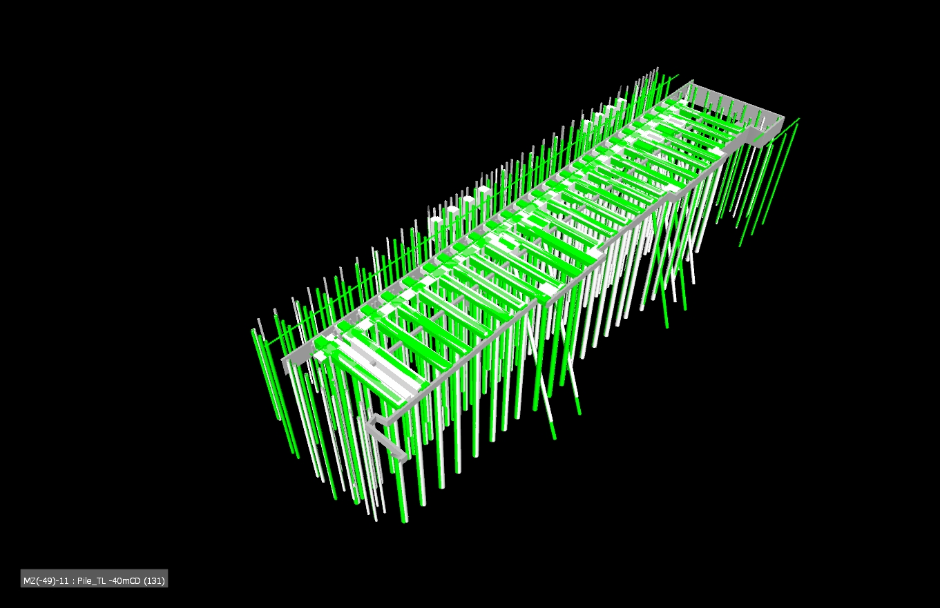
Grey is existing, green is new
ICE CPR
Two of my identified weaknesses when moving to Ph3 were technical design/analysis and working with existing structures. I think this project will serve me well!
Remove the reins
My first job has been to conduct a shear check between the existing and the new decks where the mooring bollards are located. The bollard rating is sufficient and the bolting down design has been verified but it was unknown whether the deck would simply rip apart. EN 1992-1 has a section on concrete poured at different times so that became my starting block however, it assumes the shear failure would occur due to bending so attempts to use the lever arm from the bottom steal to the shear plane (it assumes you are looking at a composite beam and slab arrangement). I knew this made no sense and after a long time (a very, very , very long time) I realised what the problem was and substituted to for F/A. The rest became code bashing exercise of mumble jumble Greek. The key take for me is that I knew it wasn’t right and knew where to go to sort it out. That may sound like a small thing but the kudos of presenting output without direction on my first tasks seems to have served me well and boosted my confidence for the next six months!……….Who’d a thunk I could produce a calc with Damo’s help 🙂
In other news
My office has the design contract for the Middle East Basing (think Op Shader). I was asked to look at a deployment order to send some CH2M Engrs out for technical design support to delivery. Page two of the doc had the CoC outlined and OC STRE sat at the top of the tree…like a slap in the face I was reminded of my day job after this process ends.
I did that!
A074754 – 229 – 300 – Drainage Layout
…Unless it doesn’t work in which case someone else did it!
Today I received a pdf of the drainage design I did back from the drafty in Nottingham who drew it for me (see link above).
The site is an old National Grid gas storage site. A large part of it was sold off to Barrett homes who then built houses on it. In doing so they destroyed the drainage outlet and so now the site floods. A lot. So much so that the water is spilling over a small retaining wall at the north of the site and into a timber yard. The timber yard then floods and they claim against National Grid for the damage to their stock. National Grid have been saying to them for ages (the houses were build nearly 10 years ago) that they would do something about it and are only getting around to it now because they want to demolish the northern gas storage tank and the ground it too wet and soft to get the plant across.
To the west of the site and atop a retaining wall is another development. The drainage behind the retaining wall discharges onto the National Grid site and is causing the majority of the flooding. A manhole was once constructed there but never connected to anything. We’ve devised a ground drain to deal with the surface water while also lowering the ground water. This feeds into a new underground drainage system which then discharges into the river the far side of the road in the east.
The drainage design was pretty straight forward. I designed a similar temporary drainage solution during Phase 2 when the basement flooded (there is a blog about that one too). For this one all the leg work had been done for me, a drainage specialist in another office had run simulations and done other clever computer things and advised on a 150mm dia pipe running at a minimum fall of 150mm.
So all I had to do was draw some straight lines on a site diagram and specify the manhole types, invert levels and a few other bits and pieces that i’s learnt when doing it on site. Doing it on site previously actually gave me a huge advantage, I knew to specify a rocker pipe connection, a geotextile membrane and rocker pipe connections. All that stuff which is easily overlooked but important to making it work and not looking like a knob.
National Grid want to sell this bit of land as soon as the gas storage site is gone (probably to Barrett again) and so don’t want any on-going maintenance issues. Therefore the design must comply with the Anglian water adoptable sewers regs. So with a bit of reading I made sure the manholes, falls, diameters and all the other bits met the spec.
Now comes the hard part… In order to discharge into the river I need two things:
- Consent from the Environment agency to discharge into the river – this is actually easier than you’d think. We tested the water so we know it’s clean enough, so all we do is show them how we’ll be working safely next to the river and how we won’t constrict the flow. They then give us consent.
- Section 50 consent to dig up the road from the highways agency. This is more difficult. I’ve submitted our design Colchester tomorrow to meet with some bloke to take about crossing the road. Apparently they can only talk to me on site, they wouldn’t even tell me what depth they wanted it under the road in order to miss other services until I’ve met the bloke. Not sure what all the cloak and dagger stuff is about but it’s a day out of the office I suppose! The really kicker is that before they’ll give you consent you have to give them a cheque for however much they think it’ll cost to reinstate the road in case you dig a massive hole then leave it (or go bust).They also charge you for maintenance of whatever service you’re instating despite the fact that they also ask you to prove it will be adopted by the relevant undertaker.
I’m also told the bloke in question is mega boring, I’ll let you know how it goes…
Chartered – Tick VG
Nothing significant to report from site, where there is a bit of a hiatus as paperwork catches up to progress and the design office where I am writing up results of surveys. However in the sidelines I am now Chartered, as a manager. So I thought it worthy of a blog.
For those who haven’t seen 2014DIN07-093, here it is hosted from the Chartered Management Institute (CMI) website.
The offer runs out in April 2016, though new direction may/may have come out. This DIN allows you to apply for a qualification from either the CMI or the Institute of Leadership and Management (ILM). I elected for a level 5 certificate in Management and Leadership from the CMI, which came with a year’s free membership. I elected to go with the CMI qualification as it led towards Chartering through the CMI’s fast track route and I thought that this would be a good way of demonstrating management capability in the future. Clearly I am now on the hook for both future management CPD and further professional fees, but at present I see it as complimentary to my engineering development. It also provides another independent verification on elements of competencies C – E.
I have to say the application process underwhelmed me; I put a couple of evenings into my 1200 word application form and was told I would be informed within 10 days. This turned out to be less than 24 hours which either says there was a super fast-track approval system where they see the words ‘Army Captain’ and reached for the ‘Tick VG’ stamp. When comparing the system to Chartering as an Engineer the two biggest differences are:
- Education: A level 5 certificate is clearly significantly lower than a Masters degree. This is true in volume when one considers finishing phase 1 of PET would count as a certificate. It is also true in level of thinking, with a Masters sitting at level 7 in the NVQ scale; I’m sure everyone is familiar with the term ‘Masters level learning’ by now…
- Application and interview. Whether it is the 1,000 words for the CMI, 3,000 for IMechE or 6,000+ for the ICE the form is about demonstrating applying theory into practice, experience and lying about keeping up a CPD record. The interview though I think is very different though, because of the lying piece. I spent a bit of time putting together my application but without seeing me how can the CMI verify it was me that wrote the application form or even did the work. It makes it difficult to maintain a standard.
I have not looked into any other industries to see what their requirements are but I think, unlike George Orwell’s animals, all Charters weren’t created equal. To track back to engineering the American equivalent of CEng is P.E., simply Professional Engineer. This is considered a licence and like most professional licences is administered at State level. The prerequisites are a Batchelor’s Degree and 4 years of experience. Then you are able to take the PE exam, this is a 4-hour morning paper followed by the same in the afternoon. This appears to have scarred the people in my office to an equivalent degree to Ex Longreach or Worst Encounter as it often pops up in conversation. So as far as comparing the UK and US approaches they appear equivalent to me as I think, without seeing a copy of the paper, that it will be at ‘Master’s Level’. That said, I would say that the PET course has caused me to be far more analytical as a result of writing TMRs and AERs, something I wouldn’t have got from a big exam.
Conscious that I haven’t given Mike any pictures yet, one thing that is better over here is you can buy a PE bumper sticker:

If you want one get your bids in…
In other news, don’t go to New York City in December, it is full of people. As you can see below even Picasso’s goat is unimpressed with the crowds.
Thames Tideway Tunnel – The start
Thames Tideway Tunnel – The start
I have now started on Phase 3 with Arup and am working within the geotechnical team on the Thames Tideway Tunnel project. To avoid this blog getting too long I’ll present some of the background, my part in the plan and a brief discussion on sustainability.
Background. The London sewer network is predominantly a combined foul and surface water system. The sewers convey the waste to treatment works for processing. However, when it rains heavily the capacity of the sewers is often overwhelmed and the excess sewage is deposited into the Thames through combined sewer outfalls. To reduce the frequency of incidents of raw sewage discharge into the Thames each year the Thames Tideway Tunnel project aims to capture combined storm and foul water within a new 7.2m diameter tunnel running from Acton in the west to Abbey Mills in the east.
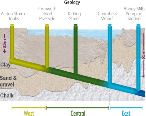 Overview of tunnel alignment through the London geology.
My part in the plan. Effectively the project is divided into three sections: west, central and east. Each section has a number of connections to capture the existing combined sewer outfalls and convey the flow into the new sewer. The process is generally to have an interceptor chamber which feeds into a further set of chambers to attenuate flow and then a drop shaft to connect to the new sewer. I have 2 sites to design the foundations for: Putney and Barn Elms. Arup are not responsible for the main sewer tunnel or drop shafts but are responsible for designing the other elements, including the chamber and connecting culvert foundations.
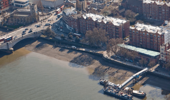 View of Putney Foreshore Embankment site
Putney has some interesting challenges: The connection to the existing sewer outfall is directly below Putney bridge. One of the proposals sees there needing to be a number of bored piles in the foundation design (questionable reasons: either as tension piles to avoid buoyancy issues or to minimise long term settlement between existing bridge outfall and new structure). Getting a piling rig into position will be a challenge due to headroom constraints. One method sees a temporary sheet pile wall planned to be installed around the whole site area (under the centre of one of Putney bridge arches (max headroom)), then dewatered, excavated and re-filled. The temporary works are out of my scope but understanding how the contractor will carry out the works is clearly important.
 Existing outfalls (left), proposed interception chamber on right – this is 7m deep with a number of bored piles within the foundations proposed!
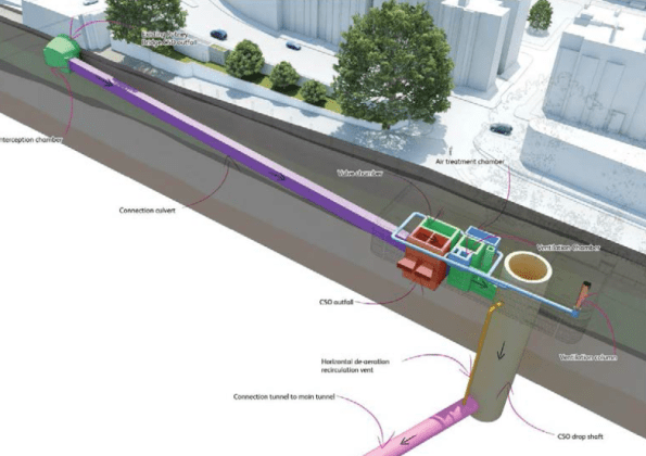
My responsibility is designing the interception chamber (left green), connecting tunnel (centre purple) and attenuation chambers (right brown/green/blue) foundations. Drop shaft and connecting tunnel to main sewer (out of picture) is not my responsibility.
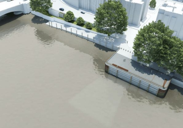 Illustrative view of completed site.
So in terms of what I am doing – initial work is scoping further ground investigation for where there is risk – lack of confidence in certain parameters for example. Next comes a geotechnical design report and then will come developed design, detailed design and finally construction issue information. This aligns pretty well with the RIBA stages of work too.
Sustainability.
The aim of the project is to provide overflow capacity to the existing sewer infrastructure in order to reduce the frequency of sewage discharges into the river Thames.
Advantages and Disadvantages. This project will bring political and social benefits of a cleaner river and evidence of better waste management practices within the UK. The economic benefit is more questionable. Construction costs have multiplied by a factor of 3 from 2005 to £4bn raising the question of its cost worthiness. Moreover, other options of attempting to use land as attenuation (green field sites as soakaways, green roofs) through green infrastructure have been argued to be sufficient to meet the demands of future predicted storm levels. The legislation is in place to enforce greener infrastructure but it appears planning authorities do not follow this through as judicially as they might with greater resources.
The accuracy of the sewage over flow statistics has been questioned, with some groups stating that the level of pollution entering the Thames is lower than the Environmental Agency’s limits now and so the construction of the new sewer is a complete waste of money.
As part of the project, the Beckton Sewerage Treatment Works will also be upgraded to cope with additional demand. The disadvantage of increasing the amount of surface and foul water captured will be the need to pump all of the water through 60m of head at Abbey Mills which will result in higher maintenance costs and require significant energy to achieve. If some of the storm water had been captured through green infrastructure assets there would be less energy required to process it at the other end. Reducing the amount of storm water ever reaching the sewer therefore brings a double saving.
Clearly reducing the sewage discharge into the Thames is beneficial and the project will significantly improve the condition of the river. I suspect as a country likely to be at the forefront of developing environmentally friendly solutions the green infrastructure piece will come but for now at least a solution has been produced to an acceptable cost, timeframe and quality, assuming all goes to plan!
In summary. This project will be my sole focus. I have started to investigate wider strands within it – financial/commercial for a better background understanding but with a company like Arup, unless specifically requested, phase 3 will tend to be focussed on one major project.
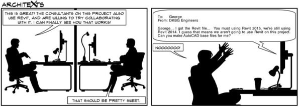
Oz NDY – REVIT vs AutoCAD Discuss…

Introduction
This blog aims to get a discussion going on the topic of utilising CAD packages in your design offices. I’ll kick-off with NDY’s set-up…
REVIT is seen, pretty much construction industry wide and certainly at NDY, as the flagship CAD package. We have a dedicated CAD team that solely use REVIT, although skills do exist for other CAD packages such as AutoCAD.
NDY promote their use of REVIT and like to express this to their client base so they are seen as operating with the latest industry technology. However, there is a problem. I’ll use my current section, Interiors, as an example of a typical project.
Problem
The Interiors Section of the Existing Buildings Department focuses on short-term projects, usually 6 – 8 wks. Therefore, turn-around times for CAD drawings, in particular, are tight. If the design is of specific technical complexity then usually REVIT will be: a) requested by the client and b) preferred by us as we can programme in the CAD requirements and resource through our dedicated CAD team. However, due to short project deliverable timelines and sometimes more basic CAD requirements along with client requests for only needing simple drawings, it can be a lot quicker if these are created ‘in-section’ (opposed to in-house) using AutoCAD. This negates the need to resource to the CAD team which they prefer as their bread and butter work, for the core departments working on large complex projects, can continue unhindered.
The AutoCAD capability exists in the Interiors Section so this affords us great flexibility in managing project deliverables and in-turn removes pressure from the wider office.
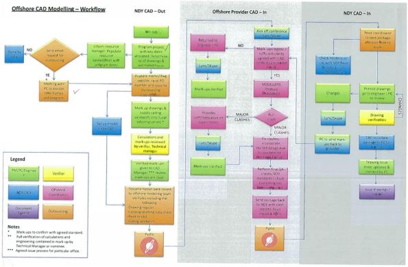
In addition, NDY also have an outsourcing capability in Indochina where we have a process in place that outsources CAD requirements. A great capability but for short-term work the lead-time required for the process to work efficiently means that we still prefer to do this in-section. It also means we can make amendments and re-issue drawings in the most efficient and effective manner.
As time is money you can see how this creates cost savings, especially when you compare the technical skills required between using basic AutoCAD and REVIT.
Discuss…
I’ll leave it there with the hope to spark a discussion about your experiences and thoughts…
Edited with Outsourcing CAD process.
Oz NDY – Transitions In More Ways Than One
Introduction
In this blog I will cover the lead up to transitioning between Phase 2 & 3. It aims to help out the Phase 1 students and hopefully give you a few pointers come your impending move – it rushes up faster than you think!
Background
You will be fully aware that Phase 2 in Australia is set-up with John Holland Group (JHG), so apart from sorting out your own admin for the move, work wise things should be plain sailing. However, you should also be aware that Phase 3 – Design Consultancy attachment is partly up to you to organise.
My Experience
The most important thing to factor in is time. Eight months flies by and you really need to give the move some thought early on, allowing sufficient lead-time to jump through a few hoops. My experience could be classed as atypical as I tried to break from what my predecessor did but for, at the time, what I thought were good reasons.
The norm is for the student to move to the office of whoever the design consultancy was for your JHG project. This has pros and cons:
Pros
- You will have had some interaction with them at some point on your project and hopefully built-up a good rapport.
- You may be able to visit their office through working on an area of the project; a great way of meeting more employees but more importantly get a feel for the vibe of the office. I did this and it really helped with my decision.
- If the previous PET student went there then they will have a very good understanding of what the programme is all about and importantly how to manage you. I think this is invaluable and sealed the deal for me in the end. Although it’s not difficult to inform a new office of all that info, they may have a different agenda for you and by the time you work that out it might be too late.
- Equally, if the student you follow is a good egg then the office will understand your experience, capabilities (especially managerial) and general ‘can-do’ attitude. This can also be tempered with them knowing your other commitments; academic studies etc.
- It also reduces the number of hoops and admin for JHG and the design office to do.
- I was told that for conflict of interest reasons that I would categorically not be working back on the JHG project. This is a positive thing as it gives you a clean break and doesn’t get you working on the same project tasks; potentially reducing your chances of gaining more breadth in usually much needed competency areas. It doesn’t however stop you from imparting your newly gained knowledge and experience to help out your design office colleagues; only being in the office for three days I managed to do this with one of my very first tasks as I have the understanding from being familiar with NDY documentation.
- Another related positive is your ability to see things from the other side of the fence and maybe understand why certain decisions were made without the JHG inflated spin.
Cons
- You may have had to deal with the design consultancy staff whilst wearing your Managing Contractor (MC) hat where you may have had to show bias to the MC in order to please your chain of command, only to then find yourself working alongside the design office staff or be a member in their team.
- There may be other design consultancies that have better projects on the go.
- A diminished office and demotivated atmosphere. They used to occupy the entire 11th floor but have reduced in size due to reduction in work and so are looking to lease out the other half of the office. [I have to say that although they have condensed into a single side of the office the atmosphere and spirit seems good].
Decision
It may seem, from the pro – con balance, that it’s a no-brainer in following-on in your predecessor’s footsteps. But, there may be very good reasons for a change. For me NDY were having a rough ride at the hands of JHG’s management on the PCH project and there were a number of design challenges, which no amount of senior management meetings on the 18th green were going to resolve; there could still be a court hearing come the end of the project. To that end and with repeated warnings (slurs) from JHG staff it seemed like a good idea to at least investigate alternative attachment opportunities.
I engaged with two other big consultancies in Perth, Wood & Grieve Engineers (WGE) and WSP Parsons Brinckerhoff. WGE had won the bid for the new Perth Stadium, which I thought looked like a great project but unfortunately they had been laying staff off and presentationally they said it wouldn’t look good taking on new blood. WSP was more of the services director at JHG trying to line me up with their office, but i just couldn’t shake the feeling that somehow it was mates doing each other a favour and so didn’t feel my best interests were at heart.
For both I did a fair amount of research, rewrote my CV, covering letters etc and even used known acquaintances on the inside to at least get an interview (hence the comment above about needing lead-time). After weeks of not really getting anywhere it was on the advice of another design consultancy, Cundall, whom I was working with on the PCH project who gave me the low-down on each prospective office and ultimately helped me make my decision to stick with the original plan and join NDY.
I suppose the important point here is to not just follow the norm because that’s what others before you did. Investigate for yourself and use as many sources at your disposal as possible to aid you in your decision. But remember this… it is you that’s going to be working at the office for the next 6 months and it’s your needs and requirements that must be met, which therefore should be your priority over everything else; remember the end-state is to become a Chartered Engineer.
I don’t know if any other Phase 3 students would like to echo my experience or add their own?
In Other News
I completed Ironman Western Australia at the weekend. A tough 6 month training programme, juggling work and study, resulting in a lot of blood (when I broke my thumb) and sweat, but thankfully no tears. I managed to get a PB in a total time of 12hrs 7mins (beating my previous best by 1hr 13mins) for the 3.8km swim, 180km bike and 42.2 km run.

Enter a caption
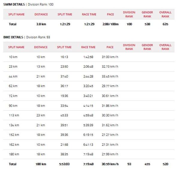
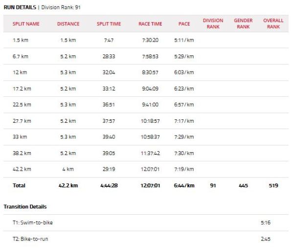
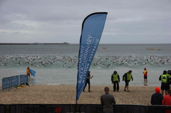
The weather caused mixed emotions with high morning wind and rain creating 1 – 2 metre swell, causing somewhere near 100 participants to jack-it-in through vomiting and general panic during the sea swim to sections on the bike course cycling into a 50km/h head wind. Thankfully though the cloud cover and low 21°C temperature meant a cool bike and run. With 1205 competitors starting, coming home in a divisional ranking of 91st (based on age category) and 519th overall, I was broadly happy. As a comparison the winner, a pro-athlete completed the course in 7hrs 55mins, an Australian course record – phenomenal!
At least now I can have my life back, lie-in at the weekends, not feel guilty about missing a training session and drink alcohol…until next time; which won’t be anytime soon, well not for the long course anyway!
Enter a caption
Sea swim around the iconic Busselton Jetty – you can just make out the turn point in the distance.
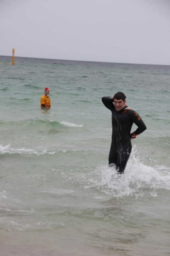
Enter a caption
Glad to be out of the washing machine.

Enter a caption
90km down – another 90km to go!

Enter a caption
Only a marathon to finish off.

Enter a caption
Done!
