Archive
Forth Road Bridge
Hello all,
You may or may not have heard about the problems associated with the Forth Road Bridge near Edinburgh. I have been passed some info that I though may interest some of you out there….
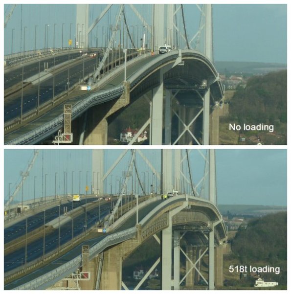
The images below are from a load test done a couple of weeks ago. Achieved using lots of full gritter lorries with drivers on danger money wearing armbands! Some interesting facts:
- The bridge spans just over a kilometre between the piers. It was the 4thlongest suspension bridge in the world when opened in 1964.
- The piers are 156m tall (about half the height of the Eiffel tower, and about the same as Lomond or NEV from seabed to flare tip)
- The bridge contains 40,000Te of steel
- The maximum tension in the main cables is about 25,000 tonnes at the mid span
- The main cable tensile stress is incredibly high at 1050MPa (N/mm2), which is about the same as a 17 stone man suspended from a 1mm2guitar string (nice image there – sorry)
- Each tower supports 8000Te imparted from the main cables.
The part that failed was an inverted steel ‘goalpost’ that is attached to the bottom of one of the deck hanger cables. It almost certainly suffered fatigue damage, ie too much stress cycling caused by heavy lorries. When it was opened in 1964 it was designed for 25,000 vehicles/day, and the maximum lorry weight was 24Te. Today it sees 70,000 vehicles/day and the maximum lorry weight is 44Te. If the steel component had completely parted, the consequences are debatable. In the worst case it could have caused a section of the road deck between the hangers to tip, possibly causing the combination of 4 or 5 heavy lorries (that would cause such a failure) to crash.

Bedding In – Ph3
I’m in my second week working CH2M (previously known as Halcrow) working for the Ports and Maritime Division and suprisinly…I’m enjoying it!!!
I don’t intend to go into any detail in this blog but rather set the scene and prompt questions should anyone have any.
I have joined the Queen Elizabeth Class (QEC) project which is designing the dock that will birth the new aircraft carriers in Portsmouth. DIO are the client and VolkerStevin are the contractor.
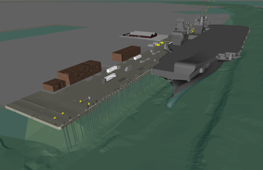
The dock is an existing 19th century sea wall with a 1930s and 1970s series of jetty attached to it. The water depth alongside the jetty is sufficient for the new boats however, the jetty capacity is well below the new requirement.
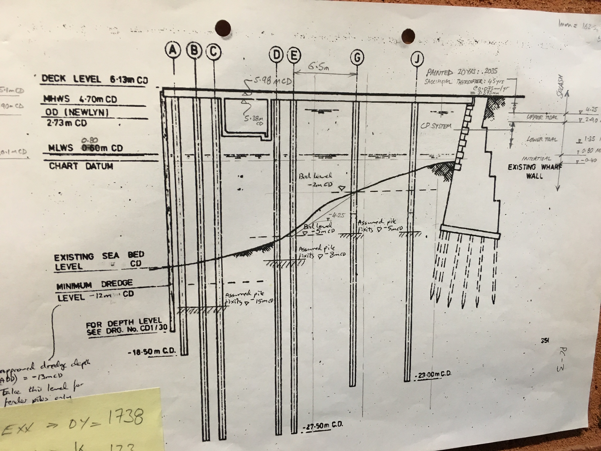
The key loading on the jetty platform will be :
Vertical – bogie point loads from the mobile cranes. The jetty will also house a new M&E shed that will house all of the ‘wizards boxes’ used to generate the electrical feed required for recharge (these are pretty big and heavy). Finally, the jetty will be expected to support lorries and container stacks all over the place.
Lateral – the boat hitting the dock when it parks (technical term), 100tn.
The plan
– Two large section of the jetty deck will be demolished and rebuilt.
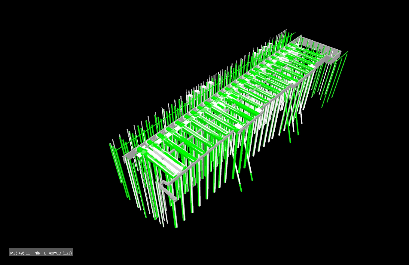
– One strip of the deck will be cut out to allow new piles to be threaded through the existing.
– A number of holes will be cut out to allow new piles to be fed through, many racked to facilitate the lateral loads.
– 2m concrete deep beams will be inserted under the deck across the top of the new piles.
– Pre-cast slabs will fill the holes.
– A new deck will be cast in-situ to thicken the whole deck with a single in-land crossfall.

Grey is existing, green is new
ICE CPR
Two of my identified weaknesses when moving to Ph3 were technical design/analysis and working with existing structures. I think this project will serve me well!
Remove the reins
My first job has been to conduct a shear check between the existing and the new decks where the mooring bollards are located. The bollard rating is sufficient and the bolting down design has been verified but it was unknown whether the deck would simply rip apart. EN 1992-1 has a section on concrete poured at different times so that became my starting block however, it assumes the shear failure would occur due to bending so attempts to use the lever arm from the bottom steal to the shear plane (it assumes you are looking at a composite beam and slab arrangement). I knew this made no sense and after a long time (a very, very , very long time) I realised what the problem was and substituted to for F/A. The rest became code bashing exercise of mumble jumble Greek. The key take for me is that I knew it wasn’t right and knew where to go to sort it out. That may sound like a small thing but the kudos of presenting output without direction on my first tasks seems to have served me well and boosted my confidence for the next six months!……….Who’d a thunk I could produce a calc with Damo’s help 🙂
In other news
My office has the design contract for the Middle East Basing (think Op Shader). I was asked to look at a deployment order to send some CH2M Engrs out for technical design support to delivery. Page two of the doc had the CoC outlined and OC STRE sat at the top of the tree…like a slap in the face I was reminded of my day job after this process ends.
I did that!
A074754 – 229 – 300 – Drainage Layout
…Unless it doesn’t work in which case someone else did it!
Today I received a pdf of the drainage design I did back from the drafty in Nottingham who drew it for me (see link above).
The site is an old National Grid gas storage site. A large part of it was sold off to Barrett homes who then built houses on it. In doing so they destroyed the drainage outlet and so now the site floods. A lot. So much so that the water is spilling over a small retaining wall at the north of the site and into a timber yard. The timber yard then floods and they claim against National Grid for the damage to their stock. National Grid have been saying to them for ages (the houses were build nearly 10 years ago) that they would do something about it and are only getting around to it now because they want to demolish the northern gas storage tank and the ground it too wet and soft to get the plant across.
To the west of the site and atop a retaining wall is another development. The drainage behind the retaining wall discharges onto the National Grid site and is causing the majority of the flooding. A manhole was once constructed there but never connected to anything. We’ve devised a ground drain to deal with the surface water while also lowering the ground water. This feeds into a new underground drainage system which then discharges into the river the far side of the road in the east.
The drainage design was pretty straight forward. I designed a similar temporary drainage solution during Phase 2 when the basement flooded (there is a blog about that one too). For this one all the leg work had been done for me, a drainage specialist in another office had run simulations and done other clever computer things and advised on a 150mm dia pipe running at a minimum fall of 150mm.
So all I had to do was draw some straight lines on a site diagram and specify the manhole types, invert levels and a few other bits and pieces that i’s learnt when doing it on site. Doing it on site previously actually gave me a huge advantage, I knew to specify a rocker pipe connection, a geotextile membrane and rocker pipe connections. All that stuff which is easily overlooked but important to making it work and not looking like a knob.
National Grid want to sell this bit of land as soon as the gas storage site is gone (probably to Barrett again) and so don’t want any on-going maintenance issues. Therefore the design must comply with the Anglian water adoptable sewers regs. So with a bit of reading I made sure the manholes, falls, diameters and all the other bits met the spec.
Now comes the hard part… In order to discharge into the river I need two things:
- Consent from the Environment agency to discharge into the river – this is actually easier than you’d think. We tested the water so we know it’s clean enough, so all we do is show them how we’ll be working safely next to the river and how we won’t constrict the flow. They then give us consent.
- Section 50 consent to dig up the road from the highways agency. This is more difficult. I’ve submitted our design Colchester tomorrow to meet with some bloke to take about crossing the road. Apparently they can only talk to me on site, they wouldn’t even tell me what depth they wanted it under the road in order to miss other services until I’ve met the bloke. Not sure what all the cloak and dagger stuff is about but it’s a day out of the office I suppose! The really kicker is that before they’ll give you consent you have to give them a cheque for however much they think it’ll cost to reinstate the road in case you dig a massive hole then leave it (or go bust).They also charge you for maintenance of whatever service you’re instating despite the fact that they also ask you to prove it will be adopted by the relevant undertaker.
I’m also told the bloke in question is mega boring, I’ll let you know how it goes…
