Archive
Making Neil proud – again
No, I don’t mean I have just bought a shocking pink brad-esque jumper, I am in fact currently wading my way through NA to BS EN 1991-2:2003 in an attempt to calculate the load on a concrete slab that crosses a high pressure gas main to protect it from quarry vehicles.
It’s like calculation bridge loading, only on crack, and redbull, when you’re already as hyper as that bloke who taught us about drawings…
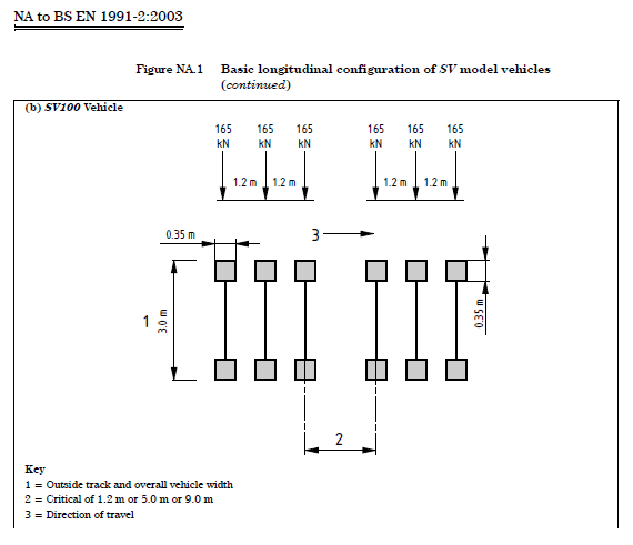
It you’re dealing with “abnormal” vehicle loading, eg. vehicles that aren’t allowed to drive on a road, you have to consider Load Case 3 as described in the EC. Due to the size of the vehicles I am dealing with the NA says I must use SV100 vehicle loading (see below).
My question is, will this always be the most onerous case, in which case do I bother with LC1 or 2 or can I just do LC3 and call it a fish?
Answers on a postcard please…
Pack your costume
BPGC, woof.
The Civils who’ve just completed the living hell that is Cofferdam will be reciting ‘boundaries, properties, groundwater and contamination’ in cold sweats at ungodly hours. This blog will look at how groundwater has unsuspectedly given life to what was assessed to be the biggest risk on my project – the rate of tunnelling.
JHG bid on the AMSP (Amaroo Main Sewer Project) expecting groundwater inflow levels to be in the region of those described in the GDR, or not a million miles off anyway. The GDR is the designer’s interpretation of the factual data gathered from the site investigation, considered relevant to constructing the asset i.e. a 7.8km long sewer system above and below the water table at depths of up to 22m.
JHG risk register
JHG assessed the rate of tunnelling to be the biggest risk of the project with a risk value of $2,660,000 ($10,640,000.00 impact x 25% likelihood). The thought process was that the risk lay in tunnelling through fine grained material (clay) with floaters (basalt boulders) in the northern end of the project alignment. There was no mention of water (impacting tunnelling rate) which has a risk value of $150,000 ($300,000.00 impact x 50% likelihood), just 1/17th of the rate of tunnelling risk. It was soon clear during shaft excavation that groundwater inflows were far in excess of those anticipated based on the information in the GDR, and the shaft excavation (and hence TBM) programme had to be amended to keep water inflows at manageable levels.
JHG engaged a specialist subcontractor to conduct a groundwater investigation regime in an effort to determine just how much water they would encounter, and to transfer the cost risk of groundwater management to the Client by proving a compensation event. In order to do this, JHG needs to show a material difference between the designer’s groundwater inflow estimates and the engaged subcontractor’s estimates. The Client then needs to accept that the level of groundwater as an unforeseen ground circumstance (Latent condition in Aussie lingo). Both the designer and the engaged subcontractors’ reports stated their estimates could be under or overestimated by an order of magnitude. Convenient considering their estimates differ by about just that.
How did we find ourselves in this mess?
Tight market conditions may have persuaded JHG to bid on a project that other tier 1 contractors shied away from due to their interpretation of the risks associated with groundwater management. It may be that it was not possible to price all the risk into the bid if JHG was to be a serious contender, and that JHG was willing to accept the risk on a construct-only contract. It may also be that JHG assumed a Trade Waste Agreement (TWA) would allow 4ML to be disposed of into an existing sewer at the southern end of the alignment at no charge (the TWA limit is in fact 1.2ML). It could be that the risk register was just a revamped version of the one used by the same project team on a recent tunnelling job of similar scope in Queensland where water was not an issue. Or it may just be that JHG accepted the GDR as gospel truth and rolled the dice hoping they could save on doing an independent investigation. In any case, the risk now requires urgent management.
Back to the site investigation
It was known at the tender stage that the ground varies from fresh to extremely weathered basalt and residual soils. In contrast to homogenous soils where permeability can be estimated through laboratory testing, groundwater in rock masses flows through fractures and joint sets. Estimating permeability in a rock mass is impossible without in-situ testing. One could argue that a tier 1 company such as JHG should have had geotechnical engineers sufficiently competent to know that, and insisted on conducting an independent SI to make better informed decisions when compiling the R&O register. I suspect the cost of doing so would have prevented this if it had happened. Hindsight is 20/20 vision.
Walk-over survey
You will remember that a site investigation is comprised of a desktop study, ground investigation and site walk-over. JHG spent $293,536.04 on the specialist subcontractor. This may well have been reduced (or eliminated) if JHG had done a little research of their own for less than the price of a NAAFI watch. A google map study screams water to the north of the project alignment (Springs Road, Donny “Brook”, the presence of numerous farm dams) (Figure 1). A drive around the local area also gave a clue (Donnybrook Mineral Springs road sign) (Figure 2). The similarity of this situation to Rich Phillips’ project in Southampton is uncanny – time spent in Recce…
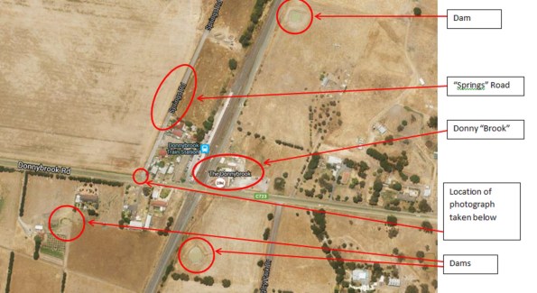
Figure 1. Google map study of the northern part of the alignment.
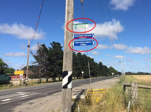
Figure 2. Road signs at the junction circled in Figure 1.
Conclusion
There could be a number of reasons why JHG accepted the risk of groundwater. A walk-over survey would have alerted them to the fact that the risk impact ($$$) was likely to be insufficient, and probability was more like 100%. The interesting part is that the TBMs cannot proceed without shafts, and shafts cannot proceed without a water management plan. To those who are soon to go onto Phase 2, line items in a risk assessment should not be assumed as existing in isolation. In this case, I like to think of it as the Jack Russell (groundwater) has woken up the Rottweiler (tunnelling rate) and they are about to bite someone on the………….ankle.
PS If anyone wants info on Melbourne, my e-mail address is daryn.mullen@gmail.com. Happy to answer any questions to do with nice areas to live in or bogan areas to avoid etc.
Diffuser Selection
Initial task
As mentioned last week I’m currently being asked to look at two projects, a Biopharm for GlaxoSmith Kline (GSK) and the re-fit of some steam plant at the London School of Hygiene and Tropical Medicine. I get the impression that Bryden Wood were hoping to initially fill my time with the steam plant project, however, I won’t be able to get involved with this until Wed at the earliest. Therefore I’m having a bit of a slow start, which is no bad thing after the last few months on site. My task to date has been to look at possible diffuser solutions (air supply) in a number of rooms in the Biopharm facility, which will ultimately feed into the specification for the main contractor. I’ll start with a few paragraphs stolen from the GSK website:
Firstly what are Biopharmaceuticals?
Biopharmaceutical products are medicines engineered by scientists and manufactured by living organisms to treat specific ailments. Biopharmaceuticals often target specific cellular functions and tend to be more potent than chemically synthesised pharmaceuticals. Today, 16% of all pharmaceuticals are biologic in nature – treating a wide range of disease areas.
What does Biopharmaceutical Manufacturing involve?
All biopharmaceuticals are manufactured in the same way. Closed, controlled reactors cultivate cells or organisms to produce large quantities of the medicinal product. During cultivation, the reactors are fed with nutrients and its temperature, pH, and aeration are controlled.
Once enough of the product has been produced, the reactor contents are harvested.
Further processing isolates, purifies, and stabilizes the bulk product. It is frozen and stored until formulation and dispensing into its final dosage form used by our patients.
To keep production free from unintended contamination by naturally occurring microbes, manufacture is mostly executed in closed, clean, and sterile equipment. Cleanroom facilities and personnel gowning (similar to hospital operating theatres) provide additional assurance of product quality.

GMP classifications in terms of allowable particle numbers and size per metre cubed. See paragraph below.
What impact does this have on MEP?
It is this final paragraph leads to a requirement for varying levels of cleanliness in rooms depending on their use. The specification for cleanliness is via a standard called Good Manufacturing Practice (GMP).
The rooms I am looking at require a GMP classification of either C or D. This is achieved by increasing the number of air changes per hour (ACH) to a minimum of 10 for class D rooms and 20 for class C rooms. Additionally specific bag filters are use in the Air Handling Units (AHUs) and HEPA filters inserted into the system (see Fran’s blog on ductwork testing).
What’s the problem / why have I got involved?
The strategy for meeting the ventilation requirements in the class D rooms is for high level supply and extract. Unfortunately there doesn’t appear to be enough ceiling space to achieve this; the reactors that cultivate cells are fed by pipework from above, in addition the ceiling is up to 5m high in places and the lighting is being supplied with LEDs, which leads to large emitter arrays being required. The knock on of this is that there is little space for both supply diffusers and extract grilles in the ceiling. We are therefore looking to provide high level supply and low level extract.
My task has been firstly to look at what diffuser options meet our requirement. I approached this in the following manner:
- Identify what the air velocity requirements are for the clean rooms – .15 m/s to .45 m/s for class D rooms. (CIBSE guide B)
- Use the ACH values and room volumes to work out what the required room air flow rates were. The assumption was made that the GMP requirement would be in excess of the heating / cooling requirement.
- Use manufacturer’s data sheets to narrow down the number of products that meet our requirement (figure 1 and 2). The main driver for this was the “throw”. Where throw is the distance from a diffuser to where the velocity of the air jet drops to 0.5 m/s. The throw that is achievable for a given diffuser will predominantly depend on its design, its use (heating, cooling or ventilation) and the flow rate of air through it. Most manufacturer’s don’t give a distance for “throw” in their data sheets, but do give a distance to the 0.2 m/s isovel (line of constant velocity), which is actually more use in my circumstance.
- A secondary consideration was ensuring that the noise rating of the diffuser was acceptable along with the pressure drop across the diffuser.
This has allowed me to scope a couple of potential solutions. I am now in the process of approaching suppliers to confirm the type of diffuser and suggested layouts. We’ll then be able to put this back into our model to see how it impacts other services and eventually write it into the specification.
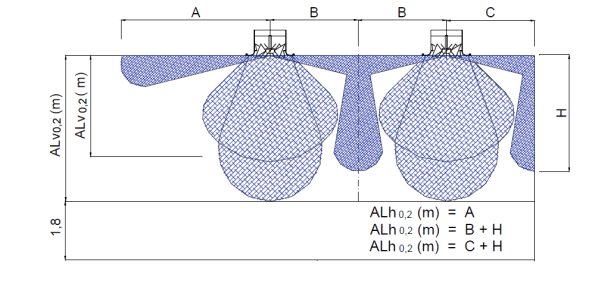
Figure 1. This figure is taken from a manufacturer’s guide and shows both the vertical and horizontal at a distance where the jet velocity has dropped to .2 m/s. The darker blue cloud indicates how the air jet would move when the diffuser is set up for isothermal or cooling conditions and the coanda effect is being utilised. The lighter colour bubbles indicate the blades in the diffuser being at a steeper angle to force warm air down into the occupied space. My room is 5m high and has 3m between diffusers, therefore ALv is 5m and ALh is 6.5m (the occupied zone is to the floor as the requirement is for cleanliness as opposed to the 1.8m indicated above for someone standing).
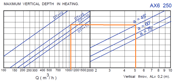
Figure 2. From figure 1 it is possible to calculate ALv and ALh. In my case ALv is 5m. I’ve used this with a blade angle of 45 degrees and a heating delta t of 5 degrees to calculate that one AX6 250 diffuser would need to be pushing through just over 1000 m cubed per hour to meet these conditions. This is then checked against the capability of the diffuser to see if it works, if it doesn’t either the blade angle can be changed or another diffuser has to be selected.
The next stage is to try and work out the low level return will work; part of the design brief is that GSK want the facility to conjure images of “ the Google of Pharmaceuticals” and for the process to be transparent. This is resulting in most of the internal walls being glass – not entirely sure how we’re going to turn glass walls into return plenum’s.
Leaky Pipes
The main fun last week was that the boilers in FtIG shutdown unexpectedly. The contractor has left site temporarily making things more difficult. The issue is not yet resolved so I will blog it when further progressed. In lieu of that excitement here is a thought on sustainability/serviceability.
After the shutdowns of the dual temperature distribution piping from my mechanical room in FtIG we noticed that significant quantities of make up water are required to return the system to pressure; this means that there is a leak somewhere. To do my bit for sustainability I mentioned this to the client and was met by little in the way of enthusiasm.
Replacing the pipe work had initially been part of the scope of the project but as there was no cost benefit attached to it this element was removed to improve the pay back period of the project. This is because the project was funded based on energy conservancy it had to have a 10 year pay back period. The client that the pipes were leaking however didn’t attach a cost to this.
The cost is inconsequential now but for the opportunity to exercise my calculator I have had a stab at it. I conducted a test on site to work out the leakage rate before plunging into a heat loss calculation.
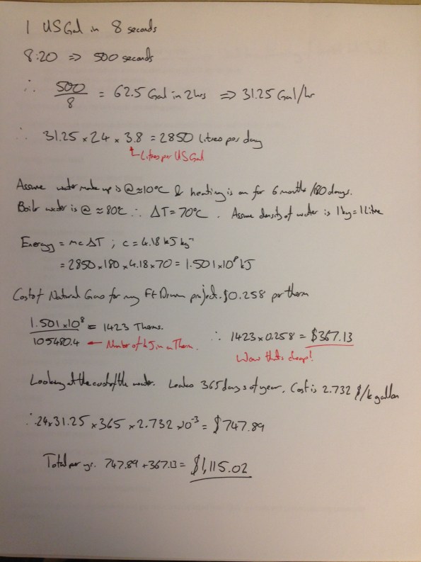
I shut off the pumps and make up water valve and left the system to rest. The static pressure was initially 10psi. To get a representative flow rate for the make up water I used the local tap off to fill a 1 gallon jug, this took on average 8 seconds.
After 2 hours I opened the make up water valve again and timed how long it took to refill the system. By now there was plenty of air in the system from the leaks and so once the valve stopped gushing I restarted the pumps to cycle the system through the air separator with the make up water valve closed to remove the air and ensure the pressure rebuilt to 10 psi. I repeated this process 3 further times until the system balanced. The time on the stopwatch for the make up water valve being open was 8:20. So
This method is clearly riddled with errors, for a start:
- Water leaking whilst I was refilling the system.
- Stop watch error.
- A static condition is not the same as when the system is operating.
- How representative the local tap flow rate test was to the flow rate of the system when nearing 10psi.
- The exact cost of energy and water; I used some figures from Ft Drum. I did an initial calculation using my electricity cost, this came out at $5,400 a year!
However the discussion has to start somewhere and some data, even with a large error value, is better than none.
Either way, had this test been done a few years ago it might have added $11,000 to the budget (or $12,500 if accounting for 2.5% inflation), which might have brought the system within the payback period. I have tried chasing down some of the early paperwork but to no avail.
More pressingly, we are due to treat the system with chemical to preserve the inside of the pipework. The contract calls for testing and topping up the system every month At 31.25 gal/hr the lost water rate is 31.25 x 24 x 30 = 22,500 gallons a month. I don’t know the exact size of the system but assuming 2000′ of 4″ pipework it would be 1300 gallons, which is about 2 days work for our leak. Therefore the contractor will be paying to completely re treat the system each month, significant quantities of chemical will be released into the ground and the treatment of the system will be totally ineffective in preventing corrosion.
I continue to beat my head against the proverbial brick wall on this one…
Welcome to Phase 3
So after a nice period of leave (Iceland is a great holiday destination!) I am now in a design office.
I’ve been given two projects to get me started: designing a crossing point for quarry vehicles to get over a high pressure gas pipeline, and designing a drainage solution to a flooded National Grid site. Additionally I’m also getting pulled into a job designing a new facility for the Somalian SF next to Mogadishu airport, not too dissimilar to one I did for our SF in Lash just before it shut. So plenty to get stuck into.
Both of these jobs were sold to me as “nice simple ones to get started with”. Which it turns out is not true for either. The drainage job requires applying for a Section 50 licence to dig up a road and a discharge consent from the environment agency. The design itself is pretty straight forward but the hoops you need to just through are not.
The pipeline crossings job is more of a design headache as what I was told was gravel is in fact clay. Despite three different surveys being conducted, at no point did anyone do an SPT, or lab testing and so no Geo properties, ground water data or test results are available. So the first step is to get a “proper” site investigation done.
Additionally the company I am attached to (WYG – a fairly holistic medium sixed engineering consultancy) do the obvious structural, civil, mechanical and electrical design work, but they also do planning, transport, force protection, international development and aid work to name a few. So the plan seems to be for me to do about four months in the Civils/Structural design dept. (overuse of the work dept. – there are three of us in the London office) then a month in any three other depts. of my choice. I’m thinking International development, Project Management and Adjudication, but I’d be happy to get suggestions!
Departure from Battersea Power Station Phase One
On Friday I handed in my PPE, laptop and called time on my secondment with Carillion at Battersea Power Station Phase One. If I’m honest this brought about mixed emotions. If you’d asked me two months ago how I thought I’d feel, I’m confident the answer would have been, “elated.” At the time I was at a bit of a low point on the project and constantly frustrated with not being able to progress works in the manner I’d like. However, over the last couple of months things have improved and there’s been visible progress in the basement, which now means that I’m almost a bit sad to be leaving.
During my time at Battersea the building has moved from a structure that was only a few levels tall in most places, to one that is topped out bar two cores. In my opinion it now looks pretty dominating if you travel into Victoria on the train or walk west along the river from Waterloo. The structure moving up has allowed the basement to open up – back propping has been removed and water ingress issues have been mitigated (to an extent) which have removed many of the frictions of trying to work in the basement.
When I arrived on site MEP activity in the basement was revolved around the installation of pipework and containment. I thought I’d be involved in the installation of an energy centre and variations to external works; however, neither of these activities has started yet. As I left site I was working in 6 of 9 thermal plant rooms, 62 of 89 modules containing 300mm dia pipework had been installed, and 4 of 12 TX rooms were in progress. I’d hoped to see the filling and flushing of core A (programme date Aug, revised date Oct), but this was still someway off when I left.
I believe my attachment has been as success, having gathered experience in competencies A1, C1, C2, D1, D2, D3 and E2, E3. Awaiting confirmation from AER3 my focus for phase 3 will now be on A2, B1,B2,B3, and E4.
Is there anything I wish I’d done differently? Not hugely. I believe I’ve got the best out of what was available at Battersea. In an ideal world my attachment would have started and ended 3 months later which would have opened up more interesting MEP work. In addition I would have benefited from there being more Carillion mangers working in the basement area – part of the reason that things picked up in the last few months was that the structures team put an additional project manager in the basement to progress their works. Perhaps I should have seen this as an opportunity earlier on, but I didn’t see it within my remit and would have probably been getting out of my lane trying to manage the detail of ground workers, sheet pile and concrete subcontractors. I’ve also not touched on the tender process whilst at Battersea as the MEP side of the job has been beyond this. On reflection this could have been overcome by working on another Carillion job for a day week or a short period (something my boss suggested during my wash up interview). Although I’m not sure this would have worked in reality due to the pace of life at Battersea – probably why it was suggested during my final interview if I’m being cynical. Something for phase 1’s to bear in mind though as they head out on phase 2.
Would I do this job outside the Army? Probably not, although, I will bear in mind the fact that everyone has re-iterated to me, “Battersea is not like any job they’ve worked on before”. That being said the people have been great to work with, the atmosphere is similar to that in a Troop / Squadron and at the moment the money is good; I am not being replaced at Battersea, which is due to the fact Carillion’s prelims are tight and the people who’ve recently been interviewed to join the MEP team are asking for circa £85k plus package. Carillion will try and bridge the gap until someone else from the RSME arrives, however, I imagine at some point something will give and Carillion will decide to pay something close to the market rate to get someone else on board the team.
I’m now working at Bryden Wood Group for phase 3 within the Mechanical team. There are currently two projects I will be involved in. The first is a Biopharm in Ulverston (making Pharmaceuticals that are biological in nature), which will be the first of its kind for GlaxoSmithKline in the UK . This project is in the concept stage and valued somewhere between £100 to £150M. The second is steam plant at a London University which is only valued at £50K from a MEP design perspective, so hopefully lots of scope for me to get a lot of autonomy.
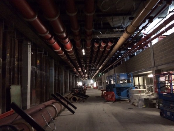
Installation of Raceway modules progressing well. The four pipes on the left hand side at high level are CHW and LTHW F&R. These came to site on modules like the one that can be seen on the ground. Then there is more LTHW & CHW pipework which was installed loose, gas and public health.
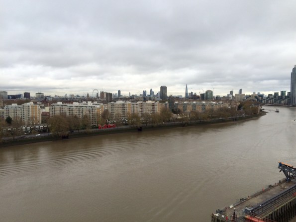
The view £15M will buy you. Looking out over London from the penthouse in core A. To the left of the picture is the main railway line into Victoria so a double bonus if the owner happens to be a train enthusiast.
