Archive
Shear and UPL
Shear and UPL
This is not what I am doing but a technical problem has popped up on a site one of the members of my team oversees and I thought it was interesting.
Imagine a secant wall in a rectangular formation with an in situ basement box to be poured inside it – see below.
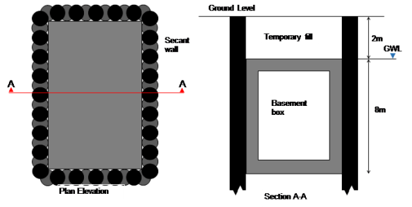
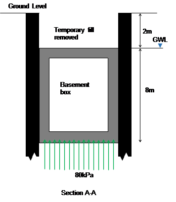
The base of the box is at 10m below ground level and the water level is at 2m below ground level. Over time as water pressures return this creates an uplift stress of 80kpa. Assuming the base and walls have a downward stress of about 60kPa this leaves a remaining 20kPa downwards stress needed. When the fill is placed above the box this results in a net downwards pressure (bulk weight of soil (20kPa multiplied by 2m gives sufficient resistance). However, let us assume that the fill gets removed for a subsequent development (as is planned).
The risk is uplift failure (UPL), I.e. the box tries to move to the surface because of the buoyancy effects.
The solution.
Dowel bars (yellow) between the male secant piles and the internal box provide shear resistance (green arrows) to stop the box lifting up.
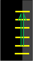
Dowel bars fixed between piles (black) and inner box (grey)
The problem
Suppose over time water is able to get between the secant wall and new basement box. Over a bit more time the gap between the secant wall and box might increase a bit more. So the dowel bars now act in tension between the secant wall and hydrostatic head (blue) pushing the box inwards. Over more time still and the dowel bars act in tension due to the lateral force (horizontal green arrows) applied by the hydrostatic head which makes them strain, or elongate, and therefore have a slightly reduced shear capacity.
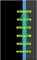
Tension in dowel bars created by hydrostatic head, dowel bars strain (extend).
An 8m depth of water implies 80kPa or 80kN if the dowel bar resists one metre square (for simplicity). E=(F/A)/(ext/original length). Ext/orig=(80/pi d2/4)/E, E (210GPa), d =40mm, implies 0.2mm/600mm multiplied by E (210GPa) equals 70MPa axial stress.
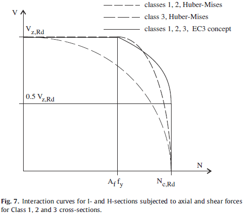
Remembering back to EC3 days or Von Mises, as axial force increases, shear decreases. Therefore this increase in stress in axial force (N) may reduce shear (V) to below the design capacity – Vz Rd reduces as axial force increases.
The question is why does the reinforcement bar extend by 0.2mm? The design specified a plain bar, the contractor installed a normal ribbed reinforcement bar into the secant wall which would generate tension between the secant wall and inner box as the hydrostatic head builds. A smooth bar would also lateral movement without reduction in shear capacity.
The problem is worsened when uplift occurs because the rebar it put into bending and therefore undergoes further reduction in capacity. See the 3D graph below where moment reduces capacity even more.

The solution (2)
Install a sleeve over the rebar thus removing the interlock effect of the ribs on the inner wall. This allows lateral movement of the dowel bars to avoid any axial force. Uplift is ten resisted by the dowel bars as planned in the design!
Summary
Clearly there are a number of assumptions and simplifications in this blog (basement box would also resist some lateral force reducing movement, soil type ignored, move to drained approach). I thought this issue was seemingly minor, but with an accumulation of risks (tri-axial forces) the consequences could be high. I would argue the likelihood of the risk arising is low but having specified a design solution to a complex problem, Arup was not going to reverse its view (with full finite element analysis to back up assertions) just to hurry the job along.
Snowmageddon
In case you’ve been living under a rock for the last week you’ve probably heard that the East Coast of the US has had some snow. The fervor of the media attention has been comparable with the chance of a dusting in London. We have had about 2 ft so the panic is perhaps a little more justified. In contrast this is considered normal in places such as the mid-west so why is it an issue for the D.C./Baltimore region.
Like most things I suppose it all comes down to risk as the area doesn’t get snow in these quantities it is not as prepared for the volume as other areas. Looking from a Facilities Management/Design Planning perspective I note a couple of things. We design drainage for 100 year rain events but also should think of the snow equivalent:
- Where to put it. Snow takes up quite a lot of space. You can compress it, but only so far. So what? In our condo there are, or should I say were, some outside parking spaces for visitors. Large grass verges have also been optimized, alongside peoples’ front gardens; any grass area is now a snow store. Also side walks, clearly Americans don’t walk so they are considered fair game.
- How to move it. Shoveling 2ft deep snow out of a driveway manually must be hard work; I can see why people died. Snow blowers are awesome for pathways and you could probably do a short road with determination and planning. Snow ploughs are a given. But the rate limiting step seems to be wheeled loading shovels or skid steer loaders. These have the capability of both heaping the snow higher and of moving it around in a more deliberate fashion than just pushing it to the end of a run. In the middle of the city dump trucks have been used to transport snow out of the narrow residential streets.
- Don’t wait for the end. 2ft of snow is difficult to manage, far easier is 1ft of snow twice. This keeps essential lines of communication open, gets everything open quicker and means that smaller equipment isn’t overwhelmed, therefore a broader range of equipment is useful.
- Drainage plans; three things on this.
- Firstly, knowing where the drains are so that they can be cleared to allow the snow melt in, by either marking them with wands, having a site plan of them or both.
- Secondly, putting drains, close to but not in the middle of the forecast snow collection areas. Close to so that there is not a long stream of water to freeze overnight, but not underneath so water can actually get down the drains. This hasn’t been done so well where I live.
- Finally, and another one that isn’t so great in our condo, is making sure there is actually a fall to a drain. I’ll leave that one as it is.
- Finally communication seems to be pretty key. I could talk about American authoritarianism but I would be descending down a slippery slope towards ranting there.
Obviously the whole experience has been harrowing being locked in with only the TMR 4 deadline for company and in no way did we get any skiing or any fun in at all.
Struggling to Post!?
About to leave PEW and need to be able to post? Try…go into any post and look to the top left corner “My Site”
Go down and click on posts – new post
Rest is very simple…
Tips from the field anyone?
Port Augusta to Melbourne
Prior to Christmas I moved from the Sundrop Farm site in Port Augusta to Melbourne where I am now doing my design placement with KBR. This blog summarises the progress on site prior to my move and initial projects on the design placement.
My packages of work on site had more or less come to a close by the time I left. The lining of the lagoons and the installation of the freshwater lagoon cover were complete with only commissioning remaining. The three pump stations were all practically complete, with only snag list items remaining. Ideally I would have liked to have seen this through, but inevitably this wasn’t to be. Despite my personal work packages drawing to a close, pace on site continued to accelerate as the end of the year approached. The reason behind this were linked to a drive to get the solar tower erected prior to Christmas, which enabled JH to claim more in the final progress claim of the year. As I left the project was at the 50% complete stage.

The Solar Field – beginning to look complete
With this increase in pace I ended up picking a few packages, these included: getting the tower crane foundations in place, ensuring the solar tower foundation was prepared for the first tower section, installing the pipe rack and getting the foundations in for all the mechanical plant. Everything fell into place eventually but needless to say there was a lot of coordination required, as all these activities were on the critical path and in the same 50m². The whole solar energy system is a bit of a nightmare to be honest. The primary subcontractor involved was Aalbrog Concentred Solar Power (AAL), who were on a supply only contract. The package had been tendered as a concept design and as construction progressed it was clear the level of detail in the design was poor. There were numerous design changes after the construction had begun and as I left there were still too many unknowns for JH to put out the mechanical package to tender and expect to get a reasonable price back. In the end they made the call to use a JH workforce and run the package themselves. As I was leaving the estimate was that the mechanical installation package would be at least $3million over budget. The reason for this were various, but main errors include missing the cost for the heat shield on top of the tower out of the initial budget and budgeting only $6000 for the tower fit out, when it is actually costing almost $1 million. The reasons for these omissions are again various but a lack of knowledge about the concept design and assumptions about the AAL scope of work appear to be the main causes.
Anyway the solar tower was erected prior to Christmas as planned and now they are waiting for the top module to be finished so that it can be lifted on top. Off the top of my head it is costing $100,000 a day for the crane to be stood there!

Solar Tower – Top module still to go.
Design Phase
I have been in the design office for two weeks now. Work wise it has been a little slow, as KBR where not expecting me and there are a number of packages of work that are out at tender with the results due this week. I am based in the water group in the KBR office in Melbourne. Most of the work the group does falls under what is known as the Joint Venture (JV) with John Holland and is for Melbourne Water. All of the projects are design and construct. So far I have found myself working on the following:
- An Odour Treatment Facility (OTF) at the entrance to one of the main waste water treatment sites in Melbourne. The design of the facility is just getting to the detailed phase and I have been involved with the HAZOP process. The concept is pretty simple, foul air is drawn out of the sewer and though a filter which contains a bio media which feeds on the volatile organic compounds (VOCs), ammonia, hydrogen sulphide (H2S) and sulphur compounds, thus removing the odour. The budget for the whole project is $7.3 million.
- The second is a project is a Sodium Hypochlorite (NaClO) dosing system at the Greenvale Reservoir. The site currently uses chlorine gas but residential encroachment in the area and with additional water demands this is now deemed to be insufficient. The total project budget is $3.5 million. So far I have been involved with reviewing the P&IDs, conducting some pump calculations and am now beginning to write specifications for the associated instrumentation and plant. I am also leading with the design of the HVAC design for the new building that will house the dosing system.
- The third project I have only just begun working on today. It involves writing the technical specification for a waste water treatment facility that is treating the leachate from a landfill site. Previously this was stored on site and driven away by tankers. The operators want to reduce cost by treating on site before feeding into the sewer system. The earth works and main pipeline are now complete and KBR are going to put the mechanical and electrical install out to tender. The idea is that the technical specification will form part of the tender pack.


The Building Built By Gurkhas
This blog doesn’t focus on my experiences, but is a quick summary of other work being conducted by BWL. If you’re interested in pre-fabrication of or Gurkhas it may be worth a read. The work that I’m going to quickly talk about is the design, manufacture and construction of a pharmaceutical factory in a box. This has recently been written about in February’s issue of the Construction Manager. I don’t have a link, but I do have a scanned copy of the article if anyone would like it.
There is a growing demand for pharmaceuticals in the developing world. Previously issues surrounding the supply chain and skilled workers in developing countries had made constructing high-specification buildings such as pharmaceuticals factories difficult. Therefore GSK as the client and BWL as the consultant have come up with a system that has allowed a facility to be built at 30% of the cost of a traditional approach and in four weeks rather than 12 using a team of just 8 ex-Gurkhas.
The factory comes pre-packaged in iso-containers and is packed in such a way that the first item you remove is the first item that is needed. The building looks to be a steel portal frame with the factory then sitting inside this structure. There’s no mention in the article about pre-ceding ground work requirement, but how difficult is that? The factory includes details like the roof of the frame coming flat and then being able to pivot about the apex and be locked into position to avoid working at height. Likewise the factory internal roof is constructed at low level, services added and then elevated to the appropriate height using block and tackle. Connections between components are made with simple bolted connects that are colour coded to ensure the correct bits are put together.
All in all it looks very innovative project that has wider reaching applications. The significant element of doubt I have about this is that it was completed by Gurkhas. When people have discussed this in the office with me they’ve implied BWL and GSK used Gurkhas because they’re representative of the workforce that you might find overseas. Nobody seemed to be aware of the rigorous selection process that is required to become a Gurkha and therefore your probably dealing with someone who is brighter than the average. Also the article makes reference to the fact the workforce had some plumbing, electrical and decorating experience. Not sure if that means they were ex-Gurkha Engineers or not.

A screen shot from the simulated build sequence showing trusses being moved into position.
London School of Hygiene and Tropical Medicine Update
As previously mentioned one of the projects I am involved with at Bryden Wood Limited (BWL) is the replacement of steam plant at the London School of Hygiene and Tropical Medicine (LSHTM). This blog is a long overdue update on the project, which aims to give background information and highlight what I’ve been doing.
The project
The LSHTM currently has two steam generators that are sized to produce 1300kg /hr of steam at 10 Bar g (g denotes gauge pressure). Steam within the building is mainly used for autoclaves (units you put kit in for sterilisation) and a couple of air handling units (AHUs) although the current generators are also linked to a district heating system and provide redundancy for an element of the school’s heating system. The generators are located in a sub-basement and distribute steam up two risers to serve the loads in the building. The LSHTM was originally shaped like a capital A. Extensions to the building have seen the two hollow sections within the building filled in. This is leading to insufficient ventilation reaching the plant room where the steam generators are, resulting in the building overheating. Analysis of the use of steam within the building has identified that it is no longer required to supply the district heating system and will only be used as a back-up heating supply in extremis. Therefore maximum steam demand is 520 kg /hr.
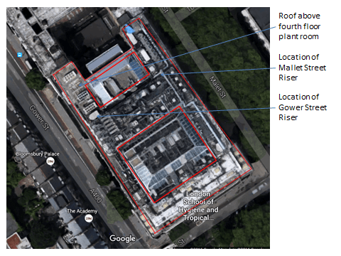
Aerial view of LSHTM. The red line demotes the outline of the building which used to form a capital A shape. The two hollow sections of the building have now been filled in.
The client, LSHTM, therefore wishes to install two new, appropriately sized boilers at fourth floor level and take steam back down the building to serve various loads. The existing system will stay in use and only be stripped out once the new system is fully online. This will require a period of gradual handover from systems as individual loads are brought online. The project is valued at £1M and the consultancy fee is a fairly small £50K.
The BWL team looking at this project is 3 strong; a director who effectively brought the job to BWL when he moved company, myself as the mechanical lead and an electrical engineer. The project is mainly mechanical in nature and the director is keen to take a hands-off approach, so I’ve essentially got a huge degree of responsibility and autonomy on the project which is great.
Steam
Before I go any further it’s probably worth explaining a bit about steam, although I won’t fully explain all the concepts this will end up like War & Peace. The following link is very useful and informative if you get involved with steam design at all or want more information:
http://www.spiraxsarco.com/Resources/Pages/steam-engineering-tutorials.aspx
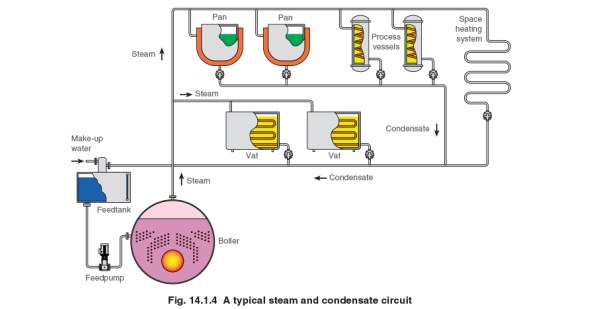
In normal mechanical systems it is usual to see a flow and return pipe. This is the case when dealing with steam except that the flow pipe contains your steam, which is dry saturated steam (steam that has had energy added to it so that it is completely dry) and the return contains something called condensate. Condensate is generated when the dry steam is subject to a change that allows it to change state to a wet steam of liquid. This change in state can either be caused by a drop in pressure or temperature. The change in state can be deliberate – the steam is being used in a processs e.g. through a heat exchanger or unwanted, e.g steam running along a pipe cools and condensate is generated due to the loss in energy. What we don’t want to happen is for condensate to build up in steam lines (impacts the performance of heat exchanges, is corrosive and can lead to water hammer damage), therefore condensate is removed using something called a steam trap. We also don’t want to waster condensate if possible as it still has energy within it which we can reuse at the boiler / generator and is valuable in that water going into a boiler needs to be treated. Reducing the amount of new water required by recirculating condensate reduces costs massively.

What have I done to date?
I’ve surveyed the site and produced a basic REVIT model of the plant room that we need to put the new boilers. In conducting my surveys I’ve also identified that one of the AHUs being served by steam isn’t utilising the steam (valves isolated and pipes cold), I’ve since spoken to the facilities manager who has confirmed this has been the case for two years. This has allowed me to removed the AHUs from the steam load profile a saving that allows me to drop down a model size on the boiler and save the project up to £50k – not bad for just having a walk around. I’ve just pulled together and submitted a Pre-Qualification Questionnaire and mini-tender document for the purchase of the steam boilers which goes a long way to filling the short falls in my C competencies from phase 2. Next stage is to move onto a bit more detailed design and start sizing pipes.
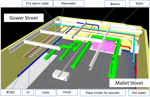
Basic REVIT model exported to NAVISWORKS to show the constraints within the fourth floor plant room.
View within the fourth floor plant room where the new steam plant will go (denoted by the blue square).

View within one of the existing risers. This is the better set out of the two, the other looks like someone has just thrown pipes and wires in. There appears to have been plenty of expansion over the years but not stripping out. There are also no as built drawings or schematics, which when services are incorrectly labelled makes coming up with a plan interesting.
Oz NDY – Vetwest Animal Hospital.
Introduction
Introduced previously is my current short-term project; designing a fitout for a Vetwest animal hospital. This is my first project as a Project Leader (PL), essentially project managing from start to finish. Before leave I/we submitted a concept design solution for review by our client, the managing contractor, Perth Citi Fitout (PCF) and their client, the building occupier, Vetwest. This blog discusses the on-going project and challenges.
Concept Solution Review
Reading my first client email correspondence, with reference to the concept design, I am already sensing the commercial challenges of the client facing side of design consultancy. PCF are concerned about changes we have made from their initial thoughts, particularly referring to the mechanical design of the air-conditioning (A/C) system. This is because we have included additional equipment which will increase their costs and eat into their profit margin. Without seeing the contract between Vetwest and PCF it’s hard to know if PCF are on a fixed price contract or not. I think they are as indicated by the technical data sheets they supplied us for the air conditioning units, which included a supplier quote of AUD $55k for 3 x Daikin split DX Variable Refrigerant Volume/Variable Refrigerant Flow (VRV/VRF) units.
Our concept design suggested 4 x packaged units costing circa AUD $70 – 100k. This was based on the layout split into four zones and included a dedicated unit for the HEPA filter in the surgery room. Packaged units aid in mitigating operational interruptions for maintenance as they will all be roof mounted. But PCF’s proposed split DX units would mean the indoor unit being located in the ceiling void which would disrupt operational use, including treatment/surgical operations. There are also other benefits of using packaged units but PCF, with confirmation from Vetwest, want to keep the costs down. That’s absolutely their prerogative but our view is split DX units are more suited to domestic buildings rather than commercial.
Although not our contractual duty, we feel we must look out for the interests of Vetwest and provide a design solution to their requirements, especially as they are seeking Australian Veterinary Association (AVA) hospital accreditation. This will indirectly aid PCF because if they fail to deliver the scope of works in accordance with Vetwest’s specification then they will become liable for variation charges.
How to manage this…
In order to tackle this I set about highlighting the benefits, via justification, of our design. Annoyingly, this information had already been submitted, written into a Consultants Advice Note (CAN). But, not wanting to simply reiterate this information, I set about giving the problem its due diligence by providing additional information which I gained from further research. This gave me the opportunity to review our design myself and pick-up on a couple of improvements that could be made. For example, the specific requirements of the Accreditation Scheme for the AVA (ASAVA) referring to the prohibition of any Air Transfer Grilles (ATG) and requiring a dedicated exhaust fan to outside the facility for the isolation room. This also included a dedicated exhaust fan and a motorised volume control damper connected up-stream of the supply air (SA) grille. This ensures the design’s ability to maintain negative pressure and if the exhaust fan should fail the SA damper can be completely closed to avoid positive pressure build-up.
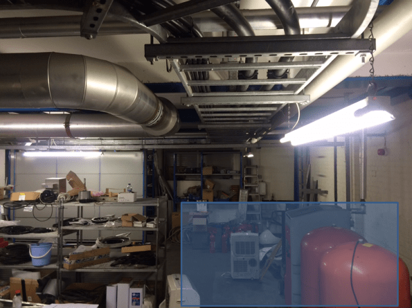
Talking this through with the Project Director (PD) we came up with a compromise and amended the concept design, see figure 1. We reduced the number of A/C units to three, utilising the split DX units PCF proposed to keep costs down, by combining the surgery room with the rooms in the purple zone. The surgery room would therefore require its own SA leg of ductwork and a dedicated inline booster fan to overcome pressure losses from the HEPA filter unit. It would also still require a dedicated exhaust fan as air from the surgery room cannot be returned to the main A/C unit.
Other changes were: combining exhausting air from the cat and kennel rooms, via linked ducting, which reduced the number of exhaust fans by one; reducing rigid ducting and replacing with flexible ducting where possible, but still in accordance with BCA guidelines where maximum lengths of flexi duct must not exceed 6m; and; designing in two options for drainage, one using bucket and floor waste traps, the other a grease trap. This was TBC by Vetwest as to the outcome of their application to Water Corp for a trade waste permit. Ideally this should have been done before so we knew the exact requirements for which we are being asked to design to rather than us having to suggest multiple solutions.
I also drew-up three hydraulic concept designs for: hot and cold water, oxygen and suction, and drainage.
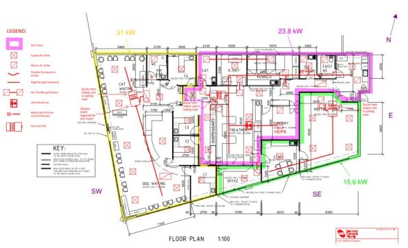
Figure 1. Revised Mech Concept Design.
Next steps
These changes were submitted to PCF and Vetwest for review and I am awaiting their feedback. Vetwest physically gain access to the building on the 1 Feb so is the earliest any on-site works can commence. Therefore, once the concept design has been approved and frozen (hopefully in the next two days) we have said we can complete final detailed design two weeks from then. So hopefully ready by the 1 Feb. In the mean time I am cracking on with software based heat load calculations so I can size the A/C units for the supplier to order in and stay inside lead times.
Heat load calculations
Figure 2 shows an example of my initial estimated heat load calculations – using the Australian Institute of Refrigeration, Air Conditioning and Heating (AIRAH) template.
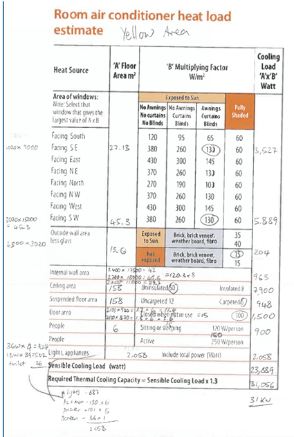
Figure 2. Estimated Heat Load Calculations for the yellow Zone.
For detailed design NDY currently use a software package called TRACE to calculate heating and cooling loads in order to aid sizing of key plant, such as, A/C units, boilers, etc. It is shortly to be superseded by an advanced programme called CAMEL; I vaguely remember Ben Foster making a pun about it when comparing it to Hevacomp. CAMEL has the added bonus of integrating its building details and input data with another software package called BEAVER. BEAVER is a building energy simulation programme which is used by the majority of building owners/occupiers to estimate: heating, cooling, fan, equipment and lighting energy consumption. However, for this project I will be using TRACE.
What did I learn?
In summary, so far – a lot! It really is just like conducting one of the projects from Phase 1, so in that respect that was perfect training. The only real difference is the standards being Australian – but then they are very similar and searching for them is the same.
Stakeholder engagement is key. We had an initial project meeting before Christmas and followed it up with a site recce. Getting stuck into the detail this past week has highlighted a number of areas that needed clarification. Therefore a number of RFIs, directed at both Vetwest and PCF, were sent, all to aid project management. The good old fashioned telephone being the preferred method, with all communications followed up in writing, be it by email or CAN.
Thames Tideway Epic induction
Thames Tideway Epic induction
I attended the Thames Tideway Induction this week. Even if Carlsberg did health and safety inductions it would not be half as good as this was. It was simply Epic, which actually stands for Employee Project Induction Centre.
The Problem
The Tideway Project approach to Health and Safety is an attempt to re-set precedence where currently major projects (such as Olympics, Cross Rail, Heathrow) tend to have an increase in RIDDOR incidents at the start of a project (as new employees get bedded in) with a peak a few months in, then a decline to a plateau and a rising spike at the end (towards handover). I think this is pretty similar to operational accidents in theatre where there was a learning period which caused injuries, then lessons are learned but by the end there is some complacency resulting in a final spike.

Graph of RIDDOR incidents – representative only and recreated from induction slide – hence magnitude of numbers removed.
Using the accident numbers from previous projects against the number of hours planned to be worked on the Tideway project would mean:
- 2 deaths
- 1500 life changing injuries
- 10,000 lost working hours
Clearly you can’t accept that (or effectively plan to kill 2 people and injury 100s more) and so the whole push from even before starting is to set the standard at high in hope that will result in a better outcome.
The induction
Tideway have rented office space next to MI6 and have created a mock up accident scenario. I’ll be light on the details in case anyone else goes through it but effectively the day starts with you in the site canteen and 2 workers arrive (taking us, the audience, by surprise). They chat about random day to day stuff. They then leave to work on site (audience follows to site). There is then an accident of one of the workers who later dies (scenario, not real). The audience then moves to another room – HSE investigation which is pretty tough for the audience too, then the flat where the employee lived (heavy play on consequences of such an event), then a room split between a site office and a head office to hear background conversations leading up to the event. Back to the canteen (to recover) and start the practical training.
The day is run by a team of actors from the Active Training Team company who role play through the scenario but then are there to re-run the scenario to talk through what the causes were and what actions might have resulted in a different outcome. This is similar to the role play equality and diversity training the Army now do but far more interactive.
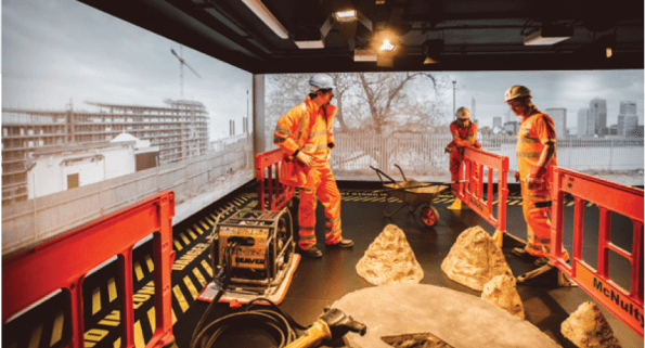
Scene from the induction centre – actors playing very convincing construction workers
The afternoon was filled with behaviour based learning – all practical group discussions which included at some stages going toe to toe with the actors on various other scenarios. The point being to learn techniques and methods for all levels of construction workers to improve their behaviour and mind-set towards health and safety.
Level of Engagement
There was one 15 minute presentation which was delivered by the CEO of Tideway (Andy Mitchell – recently on the front of NCE magazine for different reasons) of a £4bn project so it is clear where his focus is.
Methods
The health and safety approach is pretty impressive, especially if this is to be the standard that every employee (over 5000 expected) over 5 years goes through it. They have got a comprehensive approach covering worker language skills, issuing of the best PPE, lessons learned from Heathrow, Cross rail and the Olympics, 3-monthly stand downs across all sites to discuss H&S issues, and a drive to have the most secure sites with the best welfare facilities.
Will it work?
I think the recognition of the problem and desire and motivation to change history is fantastic. However the difficultly will be in getting everybody to embrace it when budgets are squeezed, timelines are reduced and concrete wagons are ready waiting on site. If the collection of parties play their roles well – designers design safe and buildable structures, contractors allow for safe working methods, invest in employee training and Tideway live up to the standards they are talking about then I see no reason why the injury levels cannot be reduced. I do not believe there is an argument for the irreducible minimum in this instance with money and time, quality (in health and safety) can be achieved.
Summary
It will be interesting to see how it plays out. There are some particularly hazardous working environments: underground, confined spaces, deep excavations and over water. The 3 sets of joint ventures (8 different contractors) will have a far more onerous task of getting people to acknowledge the risks and how to mitigate them. A balance between having to produce paperwork against the level of risk an activity possesses will have to be considered to make sure effort is best placed to achieve the desired effect. Finally, with this significant investment and change (improvement?) in mind-set to health and safety what happens if it does not work – are all major infrastructure projects doomed to kill and maim people. It is clear there is buy-in at the top and this is being pushed from the highest level so hopefully it will succeed.
CCB – Phase 3
I started to transition to phase three very shortly before Christmas leave. I factored in around 6 full days of sitting at the Baltimore City Crescent Building (CCB) split over a two week period to settle. This would allow me time to meet and greet; sort out a desk space, IT and scope out the work. Amazingly it only took around half a day to sort out IT and I had a desk space waiting for me, which I gather is at odds with Henry’s experience. For me transitioning 3-2 has been much easier than 1-2. I started full time at CCB on 4 Jan, however have retained my access cards to site so I can go and get ‘a cheeky shufty’ before departing the States.
The Structures team I am working in now sits in a different Division to the Construction Division where I was previously housed and is physically sited in the Baltimore District headquarters building in downtown Baltimore.
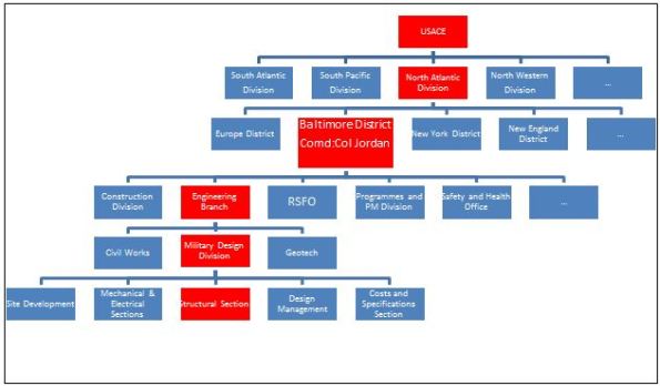
USACE Organisation
The figure above shows the organization, with red signifying where I sit. The Area Office where I was previously working was, like Henry’s, part of the Construction Division. Phase 3 sees me shift to the Military Design Division, which is a part of the Engineering Branch. Rather confusingly for a military organization the term ‘Division’ is no indicator of the position of the department in the hierarchy; Construction Division and Engineering Branch are equivalent departments, Construction Division and Military Design Division are not.
The Engineering Branch is responsible for the procurement, design and overall project management of federal and publicly funded projects. This is different to the Construction Division, who physically executes the works. Civil Works deals with levees and dams; Military Design deals with new construction and refurbishment projects; Geotech deals with geotechnical analysis, design of foundations and soil testing.
First tasks as part of the structures team include gathering an appreciation of the work available, described below, and becoming familiar with the US design codes and their application. Where opportunity and time permits I also hope to take on small portions of work from the geotechnical branch and site development (civils) team. This is fairly usual for the USACE placed students.
Below is the breakdown of what has been proposed so far.
Fort Lee Training Support Facility, Virginia. This is a $33m project which will be procured on a traditional contract with USACE conducting the design. It being undertaken by the Baltimore District, despite the site being situated geographically in the Virginia District. This is because Baltimore District has capacity whereas Virginia District does not.
The training facility requires a largely column free 120,000 sqft footprint in which various military artefacts and exhibits can be housed and moved around, depending on training requirements of the end user. As well as lecture theatres, toilets and workshops, associated with typical training facilities, there is also a requirement for an armoury, which must conform to its own set of construction standards. The training facility project could be defined as a museum, however because this would invoke more stringent, regulations and because it is not open to the public this is not the case. The requirements for humidity control and airflow are however being taken from museum standards in order to ensure the protection of some of the more delicate training aids and artefacts. The requirements for the movement of training aids, some weighing up to 90T also means that the typical reinforced concrete slab on grade (ground slab) has certain strength and ‘finished flatness’ requirements so will be designed more like a pavement, similar to runway design. It can be seen therefore that the design of the training facility allows for some freedom in the selection of which standards apply.
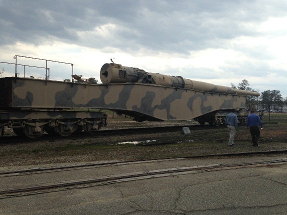
Example Training Aid
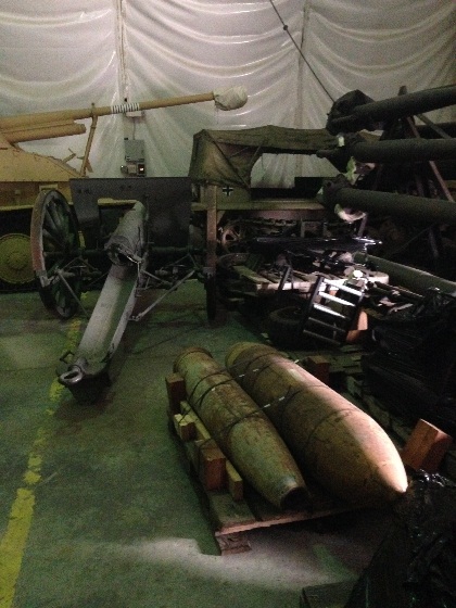
Example Training Aids
The project is at 65% review stage, however is recognised as being more like 30 – 40% complete. This is mainly due to issues with the completion of the Site Investigation (SI) and subsequent Geotechnical Design Report. This was sub-contracted out, however issues with the scope meant that the SI required completing twice as insufficient information was gathered first time around. A comprehensive GDR for the project is still forthcoming, however for the purposes of project progress assumptions have been made about the bearing capacity of the soil. This means that a large risk to the project lies in the ground conditions since design is being based on assumptions which have not been fully verified. This has the potential to increase the project costs to the client at the execution phase and highlights the importance of a sound scope for the SI in the first place.
The site itself is a forested marshy area, which has been largely created by surrounding projects, which have drained their sites into the proposed area. It slopes across the length of the project causing an 11’ elevation difference between one end of the training facility and the other. At around 30’ depth there is a thin highly compressible clay layer. This makes the project susceptible to long term continued settlement issues, in particular due to the large surcharge placed on the ground due to fill the fill required to level the site. The current design stipulates that shallow foundations should be adequate, which surprised me on hearing the outline ground conditions.
The requirement for open space means that the proposed steel construction will not be braced. Instead a steel portal frame design is chosen. Spans of up to 60’ mean that both standard and built up girders are insufficient and so a truss system has been chosen to try to maintain ‘a lighter appearance to the members.’ The sizes of the outer faces of the building mean that lateral wind loading and seismic loads are high. This means that the moment connections and details require careful consideration to ensure that lateral loads can suitably be transferred through the trusses into the columns and foundations.
My responsibilities will be to assist the lead structural engineer with verification and detailing requirements. I will also be involved with the shallow foundation design. The 95% design submission is due in June 16.
Building 8607 Renovation, Ft Meade. This is a design build project and so USACE is only required to produce the technical specifications and tender documentation on behalf of the client. Because there are Anti-Terrorism Force Protection considerations (ATFP) it is, however, likely that there will be some more focus paid to conceptual design. This may extend to some initial element sizing and direction as to which ATFP approach is suitable I have been told to get a software license for STAAD Pro to assist with a bit of modelling to test assumptions that go into the specification (so thanks NJP).
The project scope is to turn existing accommodation buildings into administrative space within the existing Ft Meade camp. The tender documentation is required to be complete by mid Jul 16. This is likely to be background work in addition to the main training facility project described previously.
Access Control Point, Ft Meade. This is a $20m project procured on a traditional contract with USACE conducting the design work. The requirement is for a fairly generic access control point to be installed at Ft Meade, consisting of several inspection lanes and indoor areas for security staff. The inspection lanes are simply steel hollow section columns with steel deck canopies spanning across the point of entry. The canopies won’t resist lateral forces and so essentially the steel columns will resist gravity and lateral forces as cantilevers. The indoor areas and inspection lanes also require to provide some element of protection for security staff and so will require design for impact and ATFP.
Other. As stated there may also be scope to grab some civils work from the Site Development team. They deal with horizontal construction such as pavement, storm water drainage etc and could be good for some additional sustainable development exposure as well as exposure to a broader range of engineering. This combined with the different structural projects which are at different stages of design should provide a fairly rounded design experience.
In Other News

Mike O’Callaghan–Pat Tillman Memorial
This…
and this.
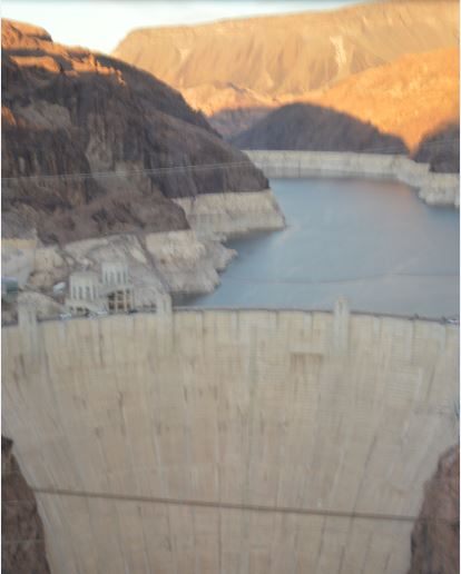
Hoover Dam
