Archive
Shear and UPL
Shear and UPL
This is not what I am doing but a technical problem has popped up on a site one of the members of my team oversees and I thought it was interesting.
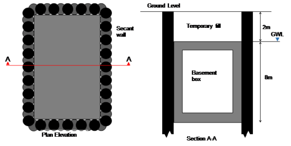
Imagine a secant wall in a rectangular formation with an in situ basement box to be poured inside it – see below.
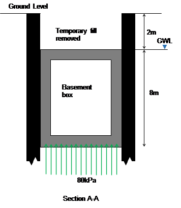
The base of the box is at 10m below ground level and the water level is at 2m below ground level. Over time as water pressures return this creates an uplift stress of 80kpa. Assuming the base and walls have a downward stress of about 60kPa this leaves a remaining 20kPa downwards stress needed. When the fill is placed above the box this results in a net downwards pressure (bulk weight of soil (20kPa multiplied by 2m gives sufficient resistance). However, let us assume that the fill gets removed for a subsequent development (as is planned).
The risk is uplift failure (UPL), I.e. the box tries to move to the surface because of the buoyancy effects.
The solution.
Dowel bars (yellow) between the male secant piles and the internal box provide shear resistance (green arrows) to stop the box lifting up.
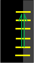
Dowel bars fixed between piles (black) and inner box (grey)
The problem
Suppose over time water is able to get between the secant wall and new basement box. Over a bit more time the gap between the secant wall and box might increase a bit more. So the dowel bars now act in tension between the secant wall and hydrostatic head (blue) pushing the box inwards. Over more time still and the dowel bars act in tension due to the lateral force (horizontal green arrows) applied by the hydrostatic head which makes them strain, or elongate, and therefore have a slightly reduced shear capacity.
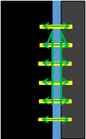
Tension in dowel bars created by hydrostatic head, dowel bars strain (extend).
An 8m depth of water implies 80kPa or 80kN if the dowel bar resists one metre square (for simplicity). E=(F/A)/(ext/original length). Ext/orig=(80/pi d2/4)/E, E (210GPa), d =40mm, implies 0.2mm/600mm multiplied by E (210GPa) equals 70MPa axial stress.
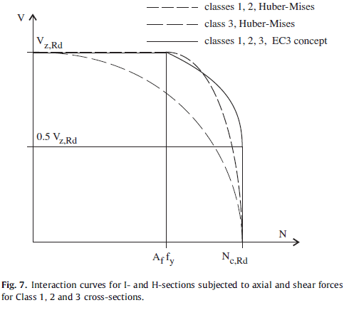
Remembering back to EC3 days or Von Mises, as axial force increases, shear decreases. Therefore this increase in stress in axial force (N) may reduce shear (V) to below the design capacity – Vz Rd reduces as axial force increases.
The question is why does the reinforcement bar extend by 0.2mm? The design specified a plain bar, the contractor installed a normal ribbed reinforcement bar into the secant wall which would generate tension between the secant wall and inner box as the hydrostatic head builds. A smooth bar would also lateral movement without reduction in shear capacity.
The problem is worsened when uplift occurs because the rebar it put into bending and therefore undergoes further reduction in capacity. See the 3D graph below where moment reduces capacity even more.

The solution (2)
Install a sleeve over the rebar thus removing the interlock effect of the ribs on the inner wall. This allows lateral movement of the dowel bars to avoid any axial force. Uplift is ten resisted by the dowel bars as planned in the design!
Summary
Clearly there are a number of assumptions and simplifications in this blog (basement box would also resist some lateral force reducing movement, soil type ignored, move to drained approach). I thought this issue was seemingly minor, but with an accumulation of risks (tri-axial forces) the consequences could be high. I would argue the likelihood of the risk arising is low but having specified a design solution to a complex problem, Arup was not going to reverse its view (with full finite element analysis to back up assertions) just to hurry the job along.
