Archive
Design Process
Design process
Background
The method of getting sewerage from the current outfall point in the Thames into the new Thames Tideway sewer is via a series of chambers and a 30m shaft. At the Putney site these chambers are located on a foreshore site. To facilitate the construction a cofferdam is required.
This blog looks at the approach taken to decide how to size up some piles for design development.

Putney Embankment Foreshore – End state river wall is the rectangular box in the foreground.
Durability
Tideway (the client) require a 120 year design life for all structures. This is onerous but after Guz’s recent blog on his river travels I can see why there is pressure to prove everything meets the design life.
Tender stage
Tender documents had the permanent cofferdam as a secant wall. To enable construction an outer vast temporary sheet piled cofferdam was proposed.
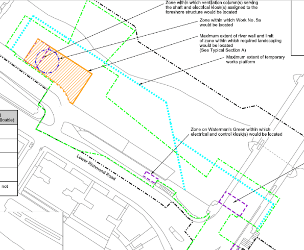
The blue dotted line is the extent of the tender document sheet pile wall. The orange box is the proposed site location.
The contractor’s tender submission was an optimised design by combining cofferdams to have a single thicker sheet piled solution which would satisfy temporary and permanent conditions.
Contractor’s tender submission – Sheet pile wall to act as a temporary and permanent wall.
The issue
Proving a sheet pile will last for 120 years is a bit tricky. The River Thames is fresh (ish) water but the fact sewerage is being discharged nearby creates a risk of microbial induced corrosion which erodes steel and makes arguing the case that all will be fine (as in only 1 or 2mm rather than 5 or 6mm difficult). Unfortunately the UK national annex is more onerous than the main eurocode, I.e. assumes more corrosion occurs.
Plan B
The contractor is keen to use a cofferdam which works in both temporary and permanent cases so have asked the Arup-Atkins joint venture to look at tubular piled options. Steel with concrete encased inside. This can be split into 2 cases. 1. Steel is non-sacrificial and last 120 years and 2. It does not.
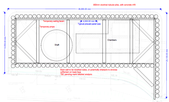
Tubular pile option – outline sketch only
How does the cofferdam get built?
- Modelling the construction sequence for either case is the same:
- Install cofferdam
- Install top prop
- Dewater
- Excavate to formation level
- Install base slab (acts as a bottom prop)
- Wait 2 years while shaft is excavated
- Move to drained conditions.
- Re-fill cofferdam/construct internal chambers to underside of prop level, back to undrained conditions.
- Remove temporary top prop.
- Finish cofferdam/structures, apply surcharge
- Excavate and place scour protection.
- Allow for some worst case tidal and tidal lag.
- Long term case – move to drained conditions.
- Case 1 – steel remains, Case 2 steel does not.
600mm tube option shown below.
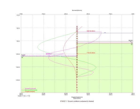
Stage 5-8 in stages above – excavation to full depth with base slab at drained conditions

Final stage with deflection of wall shown in red (105mm) and bending moment in green (1MN)
Stiffness
Understanding shear, bending and deflection throughout the sequence was key. Various pile diameters were tried but this was simply an adjustment of stiffness in the Frew model. EI based on section size, steel and concrete Young’s Modulus. 0.7EI and 0.5EI were used for temporary and permanent concrete strengths. The difference for the 120 year case comes at the final stage where only the section properties of a concrete section above bed level can be taken into account, i.e. a reduction is stiffness. More onerous is the reduction in moment capacity the section has without a steel pile included.
The results
After trying various tubular pile sizes I got to a 600mm pile for both cases above as worst moments were in temporary case (max excavation rather than maximum fill height), so loss of steel section was not an issue as final stage was still below moment capacity.
Unfortunately I made a stupid error in the fill material (somehow I assigned a granular fill a high cohesion value) within the cofferdam which meant I had lower bending moments in the long term than I should have. That was identified before presenting to the contractor so I only lost face internally.
The amended results showed that a 600mm diameter pile works in the non-sacrificial case and a 900mm diameter pile works in the sacrificial case (due to reduced moment capacity).
End state deflections were somewhat high (100mm) but all of the modelling was done at DA1 combination 2 which is not the case at SLS. Also some of the water profiling is a little unrealistic (high level inside the cofferdam, very low tide outside). There is, however, some assumed stress lockins. For example early stages see the wall bend inwards, later stages see it pushed outwards. Difficult to know if this will actually occur so this is a probable case and greater deflections might be expected.
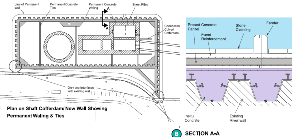
Cladding
The front face of the river wall has stone faced cladding panels which need to be fixed to the piled wall. The connection detail raises questions on durability – casting in stainless steel brackets works but if you touch a stainless steel bracket against a mild steel pile you get greater corrosion so some thought is needed to avoid that. Additionally, final deflections up to 100mm although equate to a small angle mean the top of the cladding is off-set further in order to backfill between the cladding panels and wall. This means the cladding load acts at a greater distance causing more deflection. It also makes it harder to pour something in between the piles and the cladding panels.
Design meeting
After a week of looking at all the options the proposed solution from Arup-Atkins (us) was the 600mm pile thick enough to corrode and be acceptable in the long term. I.e. a section size that was acceptable in the long term and then a corrosion allowance added. The contractor is now going to price this option. Although more expensive than a sheet pile option, it is cheaper than doing the vast sheet pile cofferdam and there are significant savings in temporary and permanent works (fewer internal props and ties needed because of the stiffer piles).
There was sensible input from the contractor about ease of installing 600mm diameter piles versus 900mm as well as lots of points about presenting a solution which meets the client’s durability concerns.
Outcome
We wait and see what Tideway say – they may reject all options and say build it as per the tender documents. If this is the case then I wonder what the point of early contractor involvement is.
Lessons
The whole issue and reason for having to look at alternative options is because of durability concerns raised by the client. The optimised contractor solution was/is a sensible plan and on a pain/gain contract it is worth trying to make savings.
The best thing I see having gone once around the process is developing multiple options to give the contractor the choice of what to present to the client. This enables a solution to be put forward on technical merit.
The plan to get the tubular pile costed before presenting to the client presents risk (for the contractor) has failed because of how busy the commercial team is right now which might turn out to be an issue.
I have learnt a lot about the importance of how something is to be done without the need to go into detailed calculations – certainly the case at concept design stage.
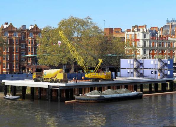
Temporary works jetty solution to build the new site. All by river approach demonstrated with barge removing spoil.
Oz NDY – Return Air Plenum Issues – Part 2
Following a site mtg we have a much clearer understanding of the issue at hand. The mech contractor, Envar, have sent us a mark-up (as requested) of the location and sizes of all holes made by the builder to initially increase air flow; which it has.
So why are we not getting the correct RA flow to the AHU? It also came to light that there is heavy congestion (as shown in fig 1) around a services (namely ducting) choke point (about 1 m2) which is restricting the RA flow. The congestion issue is unique to this level due to the balcony which a severely reduced the overall free area by approx. 1 m2. So, in theory we could turn the closest partition wall into a sieve and we would still have the problem. We can’t practically do this though as there isn’t enough space in this particular partition.
Therefore, we still need to get the balance of air from somewhere which the AHU fan is drawing in. So with the choke point in mind this will have to come from the SA side (the corridor) outside the plantroom. This corridor is open to the large open-plan office area but air flow either end is stopped by pneumatic actuated doors (for security as these areas are sub-tenanted). So what? The makeup air would be mostly SA and not RA as intended. So how does this affect the CO2 levels?
Below I’ve recalculated the area of hole required which would be incorporate as either a door grille in the plantroom door, or, depending on size, it could turn out to be a complete louvered door.
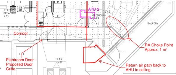
Figure 1. Return Air Choke Point in Plenum.
Calculations
A quick calculation to check the hole size required:
Q = 8.839 m3/s. This is the entire SA flow rate that is trying to get back to the AHU as RA.
A = 1 m2. The approx. area of free flow through the choke point.
Therefore, V = 8.8 m/s. That’s pretty quick and why it has also been reported that a few ceiling titles are flapping around near the exit hole from plenum into plantroom. These are being addressed by replacing with egg crate extract grilles.
If we want to achieve a steady flow rate of 5 m/s then this gives an A = 1.77 m2. Subtract from that the area we do have (1 m2) = 0.77 m2 hole required.
On a basic 2100 x 920mm door (leaving an edge of 100mm both sides) gives a door grille neck dimension requirement of 1100 x 720mm = 0.79 m2. That’s the ‘free air’ area needed where a louver or grille would require being 50 – 60% bigger to take into account the area lost due to the vanes. So, it would need to be 1.26m2, which is about 1800 x 720 = 1.29 m2 which equates to pretty much the entire door when you take into account the structural edges.
So what? It would require attenuation on the plant side of the door to mitigate plant noises transferring back into the corridor, which shouldn’t be heard too much anyway as it is just a corridor and the open-plan office area is actually through a central kitchen/restroom area.
To check this I spoke to our acoustic engineer and used the dB data. The corridor was reading 52 dB, I then added 25 dB for removal of the current door and then subtracted 5 dB for adding a louvered door with some attenuation on the reverse side. This results in 72 dB being heard in the corridor, which is about 22 dB over what it should be (50 dB being the norm). Therefore, this is a problem and exacerbated by the frequency range of the particular plant, which will be a low rumbling (low freq) which louvers still let through.
It would therefore be better to install an ATD above the plantroom door but this idea was discarded due to a large duct run right next to it running down the length of the corridor. This also means that we can’t put any more egg crate extract grilles in as the one currently installed sits no more than 10mm below the ductwork so this too will be restricting the RA.
The only other option I can see is putting in a large or two smaller ATDs through the wall area into the plantroom. But even this has its issues: is there free space on the other side of the wall? How far away is the AHU and can we fit a ATD in? Being the base build, will the building owner approve it?
I have also been informed the AHU has an economy cycle (which I should have expected) where the ambient OA temp dictates how much OA is used rather than wasting energy in cooling RA when there’s ‘free’ cool air available from outside.
ATDs
I made a point of mentioning the need for ATDs in the cut-outs. With the extra holes present no occupants have complained of cross-talk, therefore Envar suggested they would get the builder to tidy-up the holes and leave them at that. Ironically, it seems like any holes made in the partition wall don’t need attenuating due to the ductwork congestion.
