Design Process
Design process
Background
The method of getting sewerage from the current outfall point in the Thames into the new Thames Tideway sewer is via a series of chambers and a 30m shaft. At the Putney site these chambers are located on a foreshore site. To facilitate the construction a cofferdam is required.
This blog looks at the approach taken to decide how to size up some piles for design development.

Putney Embankment Foreshore – End state river wall is the rectangular box in the foreground.
Durability
Tideway (the client) require a 120 year design life for all structures. This is onerous but after Guz’s recent blog on his river travels I can see why there is pressure to prove everything meets the design life.
Tender stage
Tender documents had the permanent cofferdam as a secant wall. To enable construction an outer vast temporary sheet piled cofferdam was proposed.
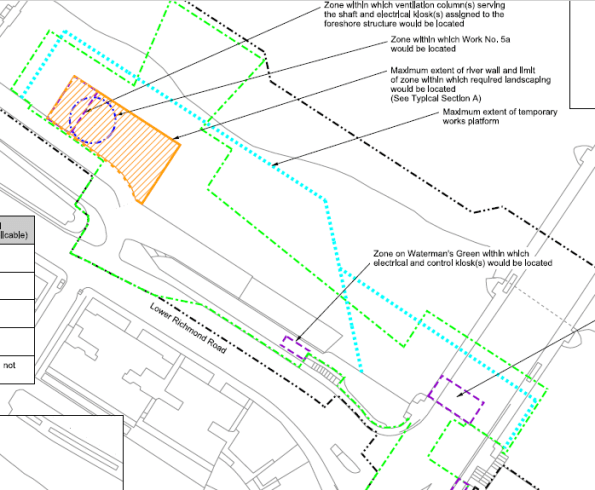
The blue dotted line is the extent of the tender document sheet pile wall. The orange box is the proposed site location.
The contractor’s tender submission was an optimised design by combining cofferdams to have a single thicker sheet piled solution which would satisfy temporary and permanent conditions.
Contractor’s tender submission – Sheet pile wall to act as a temporary and permanent wall.
The issue
Proving a sheet pile will last for 120 years is a bit tricky. The River Thames is fresh (ish) water but the fact sewerage is being discharged nearby creates a risk of microbial induced corrosion which erodes steel and makes arguing the case that all will be fine (as in only 1 or 2mm rather than 5 or 6mm difficult). Unfortunately the UK national annex is more onerous than the main eurocode, I.e. assumes more corrosion occurs.
Plan B
The contractor is keen to use a cofferdam which works in both temporary and permanent cases so have asked the Arup-Atkins joint venture to look at tubular piled options. Steel with concrete encased inside. This can be split into 2 cases. 1. Steel is non-sacrificial and last 120 years and 2. It does not.
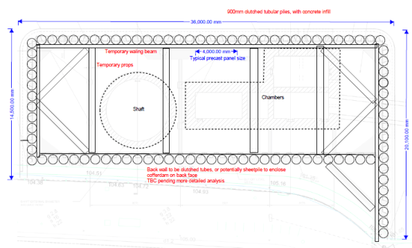
Tubular pile option – outline sketch only
How does the cofferdam get built?
- Modelling the construction sequence for either case is the same:
- Install cofferdam
- Install top prop
- Dewater
- Excavate to formation level
- Install base slab (acts as a bottom prop)
- Wait 2 years while shaft is excavated
- Move to drained conditions.
- Re-fill cofferdam/construct internal chambers to underside of prop level, back to undrained conditions.
- Remove temporary top prop.
- Finish cofferdam/structures, apply surcharge
- Excavate and place scour protection.
- Allow for some worst case tidal and tidal lag.
- Long term case – move to drained conditions.
- Case 1 – steel remains, Case 2 steel does not.
600mm tube option shown below.
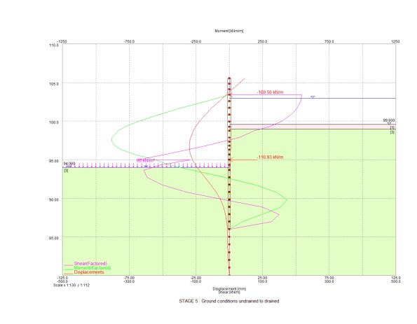
Stage 5-8 in stages above – excavation to full depth with base slab at drained conditions

Final stage with deflection of wall shown in red (105mm) and bending moment in green (1MN)
Stiffness
Understanding shear, bending and deflection throughout the sequence was key. Various pile diameters were tried but this was simply an adjustment of stiffness in the Frew model. EI based on section size, steel and concrete Young’s Modulus. 0.7EI and 0.5EI were used for temporary and permanent concrete strengths. The difference for the 120 year case comes at the final stage where only the section properties of a concrete section above bed level can be taken into account, i.e. a reduction is stiffness. More onerous is the reduction in moment capacity the section has without a steel pile included.
The results
After trying various tubular pile sizes I got to a 600mm pile for both cases above as worst moments were in temporary case (max excavation rather than maximum fill height), so loss of steel section was not an issue as final stage was still below moment capacity.
Unfortunately I made a stupid error in the fill material (somehow I assigned a granular fill a high cohesion value) within the cofferdam which meant I had lower bending moments in the long term than I should have. That was identified before presenting to the contractor so I only lost face internally.
The amended results showed that a 600mm diameter pile works in the non-sacrificial case and a 900mm diameter pile works in the sacrificial case (due to reduced moment capacity).
End state deflections were somewhat high (100mm) but all of the modelling was done at DA1 combination 2 which is not the case at SLS. Also some of the water profiling is a little unrealistic (high level inside the cofferdam, very low tide outside). There is, however, some assumed stress lockins. For example early stages see the wall bend inwards, later stages see it pushed outwards. Difficult to know if this will actually occur so this is a probable case and greater deflections might be expected.
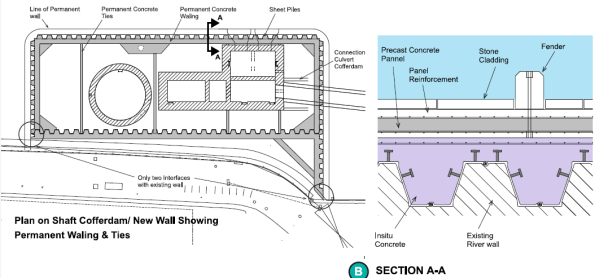
Cladding
The front face of the river wall has stone faced cladding panels which need to be fixed to the piled wall. The connection detail raises questions on durability – casting in stainless steel brackets works but if you touch a stainless steel bracket against a mild steel pile you get greater corrosion so some thought is needed to avoid that. Additionally, final deflections up to 100mm although equate to a small angle mean the top of the cladding is off-set further in order to backfill between the cladding panels and wall. This means the cladding load acts at a greater distance causing more deflection. It also makes it harder to pour something in between the piles and the cladding panels.
Design meeting
After a week of looking at all the options the proposed solution from Arup-Atkins (us) was the 600mm pile thick enough to corrode and be acceptable in the long term. I.e. a section size that was acceptable in the long term and then a corrosion allowance added. The contractor is now going to price this option. Although more expensive than a sheet pile option, it is cheaper than doing the vast sheet pile cofferdam and there are significant savings in temporary and permanent works (fewer internal props and ties needed because of the stiffer piles).
There was sensible input from the contractor about ease of installing 600mm diameter piles versus 900mm as well as lots of points about presenting a solution which meets the client’s durability concerns.
Outcome
We wait and see what Tideway say – they may reject all options and say build it as per the tender documents. If this is the case then I wonder what the point of early contractor involvement is.
Lessons
The whole issue and reason for having to look at alternative options is because of durability concerns raised by the client. The optimised contractor solution was/is a sensible plan and on a pain/gain contract it is worth trying to make savings.
The best thing I see having gone once around the process is developing multiple options to give the contractor the choice of what to present to the client. This enables a solution to be put forward on technical merit.
The plan to get the tubular pile costed before presenting to the client presents risk (for the contractor) has failed because of how busy the commercial team is right now which might turn out to be an issue.
I have learnt a lot about the importance of how something is to be done without the need to go into detailed calculations – certainly the case at concept design stage.
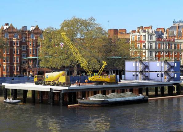
Temporary works jetty solution to build the new site. All by river approach demonstrated with barge removing spoil.

I assume you won’t be privvy to the numbers in terms of the cost savings. In my experience as a client, although not on decisions as big, is that if they get the performance they ask for and get a credit they’ll be broadly happy. The issue tends to be when the performance is slightly compromised by something that you think is innocuous but, rightly or wrongly, they don’t.
Hi Henry, yes if cost and quality are acceptable then a client is normally happy. In this case the quality is in question and on a design and build target cost contract the client is in their right to ensure quality is met. The difficulty when working at the extreme end of the scale is proving compliance. The client has CH2M (sp?) as their representative engineer so everything, rightly, is thoroughly scrutinised.
If you believe you are operating at the edge of the acceptable has anything extra been done in terms of presentation of the information to ensure it is approved?
Hi Henry, ‘by extreme end of the scale’, I mean design life, rather than us trying to skimp on meeting the standards. Typically civil infrastructure requires a significantly longer design life than for buildings. Therefore codes and standards which list scales for durability tend to be at the top end limits when nearing 120 years. That is, therefore, not to say our design is on the edge of being acceptable but more what is acceptable for a 120-design life. Predictions and simulations of how materials perform over that amount of time rely on current assumptions, but over that period clearly much can change. There is a balance between over engineering and sensibly meeting the requirements. Moreover, as Guz highlighted, much of how something performs in how well it was constructed. A wall compacted concrete of a lower grade may outperform a higher grade concrete with lots of voids in and water paths to reinforcement are present.
The presentation of the information is being done firstly with a durability assessment of all things corrosion at the site. This will inform the client what the situation is and how the design is compliant. The issue almost seems to be an optimised solution by the contractor is doubted because it goes against the client’s tender drawings. If this is the real reason for the reluctance in accepting change, then I say again, what is the point in having early contractor involvement.
Damo, there is probably a really easy answer to this that I am missing, but why (in step 9) do you move back to undrained conditions?
I understand you are loading vertically, but why is it assumed that changes the effective stress felt the far side of the retaining wall?
Hi Guz, thanks for the question. I think a question of whether drained conditions are reached during the shaft excavation is an equally good discussion. My take (on your question) is that for drained conditions there needs to be pore water pressure equilibrium everywhere within the bounds of the problem. By increasing the total vertical stress inside the cofferdam that creates excess pore pressure and therefore a hydraulic gradient. It needs to dissipate/equalise somehow and so there is a drainage path. In my view this extends beneath the wall to the river side. Therefore the far side cannot remain drained. You could argue that far away it is not affected by the works but how far is far.
Another issue I have mental problems with is a differential water level inside and outside the cofferdam at the final stage. For drained conditions to be valid there cannot be a difference in head, yet clearly in the long term the works will have finished and the ground will have equalised pore pressures. If the tide then comes in, does it really turn to undrained?
Final point is that the most likely situation is partial drainage but trying to work that out is a non-starter.
You have “mental problems”? Finally some recognition, it is the first step to seeking help!
Given the material, I don’t think the tidal patterns will affect the pore pressure, the tide isn’t in long enough to substantially affect the pore pressure through hydraulic gradient. It’s a good point though, where do you take the mean river level at?
Hi Guz, yes had to say it! I have gone for mean high water springs (about 104m ATD) for worst outside during construction. Then same inside when structures inside are complete and Chart Datum (about 98m ATD) outside. I think these are a bit onerous so on the conservative side of things.
For long term drained conditions I have left the inside and outside levels equal.
Hi Damian,
Sory to join the party so late on. Other than the dwhen is drained drained conundrum I note the intention to use a steel tubeular pile with concrete fill. Has consideration been given to using internal cages to increase the moment cpoapcity over critical secions in order to reduce the deflections? CLearly the actual desing is into the weeds but conceptually it should help with your cladding and fixings. does the cladding become a composti element over these sections anyway?
Hi Richard, thanks for the comments. Cages have been considered practically for max bending section, but stiffness of wall has been considered from concrete and steel tube contribution only (not cage). I think having established a tubular section size at this stage, deflection reduction will come a little later dependent on the option chosen. The wider issue of gaining acceptance for the contractor’s preferred sheet piled solution is under Client review now after Arup Atkins’s submission of the durability assessment report – a light 15k report. Cladding just hangs off the piles with a non-structural infill in the gap, it does not add benefit serviceability wise, especially as it is a subsequent activity after the new structure is mostly completed.
Richard, I need to come back to you on your adding reinforcement question. I think considering reinforcement is a bit of a red herring. Adding more reinforcement into a pile will increase stiffness – which attracts more load and therefore deflection. Using reinforcement to reduce deflections might not be an economical method. I think an efficient scheme would consider temporary/permanent props, their spacing, location and sizes. For example the addition of a permanent base slab may enable removal of top props so the retained wall acts as a cantilever. This in turn might reduce duration of the propping scheme and also make construction inside the excavation simpler and less dangerous.